Linkage Animations (original) (raw)
Animations of linkage movement.
Wing Mechanisms
June 7, 2021/
Repurposing Jansen’s Leg Mechanism:
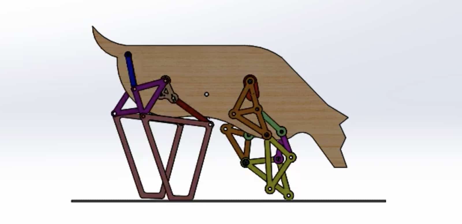
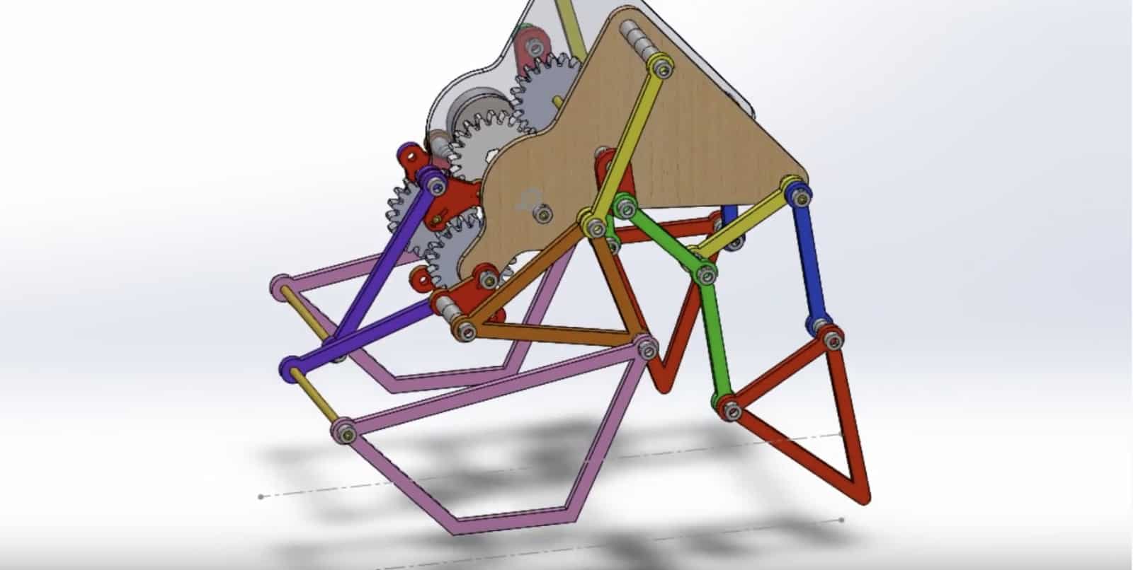
Innovative mechanical flyers were designed by student teams in my Kinematic Synthesis class based on a repurposed version of Jansen’s leg mechanism. The artist Theo Jansen has inspired many of my students with his dramatic assemblies of leg mechanisms to form his Strandbeest wandering on a beach under the power of a sea breeze.
A generalization of Jansen’s leg has the hip and knee joints driven by separate four-bar function generators to provide a wide variety of foot trajectories. This generalized version of Jansen’s linkage can be adapted to form a wing mechanism that has a desired wing-tip trajectory.
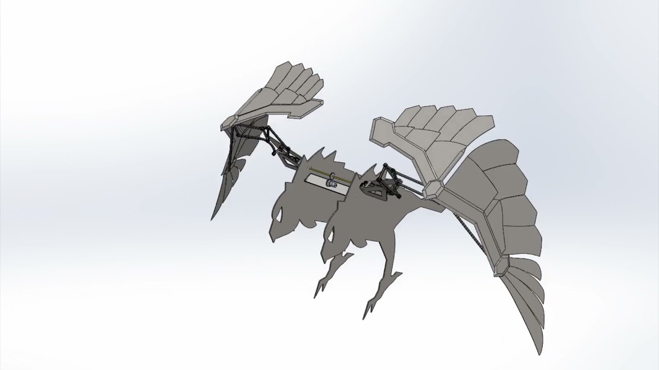
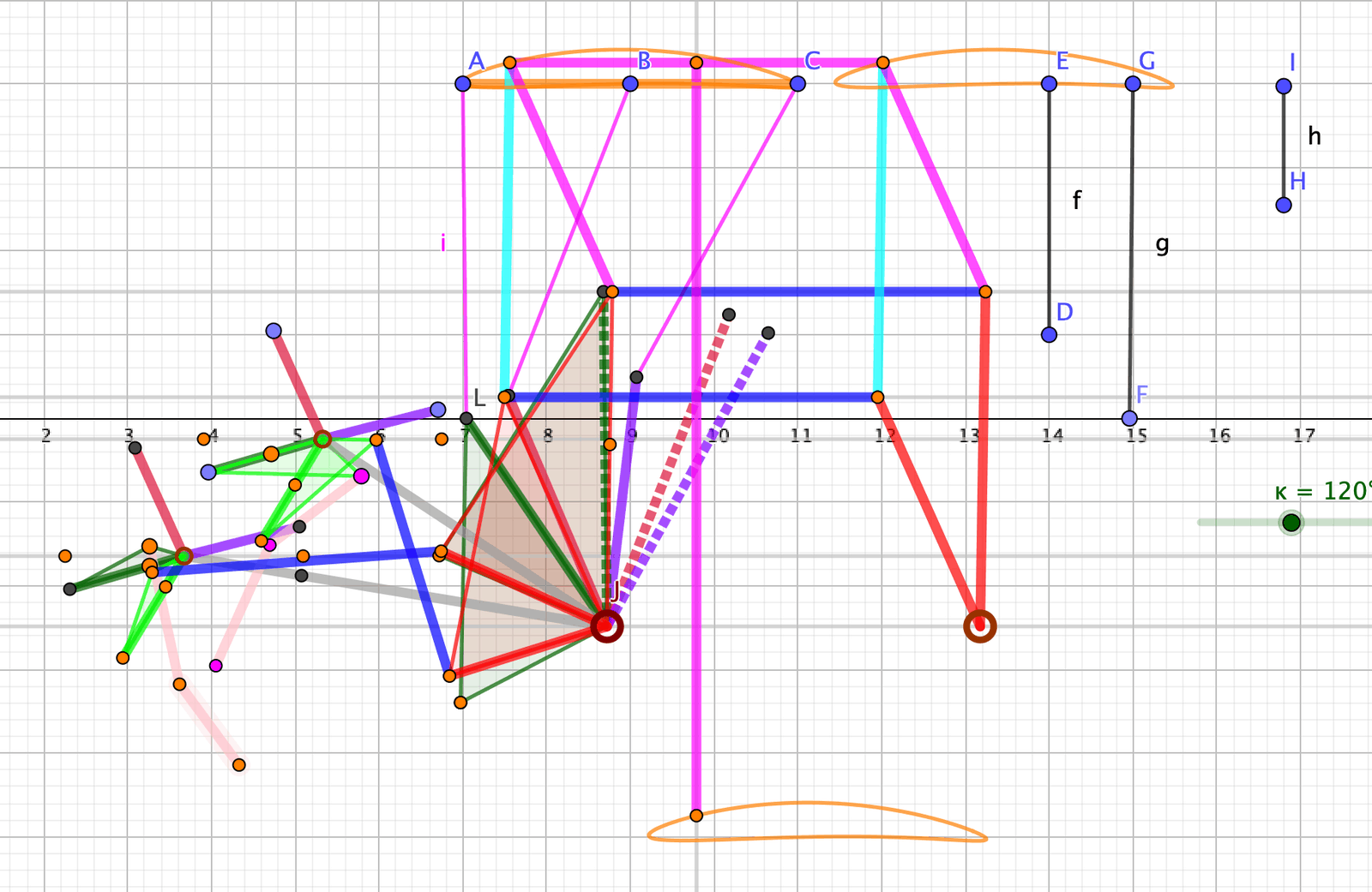
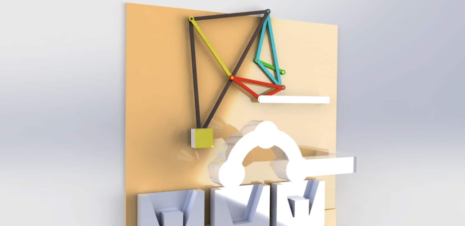
This video shows the Geogebra model of a wing mechanism based on Jansen’s linkage, and three digital prototypes of mechanical flyers obtained by my students using this mechanism.
https://mechanicaldesign101.com/wp-content/uploads/2021/06/maxresdefault-1.jpg 720 1280 Prof. McCarthy https://mechanicaldesign101.com/wp-content/uploads/2016/07/mechanical-design-101LOGOf.png Prof. McCarthy2021-06-07 13:19:352022-09-17 09:25:54Wing Mechanisms
How to Fix SW Motion Analysis Error: Too Many Redundant Constraints
July 19, 2020/by Prof. McCarthy
Kevin Chen, J. Michael McCarthy, Shaun Bentley
The design and assembly of our four-legged mechanical walkers can yield single degree-of-freedom systems with so many redundant mates that it stalls SolidWorks’ Motion Analysis. For example, the walker shown in Figure 1 had 782 redundant mates. The procedure outlined below reduced the number of redundant mates to 114, and Motion Analysis executed efficiently.
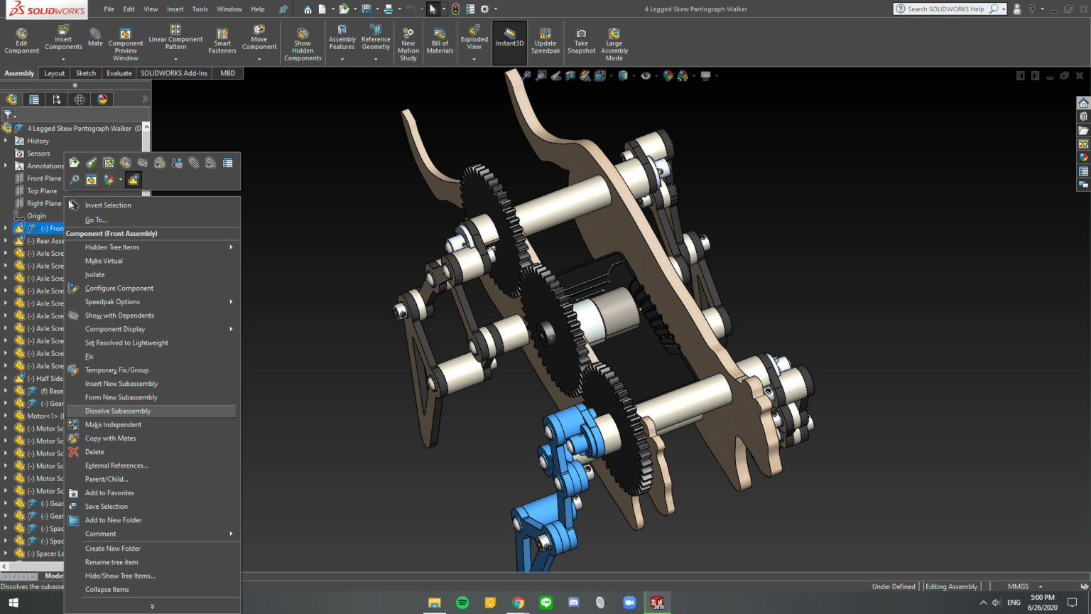
Figure 1. A four-legged mechanical walker consisting of a body, drive train, and four-leg mechanisms.
Our walker consists of a body, drive train, and four legs. The legs mechanisms are identical but assembled as front-to-back mirror images. The component parts of this walker mates were assembled using mates to align and coordinate various subassemblies, resulting in a large number of redundant mates.
In order to reduce the number of redundant mates, we dissolve the subassemblies, combine rigid elements, and mate new subassemblies as follows.
Step 1
Dissolve all of the subassemblies in the walker. To do this, hover over each assembly and select the menu item Dissolve Assembly. See Figure 1.
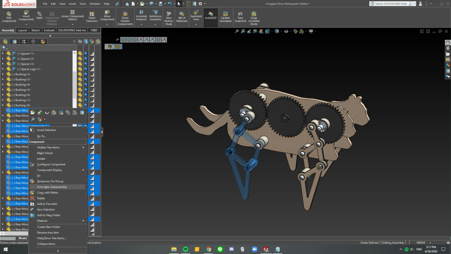
Figure 2. Selected parts for new subassembly.
Step 2
Form new subassemblies for each leg, the drive train, and the body. See Figure 2. To do this, first, hover over the part, press “tab” to hide the part in order to identify it easily; and then, select all of the hidden parts, and right-click to open menu and select Form New Subassembly.
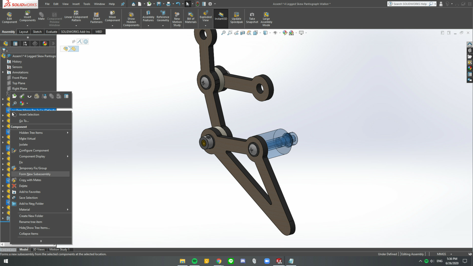
Figure 3. Within each new subassembly form subassemblies of parts that do not move relative to each other.
Step 3
Within each new subassembly combine parts that do not move relative to each other. See Figure 3. The tree structure should consist of separate assemblies of rigid elements with the remaining mates between the assemblies. See Figure 4.
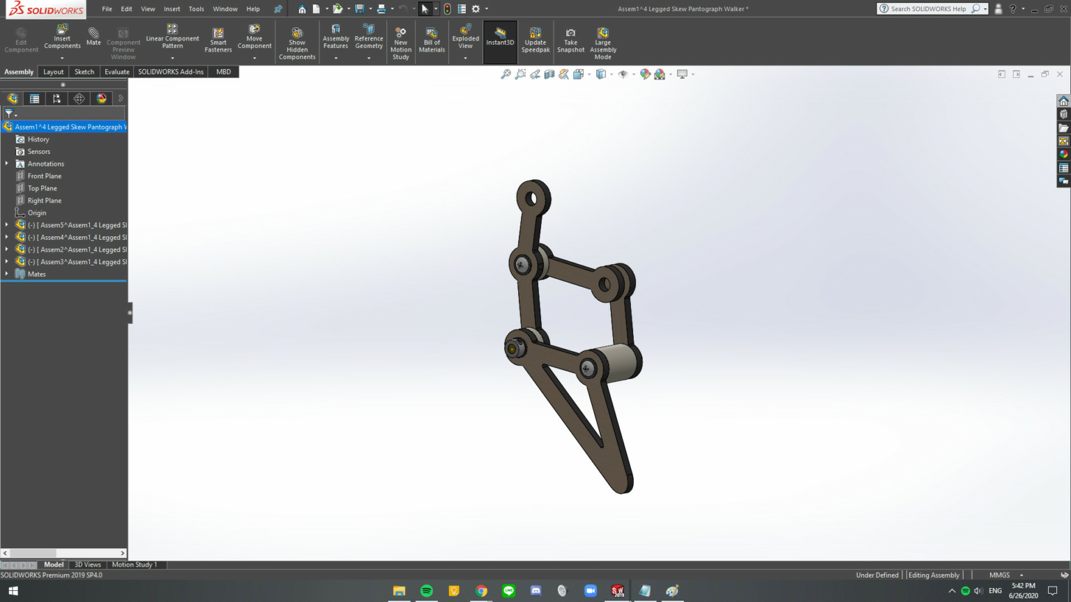
Figure 4. The assembly should consist of subassemblies that move as rigid elements relative to each other.
Step 4
Repeat Step 3 for all of the new subassemblies. The result is shown in Figure 5.
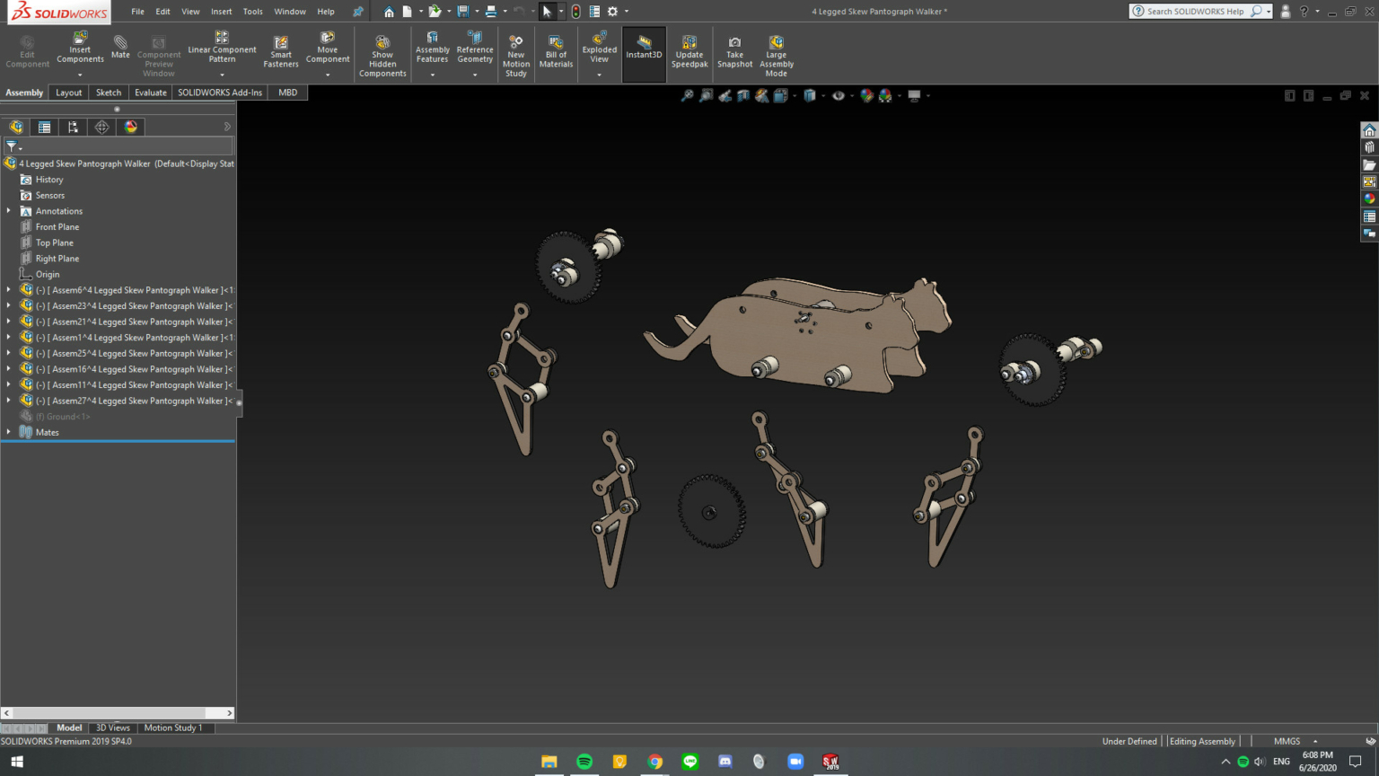
Figure 5. The subassemblies that define the mechanical walker. Notice that the tree structure consists of subassemblies and no individual parts.
Step 5
Delete the mates in the main assembly. Introduce the mates required for movement using hinge mates, rather than coincident or concentric mates, where possible.
Step 6
Make the subassemblies at the top-level flexible. Right-click on the assembly and select the flexible assembly icon .
The result of this procedure is a system with 114 redundant mates that Motion Analysis can process effectively. The result is that animation shown below.
https://mechanicaldesign101.com/wp-content/uploads/2020/07/Screen-Shot-2020-07-19-at-5.12.37-PM.png 799 1600 Prof. McCarthy https://mechanicaldesign101.com/wp-content/uploads/2016/07/mechanical-design-101LOGOf.png Prof. McCarthy2020-07-19 17:15:522020-07-19 17:39:58How to Fix SW Motion Analysis Error: Too Many Redundant Constraints
Six-Legged Mechanical Walkers: Spring 2020 Highlights
June 19, 2020/by Prof. McCarthy
The leg mechanisms of these six-legged walkers use two coordinated function generators to drive the hip and knee joints to achieve the desired foot trajectory. This differs from Jansen’s leg mechanism in the following ways: (i) separate cranks can be used to drive the hip and knee joints, rather than the same crank driving both joints; (ii) the drive of the hip joint need not be connected at the knee but can connect any where on the upper leg; and (iii) a true parallelogram is used to connect the drive around the hip down to the knee, whereas Jansen’s connection has one side slightly larger for both pairs (39.3, and 39.4 for one pair of sides, and 40.1 and 36.7 for the other pair). So these leg mechanisms can be viewed as generalizations of Jansen’s design.
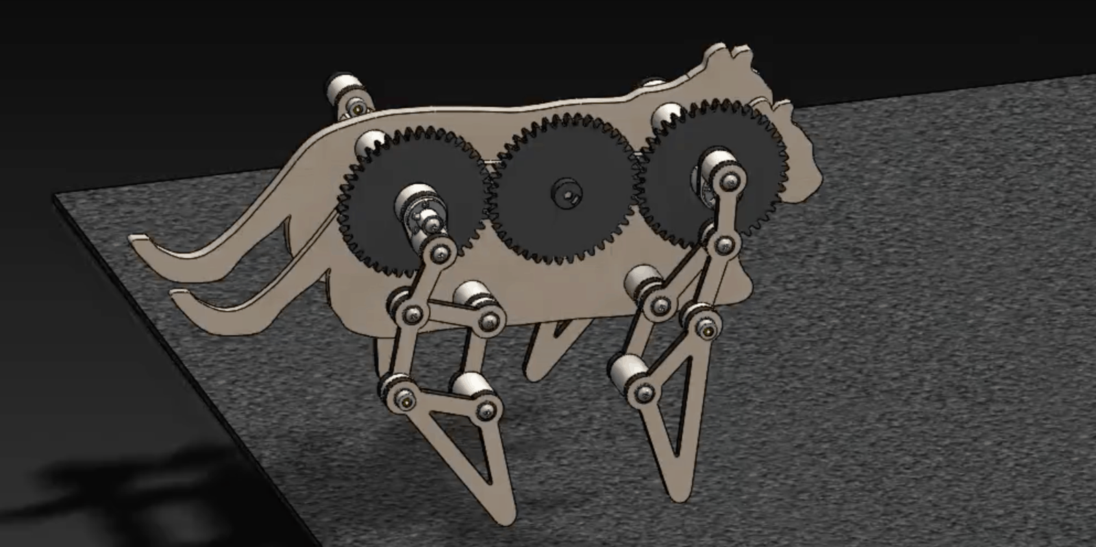
Stable gait for these walkers can be achieved by coordinating three legs at a time to form a tripod gait. Please see this video showing walkers designed by my students to be a crocodile, rhinoceros, bug, legged container and the Star Wars All-Terrain Tactical Enforcer, known as AT-TE. These assemblies of six 10-bar linkages connected by a gear train of as many as 18 gears posed a challenge to SolidWorks motion analysis for my students. We will get better at this.
https://mechanicaldesign101.com/wp-content/uploads/2020/06/maxresdefault.jpg 720 1280 Prof. McCarthy https://mechanicaldesign101.com/wp-content/uploads/2016/07/mechanical-design-101LOGOf.png Prof. McCarthy2020-06-19 16:58:302022-09-17 09:25:54Six-Legged Mechanical Walkers: Spring 2020 Highlights
Four-Legged Mechanical Walkers: Spring 2020 Highlights
June 17, 2020/by Prof. McCarthy
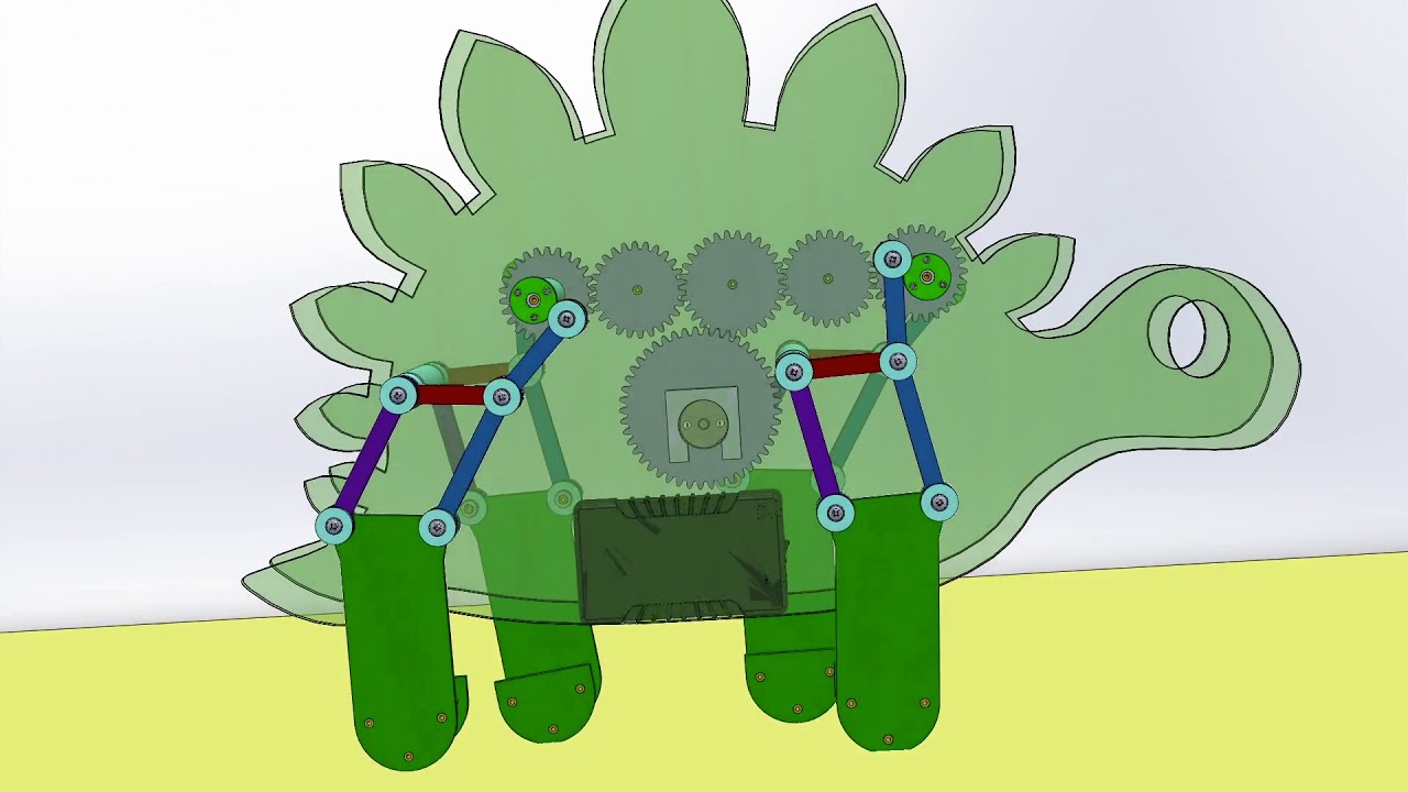
The design of these four-legged walkers relies on Curvature theory to find a flat-sided coupler curve of a four-bar linkage to be used for the foot trajectory. This coupler curve is repositioned using a skew pantograph. The result is a six-bar leg mechanism.
Stable gait for these walkers can be achieved by adding side-to-side foot extensions to broaden the support polygon during walking.
Please see this video showing walkers designed by my students to be a rabbit, two dogs, a bear, a rhinoceros, a dinosaur, and a centaur, as well as a legged platform, a legged syringe and the Star Wars All-Terrain Attack Transport, known as AT-AT.
https://mechanicaldesign101.com/wp-content/uploads/2020/06/maxresdefault-2.jpg 720 1280 Prof. McCarthy https://mechanicaldesign101.com/wp-content/uploads/2016/07/mechanical-design-101LOGOf.png Prof. McCarthy2020-06-17 14:19:492022-09-17 09:25:54Four-Legged Mechanical Walkers: Spring 2020 Highlights
Four-legged Mechanical Walkers: Teams 2, 4 and 5
December 13, 2019/by Prof. McCarthy
Here are videos of the designs for the four legged mechanical walkers obtained by Teams 2, 4 an 5. This is the final project in my Fall 2019 Kinematic Synthesis course.
Team 2
Mechanical Walker Team 2
Team 4
Mechanical Walker Team 4
Team 5
Mechanical Walker Team 5
https://mechanicaldesign101.com/wp-content/uploads/2019/12/Screen-Shot-2019-12-13-at-1.48.24-PM.jpg 777 1600 Prof. McCarthy https://mechanicaldesign101.com/wp-content/uploads/2016/07/mechanical-design-101LOGOf.png Prof. McCarthy2019-12-13 13:51:112020-06-15 14:16:07Four-legged Mechanical Walkers: Teams 2, 4 and 5
Four Legged Mechanical Walker: Teams 1, 3 and 6
December 8, 2019/by Prof. McCarthy
Here are videos of the designs for the four legged mechanical walkers obtained by Teams 1, 3 an 6. This is the final project in my Fall 2019 Kinematic Synthesis course.
Team 1
Mechanical Walker designed by Team 1.
Team 3
Mechanical Walker designed by Team 3
Team 6
Mechanical Walker designed by Team 6.
https://mechanicaldesign101.com/wp-content/uploads/2019/12/Screen-Shot-2019-12-08-at-1.02.45-PM.jpg 806 1600 Prof. McCarthy https://mechanicaldesign101.com/wp-content/uploads/2016/07/mechanical-design-101LOGOf.png Prof. McCarthy2019-12-08 13:05:322019-12-08 13:07:54Four Legged Mechanical Walker: Teams 1, 3 and 6
Construction of a Leg Mechanism
May 23, 2019/by Prof. McCarthy
This is a series of four videos that show how to:
- Specify three positions for the foot of a leg consisting of a hip and knee joint;
- Use three position synthesis to design a four-bar function generator to guide the hip joint;
- Then use three position synthesis to design a second four-bar function generator to guide the knee joint;
- And finally assemble the linkage to determine the trajectory of the foot. Adjusting the lengths of the leg segments, the position of the hip, the specified positions of the input cranks, and the position of the coupler attachments to the input cranks vary the resulting foot trajectory. An example leg mechanism is shown at the end of this video.
Part 1:4 Setting up the design
Part 2:4 Synthesis of the hip function generator.
Part 3:4 Synthesis of the knee function generator.
Part 4:4 Assembly of the leg mechanism, exploration of design variations, and an example final leg design.
https://mechanicaldesign101.com/wp-content/uploads/2019/05/Screen-Shot-2019-05-23-at-4.16.12-PM.png 1041 1600 Prof. McCarthy https://mechanicaldesign101.com/wp-content/uploads/2016/07/mechanical-design-101LOGOf.png Prof. McCarthy2019-05-23 16:27:142019-05-25 12:37:37Construction of a Leg Mechanism
Rectilinear Six-Bar (Candy Coating Linkage)
January 14, 2018/by Prof. McCarthy
Jeff Glabe designed this six-bar linkage to move through six task positions while maintaining a parallel orientation. This required the calculation of 55,000 linkages to find 26 that work. This one has the additional feature that it is operated by a rotating crank (the red link). The video is a collaboration of Jeff Glabe and Benjamin Liu.
https://mechanicaldesign101.com/wp-content/uploads/2018/01/Screen-Shot-2018-01-14-at-2.43.53-PM.jpg 777 1600 Prof. McCarthy https://mechanicaldesign101.com/wp-content/uploads/2016/07/mechanical-design-101LOGOf.png Prof. McCarthy2018-01-14 14:43:132018-01-14 14:50:46Rectilinear Six-Bar (Candy Coating Linkage)
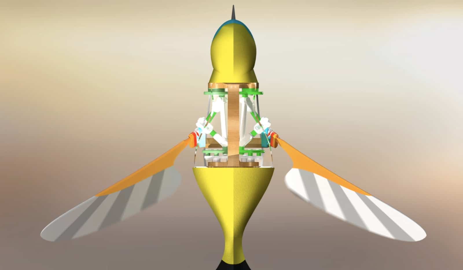
Hummingbird Spatial Six-bar Linkage
October 13, 2017/by Prof. McCarthy
This spatial six-bar linkage provides a compact flapping wing mechanism for a hovering micro air vehicle that controls both swing and pitch movements. It is the result of a collaboration between Benjamin Liu and Peter Wang.
https://mechanicaldesign101.com/wp-content/uploads/2017/10/Hummingbird-Six-bar.jpg 935 1600 Prof. McCarthy https://mechanicaldesign101.com/wp-content/uploads/2016/07/mechanical-design-101LOGOf.png Prof. McCarthy2017-10-13 11:00:482017-10-13 11:09:06Hummingbird Spatial Six-bar Linkage
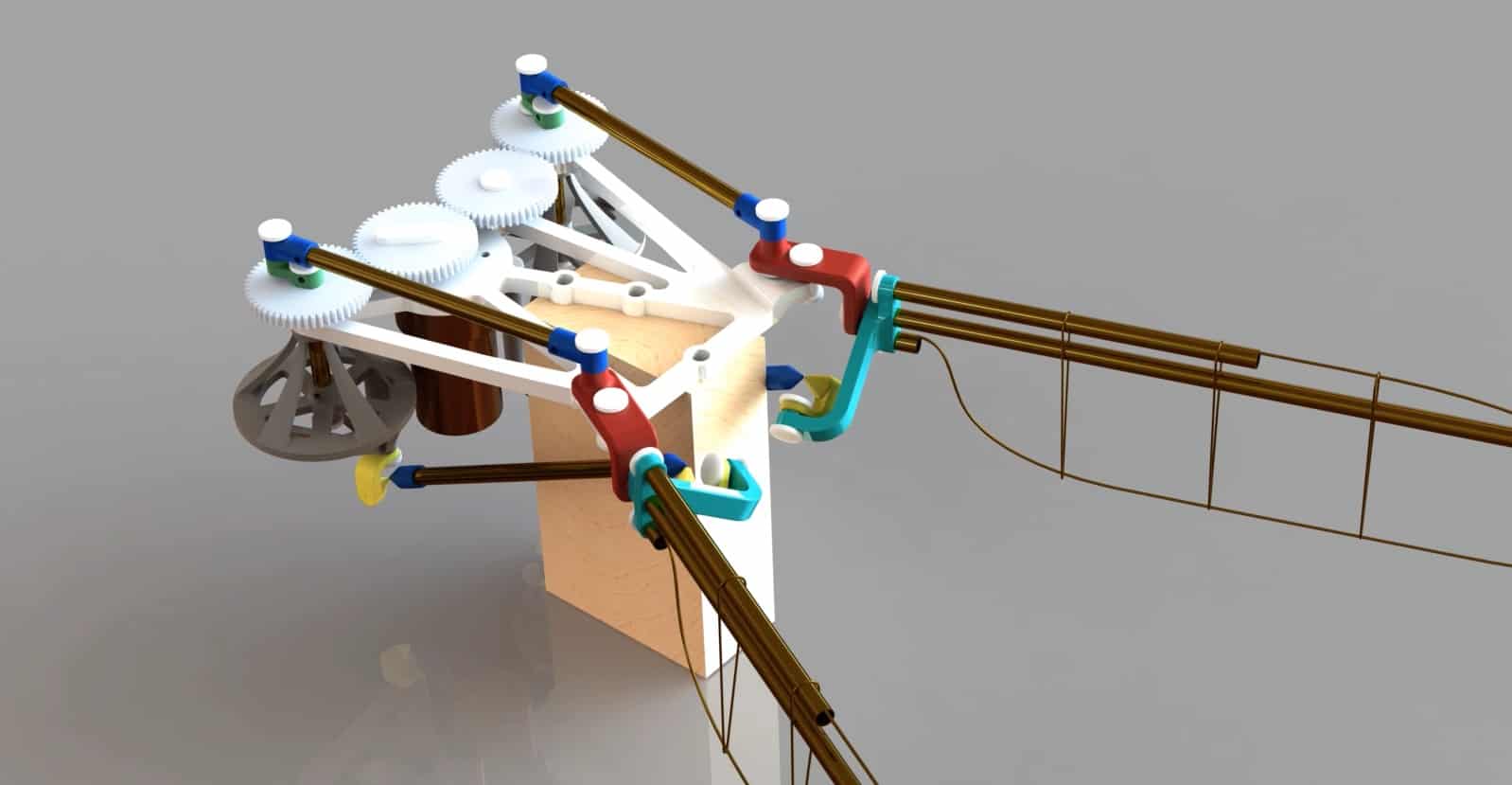
Flapping Wing Prototype
August 16, 2017/by Prof. McCarthy
This is the manufacturing prototype for the flapping wing mechanism designed by Peter Wang and modeled by Benjamin Liu. The wing is 5cm in length to match the dimensions of a hummingbird.
Here is a link to the youku.com video for our Chinese colleagues: Flapping Wing Prototype.
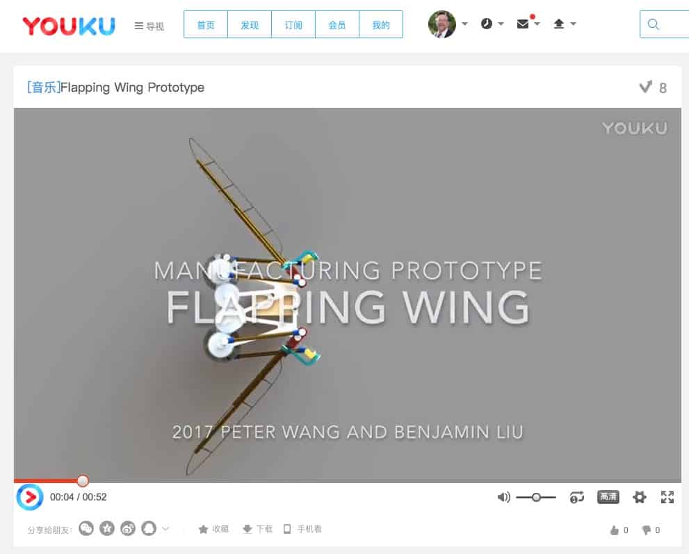
Youku Flapping Wing
https://mechanicaldesign101.com/wp-content/uploads/2017/08/Flapping-Wing-Prototype.jpg 829 1598 Prof. McCarthy https://mechanicaldesign101.com/wp-content/uploads/2016/07/mechanical-design-101LOGOf.png Prof. McCarthy2017-08-16 10:39:472017-08-18 21:31:59Flapping Wing Prototype