ADS1115 I2C external ADC with ESP32 in Arduino IDE (original) (raw)

This guide will assist you in interfacing the external ADC module AD1115 with ESP32. This is done to measure analog voltages with high accuracy. The ADS1115 external ADC module can send data over the I2C protocol. For learning more about I2C communication, you can check out our in-depth tutorial I2C Communication Protocol Basics. Now moving on to the module, it consists of four analog channels named as A0, A1, A2, and A3 respectively.
At the end of this guide, we will provide an example of analog voltage measurement with ADS1115 and ESP32. This will include explanation and a complete code schematic to help you understand this tutorial.
Why do we need to use an external ADC with ESP32?
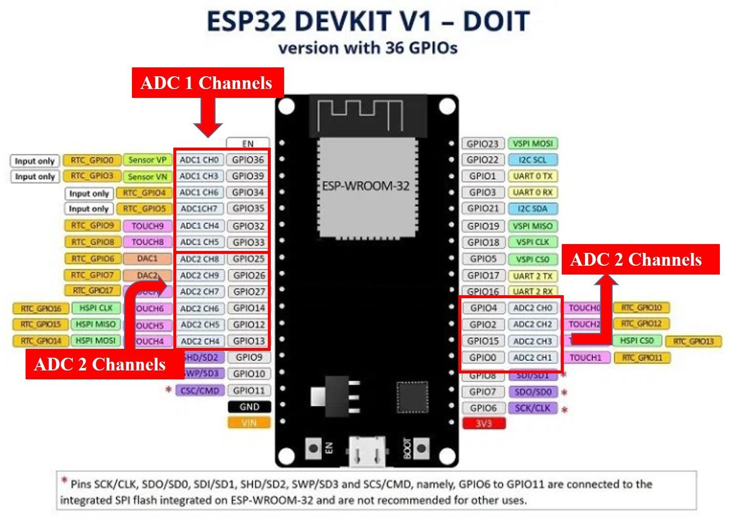
Although, ESP32 has two built-in ADC modules namely; ADC1 and ADC2. These two modules are of 12-bits each and further divided into 8 and 10 channels respectively.

To learn in-depth about ESP32 ADC channels and their working you can refer to our article ESP32 ADC tutorial. But, we will discuss some of the issues here.
- Channel limitation due to overlapping functionality of touch pins (in ADC2) and internal reference voltage measurements (in ADC1).
- Non-linear characteristics and behavior during voltage measurement via ADC channels.
- Very low resolution of ESP32 ADC, it is unable to differentiate between 1mV and 2mV signals. Which can be very challenging for people requiring accurate results.
In order to resolve these issues, we can use an external high resolution programmable ADC IC, such as ADC1115 external ADC module.
Reasons to use External ADC Converter
Their are two main reasons to use External ADC converter with ESP32
Low resolution and non linear behavior: ESP32 has low resolution and non-linear behavior in its ADC channels, this issue can be resolved easily by connecting an external ADC module with ESP32. This will enable ESP32 to measure analog signal with higher accuracy. Other than this ESP32 has all the excellent features expected from a development board for IOT projects.
Interfacing issues : For example, you want to interface LM35 temperature sensor with ESP32, you can not connect it directly due to low resolution and inaccurate behavior of built-in analog to digital converter of ESP32. LM35 temperature sensor gives the output of 1mV per one degree centigrade of temperature. Built-in ADC can not measure 1mV accurately and so ESP32 fails to provide accurate data. This issue can also be resolved by connecting External ADC converter.
Introduction to ADS1115 External ADC
ADS1115 is a 16-bit analog to digital converter that consists of four analog channels. It can be used to measure both positive and negative voltages. ADS1115 works in Single Ended Differential mode or comparator mode.
| Operating Mode | Output |
|---|---|
| Single Ended Differential | This mode can measure positive voltages only. So no negative output can be processed in this mode. |
| Comparator | The Comparator mode is capable of processing both the positiveas well as the negative voltages. It becomes very useful when battery voltages are measured. |
Table 1: Operating Mode of ADS1115 External ADC Module
We can interface it with any microcontroller having I2C communication support. It has four modes and It also has a programmable comparator which can make it more effective for projects.
Features of ADS1115
ADS1115 is a 16-bit I2C protocol based ADC having four analog channels. It provides output in signed integer format. From total 16-bits, one bit is assigned for positive and negative number. Therefore, only 15 bits are used to measure the voltage and ADC resolution is calculated according to these 15 bits.
- We get 2^15 = 32,768 possible output values for every analog input.
- The range of possible digital output is between 0 – 32767.
- These 15 bits are used to get the magnitude of voltage through I2C communication.
- The weight of every bit can be defined with the Programmable Gain Amplifier (PGA) by setting a reference voltage value.
- In the default mode, the reference voltage value is +/-6.144 volts.
- The digital output is represented as 0 for 0V and 32767 for 6.144V.
- But we can not measure 6.144 volts directly with this chip (ESP32). The maximum voltage which we can measure depends on the supply voltage to the chip, which is 5.5 volts in case of ADS1115.
Resolution of ADS1115
- We can calculate the resolution of ADS1115 External ADC by dividing maximum voltage (6.144V) with maximum digital output (32767), which becomes equal to 0.1875mV.
- So the minimum analog voltage we can measure with ADS1115 external I2C ADC is 0.1875mV which is almost 50% greater in accuracy than the built-in analog to digital converter module of ESP32.
Pinout of ADS1115

It consists of four pins and the table below shows functionality of each pin.
| Pin name | Functionality |
|---|---|
| Vdd ( Power supply pin) | Connect power supply between 2.2 – 5.5 volts |
| GND ( Common reference pin ) | Connect with ground pin of power supply |
| SCL | I2C SCL ( serial clock pin) |
| SDA | I2C SDA ( Serial data pin) |
| ADDR | I2C slave select pin or address |
| ALRT | Alert/Ready |
| A0 | Analog channel 0 |
| A1 | Analog channel 1 |
| A2 | Analog channel 2 |
| A3 | Analog channel 3 |
Table 2: ADS1115 ADC pins and functions
We can set 4 different addressing modes by connecting the address pin with SCL, SDA, GND or VDD. Table below provides description on connection of address pin with SCL, SDA, GND or VDD pin according to the address value.
| ADDR pin value | Connection with Pin |
|---|---|
| 0x48 | Connect address pin to GND |
| 0x49 | Connect address pin to VDD |
| 0x4A | Connect address pin to SDA |
| 0x4B | Connect address pin to SCL |
Table 3: ADS1115 pin address
ADDR pin is used for the selection of four different devices with one pin. So, we can connect it with any of the four pins listed in the table. You can explore further about addressing modes by reading this datasheet.
ADS1115 Library in Arduino IDE
We will be using Arduino IDE to program ESP32. If you are using Arduino IDE for the first time with ESP32, you can refer to this tutorial:
As mentioned in the previous sections, ADS1115 communicates data to ESP32 over I2C protocol. We need to use I2C pins of ESP32 to read the data. To handle communication and receive measured voltage over I2C protocol, we can use the ADS1115 library of Adafruit. Follow these steps to install library.
- To install the library, open your Arduino IDE and follow this menu Sketch > Include Library > Manage Libraries and click on manage libraries.
- After that type “Adafruit” in search bar and select ADS1X15 to install it.
- After installing the library click on close button and restart Arduino IDE.


Interfacing ADS1115 External ADC with ESP32
Now we will make the connections according to the layout given below:

| ESP32 | ADS1115 external ADC |
|---|---|
| VDD | VDD |
| GND | GND |
| GPIO21 ( SDA Pin ) | SDA |
| GPIO22 ( SCL Pin ) | SCL |
| GND | ADDR |
| Analog voltage signal | A0 |
Table 4: Interfacing ADS1115 ADC with ESP32 board
Here we use GPIO pin 21 and 22 for I2C communication. Connect the Analog signal to the voltage you want to measure with A0 pin of ADS1115.
Code to Measure Analog Voltage
Now open your Arduino IDE and paste the following code to your code editor window. After compiling the code, upload it to the ESP32 by clicking on the upload button.
#include <Wire.h>
#include <Adafruit_ADS1015.h>

Adafruit_ADS1115 ads(0x48);
float Voltage = 0.0;

void setup(void)
{
Serial.begin(9600);
ads.begin();
}

void loop(void)
{
int16_t adc0;

adc0 = ads.readADC_SingleEnded(0);
Voltage = (adc0 * 0.1875)/1000;

Serial.print("AIN0: ");
Serial.print(adc0);
Serial.print("\tVoltage: ");
Serial.println(Voltage, 7);
Serial.println();

delay(1000);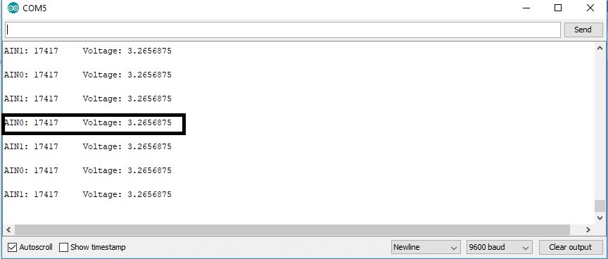
}- After uploading the code, open up Serial Monitor, you will see the output of voltage and adc0 on the serial monitor.
- For demonstration, I have connected VDD pin of ESP32 with analog channel zero.
- As you can see, we are getting close to 3.3 volts on Serial Monitor which is the operating voltage of ESP32 board, you can verify this output by measuring voltage on VDD pin of ESP32 with the help of voltmeter.

Code working
The first two lines add the library of ADS1115 and I2C communication protocol.
#include <Wire.h>
#include <Adafruit_ADS1015.h>
The next line defines the sensor type along with the address mode, we are using ADS1115. But you can also use this library with other versions of External ADC like ADS10115. The second line declares a variable of float type to store the voltage value.
Adafruit_ADS1115 ads(0x48);
float Voltage = 0.0;
Inside the setup() function, Serial.begin() function defines the baud rate of 9600 and ads.begin() function starts to read adc value.
Serial.begin(9600);
ads.begin();
Inside the loop() function , first we initialize the 16 bit long integer variable adc0 which is used to store the output of analog channel zero.
int16_t adc0;ads.readADC_SingleEnded(0) function reads the ADC channel 0 for digital value and store this value in adc0 integer variable. The next statement converts (adc0 * 0.1875)/1000 ADC’s value into the voltage stores it in the Voltage variable. One thing to note here is that 0.1875 is the resolution of ADS1115 ADC module.
adc0 = ads.readADC_SingleEnded(0);
Voltage = (adc0 * 0.1875)/1000;
Serial.print() functions prints the value of ADC and voltage on serial monitor. The delay() function adds a delay of one second after every reading.
Serial.print("AIN0: ");
Serial.print(adc0);
Serial.print("\tVoltage: ");
Serial.println(Voltage, 7);
Serial.println();
delay(1000);
In summary, in this tutorial, we have discussed the following concepts:
- Introduction to ADS1115 external I2C based ADC
- How to use it with ESP32
- How to measure voltage with ADS1115 and ESP32
You can check ESP32 projects also: