Automatic Transfer Switch for Generator (original) (raw)
Automatic transfer switch for a generator: In this project, you will learn about the most commonly used circuit for automatic transfer switches in small power generators. There are many automatic transfer switches available in the market, ranging from expensive to cheap. The price difference is due to the type of technology used. Two types of automatic transfer switches can be found: analog electronics-based and digital electronics-based.
Analog electronics-based transfer switches utilize analog electronics components such as operational amplifiers, comparators, transistors, diodes, and mechanical relays. However, they do not include a digital display. On the other hand, digital automatic transfer switches are more commonly used nowadays. They utilize liquid crystal digital displays to show current and voltage values to the user. Additionally, they indicate the status of the AC main power and generator, indicating which power source is currently feeding the load. You can incorporate as many functionalities as needed. Here are some examples:
- Monitoring current and voltage values
- Indicating the status of the AC main power and generator
- Providing real-time information to the user
In this project, I will discuss a digital automatic transfer switch and give you a brief idea about its circuit diagram and programming. I will discuss the following things?
- What is an automatic transfer switch for a generator?
- Main components
- Circuit diagram
- How to write code for an automatic transfer switch?
What are Automatic Transfer Switches?
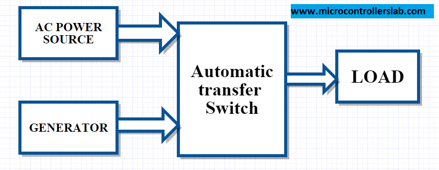
As its name suggests, an automatic transfer switch transfers the load from one power source to another in electrical terms. In this project, we use an automatic transfer switch to transfer the load between the AC main power and the generator in case either power source fails. We use automatic transfer switches for generators to automatically turn on the generator when the main power source is not available. We also use them to transfer the load to the generator after the generator’s transient period. The block diagram below illustrates an automatic transfer switch.
block diagram of the automatic transfer switch of the generator
The above block diagram is self-explanatory, but if you still do not feel comfortable, let me know with your comments.
Automatic transfer switches main components
Automatic transfer switches (ATS) have several main components that work together to ensure seamless transfer of power between different sources. These components include:
Measurement of the AC voltage from the main AC power supply from Wapda and the output of Generator A is used to sense whether the AC supply from Wapda is available or not. You should possess knowledge about how to measure alternating voltage with the assistance of a microcontroller. If you are not familiar with how to measure AC voltage using a microcontroller, please refer to the following article:
- AC voltage measurement using pic microcontroller
- The microcontroller measures AC voltages from the AC main power source and the generator. It takes necessary actions based on the availability or non-availability of either source. It also displays digital values of voltage and current on a liquid crystal display.
- A liquid crystal display is used to digitally display current and voltage values. It also shows the status of both sources.
- Relays transfer from one source to another based on actions performed by a microcontroller, subject to the availability of sources.
Circuit Diagram
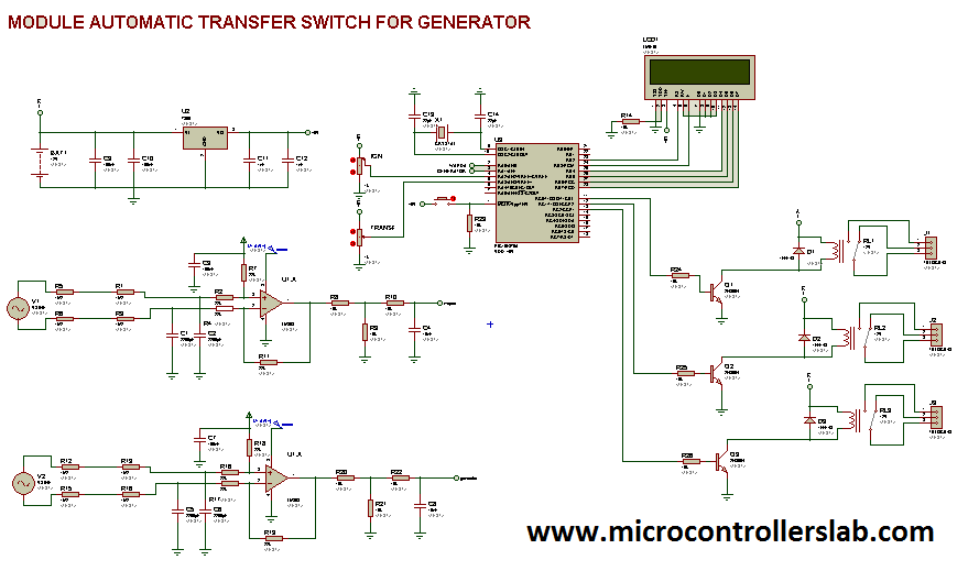
The circuit diagram of ATS using a PIC microcontroller is shown below. We have used a PIC microcontroller to measure voltage and to take necessary actions on relays.
The PIC microcontroller continuously monitors the utility power parameters using the AC voltage measurement sensors. If it detects a voltage drop, frequency deviation, or other anomalies indicating a power outage or instability, it triggers the relay to switch to the generator power source. The microcontroller also monitors the utility power restoration. Once the utility power stabilizes and meets the predefined criteria, the ATS switches back to the utility power.
Additionally, the system can include safety features, such as delay mechanisms to avoid rapid switching, and a manual override to allow manual control in specific situations. The LCD display and user interface elements provide valuable feedback to the user, indicating the current power source and any relevant information.
This ATS setup improves the reliability of backup power systems, ensuring a quick and automated response to power interruptions, which is crucial for applications where uninterrupted power is essential, such as data centers, hospitals, or critical infrastructure.
circuit diagram of automatic transfer switch for generator
Hire us to write firmware for you, contact us at: microcontrollerslabhub@gmail.com
Conclusion
In conclusion, an automatic transfer switch is an essential component in small power generators to ensure a seamless transfer of load between the AC main power and the generator. It allows for the automatic activation of the generator in the event of a power failure and transfers the load to the generator after the transient period. The most commonly used type of automatic transfer switch is the digital electronics-based switch, which incorporates functionalities such as monitoring current and voltage values and providing real-time information to the user through a digital display. By utilizing main components like microcontrollers, liquid crystal displays, and relays, the automatic transfer switch system improves the reliability of backup power systems, making it indispensable for critical applications like data centers and hospitals. Overall, understanding the concept, components, and circuit diagram of an automatic transfer switch is crucial for engineers and technicians involved in power management and backup systems.
You may also like to read:


