Boost converter using IR2110 and pic microcontroller (original) (raw)
Boost converter using IR2110 and pic microcontroller, In this article I am going to post my design of boost converter ? In this article, you will learn what is boost converter? How to design boost converter? How to use MOSFET as a switch in boost converter and how to drive this MOSFET which is connected in low side configuration. Let’s start this article with the basic understanding of boost converter and then I will move forward to circuit diagram of boost converter using 1R2210 MOSFET Gate driver and its functionality.
Preliminary Concepts
Note: In this article, I am just discussing practical aspects to make boost converter . I assume that you know about theoretical calculations of boost converter design and its basic working. If you don’t know about it I recommend you to go through any power electronics book and read chapter on dc to dc converters.
Boost Converter Circuit Diagram
Boost converter is basically a regulator which is used to step up dc voltage without transformer. In other words, it is step up transformer for dc voltage. A basic circuit diagram of boost converter is given below.
circuit diagram of boost dc to dc converter
But this circuit diagram is not full circuit diagram according to practical aspects. Because Switch shown in figure below should be replaced with any semiconductor device like transistor, MOSFET and IGBT. Selection of any one of these components as a switch depends on voltage and current rating of any converter. To use these components we also need driver circuits, For example if you are using MOSFET as a switch, then MOSFET may be used as a low side switch or high side switch that’s why you need a driver circuit. In this article, we are using IR2110 MOSFET gate driver IC**.**
Boost Converter Example
Now I will take one example of boost converter and will show you its circuit diagram which includes all practical aspects which you need to make a boost converter. For example, we want to make a boost converter which input voltage is 12V and output voltage is 20 V at 100Khz frequency. The average load current is .5 A . By using these values and with the help of formula’s of boost converter you can easily calculate values of inductor and capacitor. I am not going to discuss it here. Because there are a lot of basics available on power electronics from where you can read method to calculate values of inductor and capacitor. For example, we calculated following values :
L = 150uH
C = 33uF
For boost converter formula to calculate duty cycle or in other word on/off time of MOSFET is given below
out put voltage = input voltage / ( 1 – K ) ; where K is duty cycle
So by putting values of our example
20 = 12 / 1 – k ;
k = .4 or 40 %
So duty cycle of MOSFET is 40 % to get output voltage of 20 V. To get regulated DC output voltage you should use feedback . For example, if input voltage increases, output voltage will also increase according to above-given formula of duty cycle. But to maintain output votage constant duty cycle should be reduced equal proportion. For this purpose you need to used microcontroller and you should learn how to used microcontroller for PWM generation and to generate PWM with variable duty cycle. If you want to know about it check following article :
What is pulse width modulation ?
Pule width modulation using pic microcontller
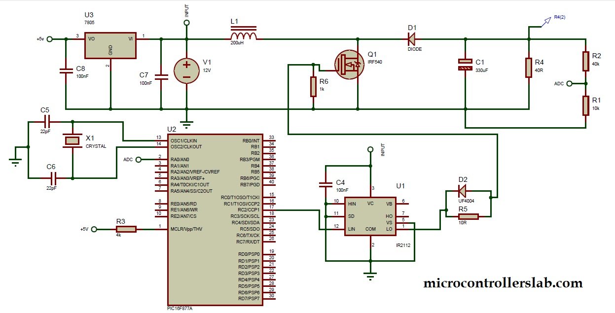
Circuit diagram of boost converter
Circuit diagram of dc to dc boost converter is given below . Diode D1 should be selected according to average load current. For example in this example average load current is .5 Ampere. So D1 should have at least 1 ampere. Similarly MOSFET should also be selected according to voltage and current rating of your design requirement.
circuit diagram of boost dc to dc converter using pic microcontroller
Mosfet is used as a low side configuration . because load is connected to drain of MOSFET. A voltage divider is used to lower voltage to less than 5 volt and then fed to microcontroller ADC pin . Because microcontroller can not read voltage more than 5 volt. This voltage measurement is used to set duty cycle in case of voltage fluctuation at the output. PIC16F877A microcontroller is used to generate PWM. you should have a knowledge about pic microcontrollers and its programming to write code for PWM and voltage measurement of above circuit diagram.
code of boost converter
After reading this article, you can write your own code, but if you need code you can contact me through email.


