digital clock ds1307 circuit & project using pic microcontroller (original) (raw)
Digital clock using ds1307 and PIC microcontroller
Digital clock using ds1307 and pic16f877a microcontroller is designed in this project. Digital clock using ds1307 displays time and date on LCD. PIC16F877A microcontroller is used to design digital clock. I2C communication protocol is used to read time and date from digital clock ds1307. PIC16F877A microcontroller is interfaced with LCD to display time and date. Digital clock ds107 use I2C serial communication proctol to send data to microcontroller. pic16f877a microcontroller receives data from ds1307 through I2C serial communication protocol. I will discuss it detail in later part of this article. Before reading this article further, you should know how to interface LCD with PIC16F877A microcontroller. If you don’t know, I recommend you to read following article first.
Digital clock DS1307
DS1307 is an integrated circuit based real time clock. It counts minutes, seconds, hours, date of month, days and years. It also have functionality to include leap year compensation up to 2100. It is binary coded decimal clock (BCD). This clock operates in either in 12 hour or 24 hour format. Indication of Am and Pm can also be included on LCD display through programming. It also have automatic power failure circuit. Automatic power failure circuit detects power failure and switch to 3 volt battery to keep record of time. It have battery back up. Battery back up is used to keep record of time in case of main power failure. It have 56 bytes non-volatile RAM for data storage. DS1307 use two wire serial communication I2C. It consumes very less power and current in the order of 500nA. It can operate in harsh temperature environment in the range of -40ºC to +85°C.
Digital clock DS1307 Pin configuration
It is 8-pin DIP IC. Pin configuration of DS1307 is given below:


Description of each pin is given below:
- SQW/OUT : Square wave and output driver pin
- SCL: Serial clock used for I2C communication
- SDA : Serial data pin for I2C serial communication
- GND: Ground pin of power supply is connected with this pin
- VBAT : It is 3 volt back up battery. It is use in case of main power failure
- X1 and X2 : 32.768 crystal connects with these pins
- Vcc : Main power supply connects with this pin
Digital clok DS1307 interfacing with microcontroller
Now I will discuss how to interface digital clock ds1307 with microcontroller. Basic block diagram of digital clock interfacing with microcontroller is given below:

In I2C serial communication, one device acts as a slave and other device acts as a master. Slave only respond to instructions of master. Slave can not give instructions to master. Digital clock DS1307 acts as a slave and respond to instructions of microcontroller. Built in register in ds1307 is used to respond to instructions of microcontroller. As shown in above circuit diagram, SCL pin of ds1307 is connected to SCL pin of microcontroller. It is used to synchronize serial data on serial wire. SCL stands for serial clock input. SDA stands for serial data input/output. SDA pin of ds1307 is connected with SDA pin of microcontroller. SDA is used as a serial data input or output for 2 wire serial communication. SDA pin of ds1307 is open drain that is why its required external pull up resistor as shown in figure above. Standard 32.876KHz quartz crystal is used with real time clock ds1307.
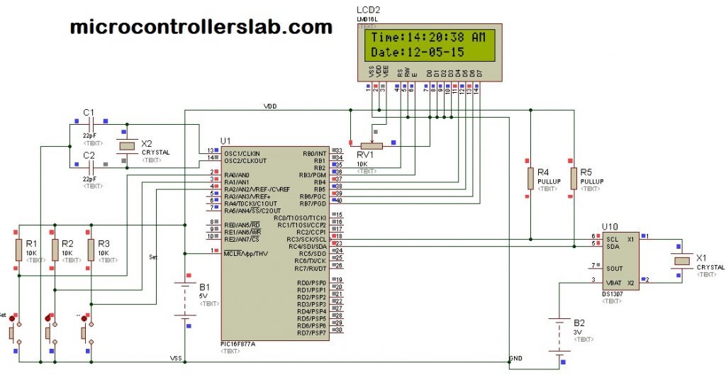
Circuit diagram of digital clock ds1307 using pic microcontroller
Circuit diagram of digital clock ds1307 using pic mirocontroller is given below. DS1307 real time clock is interfaced with PIC16F877A microcontroller. Instructions for interfacing real time clocl ds130 is given. 3 volt battery is used as back up which is used in case of main power supply faliure.PIC16F877A microcontroller fetch time and date values from DS1307 real time clock. After doing some calculations through programming, PIC16F877A microcontroller displays time and date on LCD.
 Code of digital clock DS1307 using pic microcontroller

Code for real time clock using DS1307 and pic microcontroller is written using Mikro C pro compiler. Necessary comments are also made in code for your understanding.


If you need code for digital clock DS1307 using pic microcontroller, comment on this post with your email address. If you feel any issue while designing digital clock project, let me know with your comments.