Digital humidity sensor using PIC microcontroller (original) (raw)
Digital humidity sensor with LCD display using PIC microcontroller
Digital humidity sensor with LCD display is used to measure the relative percentage of water vapors in air. HS1101 capacitive humidity sensor is interfaced with PIC16F877A microcontroller to measure humidity and LCD is used to display percentage humidity in the air. For humans, there is a certain limit for water vapors presence in the air. Above that limit relative humidity may cause problems to human health.
Applications of digital humidity sensors
Humidity sensors have much application in industry and domestic areas. Humidity means the presence of water vapors in air. Percentage of water vapors in the air should be within safety limit. Otherwise, It has harmful physical and chemical effects on human beings and also in industrial products. Humidity sensors have major applications in agriculture, chemical, oil, gas, and medical industry. For example in agriculture industry humidity sensor is used to measure moisture in fields. There are also many other application of humidity sensor. You can search for them on Google.
digital Humidity sensor selection
When you search on Google, you will come across many humidity sensors. All these humidity sensors have their advantage and disadvantage. But I used capacitive HS1101 humidity sensor in this project. What is meant by capacitive humidity sensor? All capacitive sensors give output in capacitive form. They change their capacitance with respect to change in sensing parameter like in HS1101 sensor sensing parameter is the number of water vapors in air. The reason why I used this humidity sensor? Because

- It can be used for highly sensitive applications.
- less cost
- easy to interface with a microcontroller with small extra circuitry
- No calibration is required
- It can be easily used for home appliances and industrial control system.
How to use HS1101 digital humidity sensor
HS1101 is a capacitive humidity sensor, so it can be used with a 555 timer circuit to generate a square wave of different frequency. I assume you know about the 555 timer IC and its use.

humidity sensor circuit with external circuitry
As shown in the above figure, a variable capacitor is used in place of humidity sensor for simulation purpose. Because the HS1101 simulation model is not available in Proteus. Above circuit is used as a signal conditioning circuit to convert one form of a parameter to its other proportional parameter so that it can be easily interfaced with any digital system or microcontroller. It is not possible for any microcontroller to read the change in capacitance directly. That’s why the above circuit is used to convert changing capacitance of HS1101 into square wave whose frequency changed according to change in capacitance.
I have already posted a tutorial on how to measure square wave using PIC 16F877A microcontroller. I recommend you to go through the article before going further in this project.
Now you know we can easily measure square wave frequency with the microcontroller. But now the question is how we will convert frequency back into relative humidity? There is a proper relationship between humidity and frequency. Go through data sheet of HS1101 humidity sensor to know more about HS1101 sensor.
components list for digital humidity sensor
Category,Reference,Value,Order Code Resistors,"R1",1732k, Resistors,"R2",549k, Resistors,"R3",1k, Resistors,"R4",49.9k, Resistors,"R44",10k, Integrated Circuits,"U1",NE555, Integrated Circuits,"U2",PIC16F877A, Miscellaneous,"LCD1",LM016L, Miscellaneous,"SENSOR",humidity sensor HS1101, crystal 20mhz
Circuit diagram of a digital humidity sensor
Complete circuit diagram of Digital humidity sensor with LCD display:

circuit diagram of digital humidity sensor
Simulation results using pulse generator in proteus:
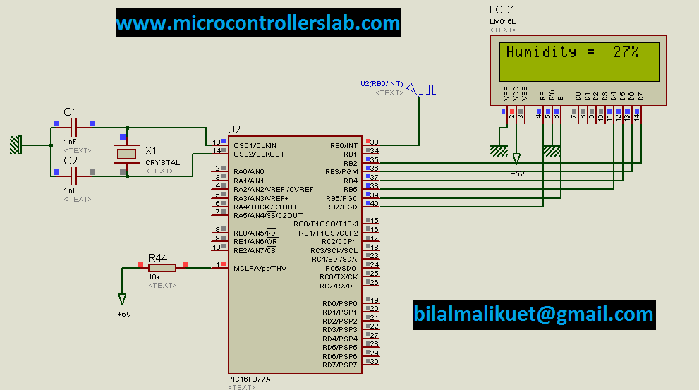
As shown in above diagram humidity is shown in percentage. 27% humidity mean air contains 27% water vapors. so you can take control actions according to your requirement. By little bit modification in this project you can also control anything according to change in relative humidity. let me know what is your requirement I will be happy to provide you solution.
Video lecture digital humidity meter
Code of digital humidity sensor measurement using pic
Code is written in mikro c for pic:
//****microcontrollerslabhub@gmail.com // LCD module connections sbit LCD_D7 at RB2_bit; sbit LCD_D6 at RB3_bit; sbit LCD_D5 at RB4_bit; sbit LCD_D4 at RB5_bit; sbit LCD_EN at RB6_bit; sbit LCD_RS at RB7_bit;
sbit LCD_D7_Direction at TRISB2_bit; sbit LCD_D6_Direction at TRISB3_bit; sbit LCD_D5_Direction at TRISB4_bit; sbit LCD_D4_Direction at TRISB5_bit; sbit LCD_EN_Direction at TRISB6_bit; sbit LCD_RS_Direction at TRISB7_bit; // End LCD module connections //frequency meter variables int value,freq,humidity; char humid[7]; //*************************************** void data_converstion(void) { IntToStr(humidity, humid); } void display1(void) {
lcd_out(1,1,"Humidity = "); lcd_out(1,13, Ltrim(humid)); Lcd_Chr_Cp('%'); Lcd_Chr_Cp(' ');
}
void interrupt(void) // high portD { if(T1CON.TMR1ON==0) { T1CON.TMR1ON=1; // turn on the timer1 INTCON.INTF = 0; // clear the interrupt flag } else if(T1CON.TMR1ON==1) { T1CON.TMR1ON=0; // turn off the timer1 value=(TMR1H<<8)|(TMR1L); INTCON.INTE = 0; //Enable RB0/INT external Interrupt freq=(5018035/value); humidity = 565 - freq/13; // freq = freq /13.18; //freq = 100 - freq; TMR1H=0; TMR1L=0; INTCON.INTE = 1; //Enable RB0/INT external Interrupt INTCON.INTF = 0; // clear the interrupt flag //freq=0; } }
void main() { long count;
count=0; TMR1H=0; TMR1L=0; // intialization of timer one prescalar and internal clock INTCON.GIE = 1; //Enable Global Interrupt INTCON.INTE = 1; //Enable RB0/INT external Interrupt OPTION_REG.INTEDG = 0; //Interrupt on rising edge ADC_Init(); Lcd_Init(); // Initialize LCD freq=0; Lcd_Cmd(_LCD_CLEAR); // Clear display lcd_cmd(_LCD_CURSOR_OFF); lcd_out(1,4,"GREEN HOUSE"); lcd_out(2,6,"SYSTEM"); delay_ms(1000); Lcd_Cmd(_LCD_CLEAR); // Clear display
while(1) {
data_converstion(); display1(); } }
If you have any problem after reading this article, comment on this post with your problem and if you need complete circuit diagram, simulation and hex file of this project, comment on this post with your email address.
If you feel this article helps you in getting some knowledge kindly don’t forget to share it with your friends on social media.
enjoy coding 🙂