Digital voltmeter using pic microcontroller (original) (raw)
In this project, a digital voltmeter using** pic microcontroller** is designed. Digital voltmeter using a pic can read the voltage from 0-40 volt. This voltmeter can read-only DC voltage. Digital AC voltmeter can also be designed using microcontrollers.
DC Voltmeter Introduction
Digital DC voltmeter is designed to measure DC voltage using the PIC16F877A microcontroller. A voltage divider circuit is used to divide voltage into two parts. To prevent more than 5 volts appearing across the pic microcontroller. Because the microcontroller can not read voltage more than 5 volts directly.
In this project, we used two types of displays namely 16×2 LCD and 4-digit seven-segment display. In the first first section, we will see how to display a value on LCD and in the second section, we will see how to display measured voltage value on a 4-digit seven-segment display.
DC voltmeter with LCD display
Liquid crystal display is interfaced with the microcontroller to display measured voltage value. Built-in analog to digital converter of pic microcontroller is used to a measured analog voltage.
Recommended Reading
Before going further in this article about digital voltmeter using pic controller, you should know how to interface LCD with pic16f877A microcontroller and how to useanalog to digital converter module of pic microcontroller. If you don’t know read the following articles first:
- LCD interfacing with PIC16F877A microcontroller
- How to use ADC module of Pic Microcontroller
- Analog voltage measurement using PIC16F877A microcontroller
Digital Voltmeter with LCD display Circuit Diagram
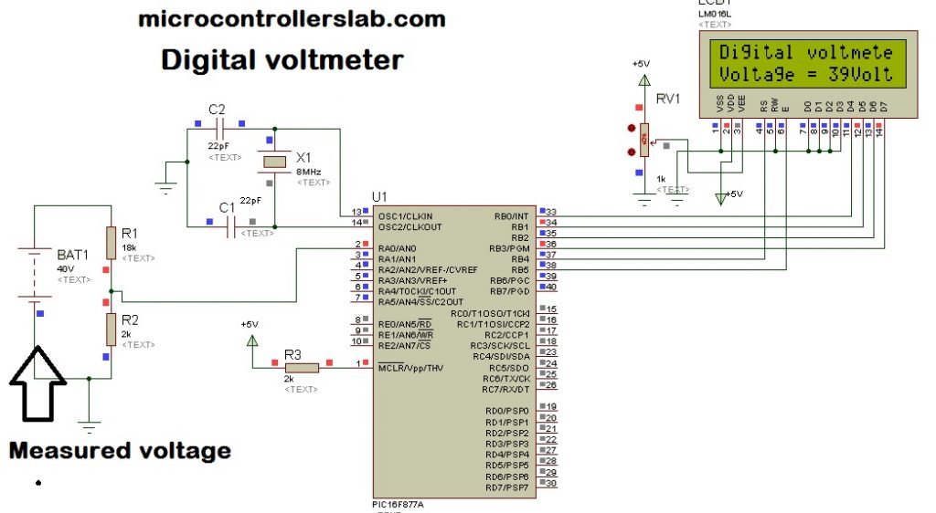
Circuit diagram of digital voltmeter using pic microcontroller and 16×2 LCD is given below. A 40-volt battery is used as a voltage source whose voltage you want to measure. PIC16F877A microcontroller can not directly read 40 volts. The voltage divider circuit using a resistor is used to step down dc voltage appearing across analog to digital converter pin of PIC16F877A microcontroller.
How to Measure Dc Voltage?
Resistor R1=18k and R2=2k are used as voltage dividers. According to voltage division formula, voltage less than 5 volts appears across pic microcontroller in the case of maximum input voltage 40 volts.
Vout = (R2 / R1+R2 ) * Vinput
Vout = ( 2 / 18+2) * 40 = 4 volt
Hence when we apply a maximum input voltage of 40 volts, only 4 volts appear across the pic microcontroller which is less than 5 volt. PIC16F877A microcontroller has seven analogs to digital converter channels. It means it can be interfaced with seven analog channels or it can measure seven analog quantities.
ADC Channel
In this project, AN0/RA0 channel of the pic16F877A microcontroller is used. ADC module of pic microcontroller converts an analog signal into binary numbers. PIC16F877A microcontroller has a 10 bit ADC. So it converts an analog signal to a 10-bit digital number which can be back converted into voltage using the following calculation in the programming of digital voltmeter.
Resolution = (Vrer+ - Vref-) / (1024 -1 ) ;ADC resolution is an important concept to discuss here. Resolution means minimum value of the analog signal for which ADC counter increment by one. For example, pic16f877A microcontroller has 10-bit ADC and it counts binary from 0-1023 for every minimum analog value of the input signal. This minimum analog value is called resolution ADC increment by one. For example, pic16f877A microcontroller has 10-bit ADC and it counts binary from 0-1023 for every minimum analog value of the input signal. This minimum analog value is called resolution.
In this project, we are taking Verf+= 5 volts and Vref- = 0 volt. Hence by using these values in the above formula, this minimum voltage will be:
resolution = (5 - 0 )/ (1023) = 4.8876 mV;It means for every analog signal of 4.87mV, ADC value increments by one.
Simulation Result
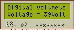
Liquid crystal display is used to display values of voltage. As shown in the figure below. The below diagram shows the result of the digital voltmeter using the pic microcontroller and LCD display.
Video lecture
Digital voltmeter Code MikroC
Now, let’s discuss how to write a program for digital dc voltmeter using a pic microcontroller. Above I have discussed the function of each component and its working in dc voltage measurement with pic microcontroller. The code for digital voltmeter is written using the MikroC Pro compiler. Voltage measured by the ADC module of PIC16F877A microcontroller can be calculated by following programming commands:
voltage = ADC_Read(0); // ADC channel zero stores value in variable voltage
voltage = (voltage * 5 * 10)/ (1024); // resolution factor and voltage divider factor
Statement one is used to reading ADC value and stores its value in variable “voltage” and in second statement voltage value is multiplied with resolution factor and voltage divider factor to convert it into actual input voltage value.
Digital Voltmeter Code with LCD Display
This code is written using MikroC for Pic compiler. Create a new project with MikroC compiler by selecting PIC16F877A microcontroller and set frequency to 8MHz. If you don’t know how create new project in mikroC, we suggest you read this post:
sbit LCD_RS at RB4_bit;
sbit LCD_EN at RB5_bit;
sbit LCD_D4 at RB0_bit;
sbit LCD_D5 at RB1_bit;
sbit LCD_D6 at RB2_bit;
sbit LCD_D7 at RB3_bit;

sbit LCD_RS_Direction at TRISB4_bit;
sbit LCD_EN_Direction at TRISB5_bit;
sbit LCD_D4_Direction at TRISB0_bit;
sbit LCD_D5_Direction at TRISB1_bit;
sbit LCD_D6_Direction at TRISB2_bit;
sbit LCD_D7_Direction at TRISB3_bit;
int Adread;
float voltage;
char volt[4];
void main() {

PORTA = 0;
TRISA = 0X01;
PORTB = 0;
TRISB = 0;
LCD_Init();
ADC_Init();
LCD_Cmd(_LCD_CURSOR_OFF);
LCD_Cmd(_LCD_CLEAR);
LCD_Out(1, 1, "Digital voltmeter");
delay_ms(1000);
while (1)
{
voltage = ADC_Read(0);
voltage = (voltage * 5 * 10)/ (1024);
inttostr(voltage,volt); // it converts integer value into string
Lcd_Out(2,1,"Voltage = ");
Lcd_Out(2,11,Ltrim(volt));
Lcd_Out(2,13,"Volt");
}
}
Code Working
Now let’s understand the working of code. First, we used ‘sbit’ to define pins connection with LCD and PIC16F877A. These lines are used to define pic microcontroller pins that will be used with 16×2 LCD.
sbit LCD_RS at RB4_bit;
sbit LCD_EN at RB5_bit;
sbit LCD_D4 at RB0_bit;
sbit LCD_D5 at RB1_bit;
sbit LCD_D6 at RB2_bit;
sbit LCD_D7 at RB3_bit;

sbit LCD_RS_Direction at TRISB4_bit;
sbit LCD_EN_Direction at TRISB5_bit;
sbit LCD_D4_Direction at TRISB0_bit;
sbit LCD_D5_Direction at TRISB1_bit;
sbit LCD_D6_Direction at TRISB2_bit;
sbit LCD_D7_Direction at TRISB3_bit;
These code lines initialize built-in library of ADC module and liquid crystal dislpay.
LCD_Init(); // intialize LCD library
ADC_Init(); // initialize ADC library
LCD_Cmd(_LCD_CURSOR_OFF); // turn off LCD cursor
LCD_Cmd(_LCD_CLEAR); // Clear whatever is written on LCD
LCD_Out(1, 1, "Digital voltmeter"); // print "Digital voltmeter"on first line and first row
delay_ms(1000); // add a delay of one second
This code is placed inside the while(1) loop function and it keeps executing. Inside this loop, ADC_Read(0) reads analog input signal value from AN0/RA0 pins and store this value into a variable “voltage”. Second line converts measured digital value back into analog voltage by multiplying voltage variable with resolution factor and voltage divider scale down factor. After that we display voltage value on LCD second line.
Before printing value on LCD, we first convert integer variable “voltage” into string by using inttostr() routine.
voltage = ADC_Read(0);
voltage = (voltage * 5 * 10)/ (1024);
inttostr(voltage,volt);
Lcd_Out(2,1,"Voltage = ");
Lcd_Out(2,11,Ltrim(volt));
Lcd_Out(2,13,"Volt");
This digital voltmeter using a pic can read voltage only between 0-40 volt. High voltage measurement voltmeter can also be designed using pic microcontroller and difference amplifier. The difference amplifier will be used to step down dc voltage instead of a voltage divider.


