HeartBeat Sensor with Arduino: Pulse Measurement (original) (raw)
In this article, we will learn how to interface a heartbeat sensor with Arduino and display the pulse rate on an LCD.
Heartbeat Sensor is used as blood pressure and body temperature are very important parameters to know for the human body. We go to doctors who use different kinds of apparatuses to determine the heart rate of a human. In this tutorial, we are going to make our own heartbeat sensor that will tell us the heart rate. We will make an Arduino based heartbeat sensor that will tell us the number of pulses in a minute when we place a finger on it.
Heart Pulse Sensor Pinout

The heart rate sensor module has three pins.

The signal will be connected to the analog pin of the Arduino, the 5V will be connected to the 5V pin of the Arduino, and the GND will be connected to the ground of the Arduino.
Working of Heartbeat Sensor
The module uses an infrared LED (IR) and a phototransistor to detect the pulse of the finger. Whenever a pulse is detected, the red LED flashes. There will be an LED on the light side of the finger and a phototransistor on the other side. The phototransistor is used to obtain the emitted flux. The resistance of the photoresistor will change when the pulses change.
Heartbeat Sensor Interfacing with Arduino
The connection diagram shows how to interface a heartbeat sensor with an Arduino. Here are the details of the connections:
- Signal (Output Pin): Connect this pin to Analog Pin A0 on the Arduino.
- 5V: Connect this pin to the 5V pin on the Arduino for power.
- GND: Connect this pin to the ground (GND) pin on the Arduino.

Heartbeat Sensor with Arduino Code
This code is for testing the measurement of heart pulses.
// Initialize the LED pin and sensor output pin
int led_Pin = 13;     // LED pin
int output_Pin = A0;  // Sensor output pin

// Initialize other variables
double alpha = 0.75;
int period = 200;
double change = 0.0;

void setup()
{
  pinMode(led_Pin, OUTPUT);    // Declare LED pin as an output
  Serial.begin(115200);        // Set the baud rate to 115200 for serial communication
}

void loop()
{
  // Initialize other variables
  static double oldValue = 0;
  static double oldChange = 0;

  // Read sensor values
  int rawValue = analogRead(output_Pin);

  // Calculate values using the formula
  double value = alpha * oldValue + (1 - alpha) * rawValue;

  // Print the sensor output value and calculated value
  Serial.print(rawValue);
  Serial.print(",");
  Serial.println(value);

  // Update oldValue for the next iteration
  oldValue = value;

  // Delay for a specified period
  delay(period);
}
Arduino Heartbeat sensor with LCD Attached
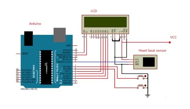
In this example, we will attach the heart pulse sensor to Arduino and an LCD. Arduino will control the whole system. It will read the pulses from the heart rate sensor module, calculate the heart rate, and display it on the LCD. The output pin of the heart rate sensor connects to pin 8 of Arduino. The LCD connects to Arduino in 4-bit mode. The VCC and GND of the sensor connect to the VCC and GND of Arduino. When we press the push button, the system will start counting the pulses.
There are many methods for calculating the heartbeat, but here we will take only five pulses and calculate the total heart rate per minute using this formula.
- Five pulse time = time2 – time1
- Single pulse time = Five pulse time / 5
- Rate = 60000 / Single pulse time;
- where time1 is the first pulse counter value
- time2 is the last pulse counter value
- rate is the final heart rate
Components
The components used for making this project are as follows.
- Arduino (we have used Arduino Uno)
- 16 x 2 LCD
- Heartbeat sensor
- Push button
Code
This code is for monitoring and displaying a heart rate using a pulse sensor. It uses an LCD display to show the heart rate in beats per minute (BPM) and uses two push buttons for control.
#include <LiquidCrystal.h> // Include the LCD library

LiquidCrystal lcd(12, 11, 5, 4, 3, 2); // Declare pins for the LCD

int in = 8;     // Declare pin 8 for sensor output
int Reset = 6;  // Declare pin 6 for the reset push button
int start = 7;  // Declare pin 7 for the start push button
int count = 0, i = 0, k = 0, rate = 0; // Initialize other variables

unsigned long time2, time1;
unsigned long time;

byte heart[8] =
{
  0b00000,
  0b01010,
  0b11111,
  0b11111,
  0b11111,
  0b01110,
  0b00100,
  0b00000
};

void setup()
{
  lcd.createChar(1, heart);
  lcd.begin(16, 2); // Start the LCD with 16 columns and 2 rows

  lcd.print("Heart Beat "); // Display "Heart Beat" on the LCD
  lcd.write(1); // Display a custom heart character
  lcd.setCursor(0, 1); // Set the cursor to the second row
  lcd.print("Monitoring"); // Display "Monitoring" on the LCD

  pinMode(in, INPUT); // Initialize the pins as input pins
  pinMode(Reset, INPUT);
  pinMode(start, INPUT);

  digitalWrite(Reset, HIGH); // Set the push button states as high
  digitalWrite(start, HIGH);
  delay(1000); // Delay for 1 second
}

void loop()
{
  if (!(digitalRead(start))) // Check if the start button is pressed
  {
    k = 0;
    lcd.clear();
    lcd.print("Please wait......."); // Display "Please wait......." on the LCD

    while (k < 5) // Apply another condition
    {
      if (digitalRead(in)) // Read from the sensor
      {
        if (k == 0)
          time1 = millis();
        k++;
        while (digitalRead(in));
      }
    }

    // Calculate the heart beat rate
    time2 = millis();
    rate = time2 - time1;
    rate = rate / 5;
    rate = 60000 / rate;

    lcd.clear(); // Clear the LCD
    lcd.print("Heart Beat Rate:"); // Display "Heart Beat Rate:" on the LCD
    lcd.setCursor(0, 1); // Set the cursor to the second row
    lcd.print(rate); // Display the heart beat rate on the LCD
    lcd.print(" ");
    lcd.write(1);
    k = 0;
    rate = 0;
  }

  if (!digitalRead(Reset)) // Check if the reset button is pressed
  {
    rate = 0;
    lcd.clear(); // Clear the LCD
    lcd.print("Heart Beat Rate:"); // Display "Heart Beat Rate:" on the LCD
    lcd.setCursor(0, 1); // Set the cursor to the second row
    lcd.write(1);
    lcd.print(rate); // Display the heart beat rate on the LCD
    k = 0;
  }
}
How Does Code Work?
The code initializes the pins for the sensor output, reset button, and start button. When the “Start” button is pressed, the code enters a monitoring mode. It reads data from the sensor connected to pin 8, calculates the heart rate based on the sensor readings, and displays it on the LCD screen. The heart rate calculation involves measuring the time between heartbeats and converting it to BPM. The LCD shows “Heart Beat” and a custom heart symbol on the top line and “Monitoring” on the bottom line. If the “Reset” button is pressed, the heart rate display is reset to zero.
In the monitoring mode, the code continually checks the “Start” button’s status. When pressed, it captures a series of sensor readings to calculate the heart rate. It displays “Please wait…….” on the LCD while capturing data, and after five measurements, it computes and displays the heart rate in BPM. If the “Reset” button is pressed, the heart rate display is reset. The code aims to provide a simple heart rate monitoring system, and you can connect a heart rate sensor to pin 8 to use it effectively. It uses an exponential moving average to smooth the sensor data for more accurate readings.
Conclusion
In conclusion, the heartbeat sensor is a cost-effective sensor for monitoring and measuring heart rate. It offers a cost-effective and DIY solution for individuals who want to keep track of their heart health. By utilizing an infrared LED and phototransistor, the sensor detects pulse and displays the number of pulses per minute. With the help of an Arduino, the sensor can be easily interfaced and integrated into various projects. Additionally, we have seen a pinout diagram, connection diagram, and sample code for both basic heart pulse measurement and heart rate monitoring with an LCD display.
Related content:
- MAX30102 Pulse Oximeter and Heart Rate Sensor with ESP8266
- MAX30102 Pulse Oximeter and Heart Rate Sensor with ESP32
- MAX30100 Pulse Oximeter and Heart Rate Sensor with ESP32
- MAX30102 Pulse Oximeter and Heart Rate Sensor with Arduino
- MAX30100 Pulse Oximeter and Heart Rate Sensor with ESP8266
- AD8232 ECG Module with Arduino – Heart Rate Monitor
- Monitor Heart Rate using Pulse Sensor and ESP8266 NodeMCU
- Monitor Heart Rate using Pulse Sensor and ESP32
- Monitor Heart Rate using Pulse Sensor and Arduino
- Heart beat pulse sensor interfacing with pic microcontroller
| Arduino Components | Amazon Links |
|---|---|
| Arduino Starter Kit | Buy Now |
| Arduino Development Kit | Buy Now |
| Arduino Smart Robot Car Kit V4 | Buy Now |
| Arduino Sensors Kit | Buy Now |