Interfacing of MQ135 Gas Sensor with Arduino (original) (raw)
In this tutorial, we will learn how to interface MQ-135 Gas Sensor with Arduino Board. We will explore what is a gas sensor, how it works, its pin configuration and how to interface it with Arduino.
What is MQ-135 gas sensor?
MQ-135 sensor belongs to the MQ series that are used to detect different gasses present in the air. The MQ-135 sensor is used to detect gases such as NH3,NOx, alcohol, Benzene, smoke,CO2 ,etc. steel exoskeleton houses a sensing device within the gas sensor module.
how does it work?
Through connecting leads, the sensing element is exposed to current. The gases that come close to the sensing element are ionized and absorbed by the sensing element as a result of this current, which is known as heating current. This affects the resistance of the sensing element, hence changing the value of the current leaving it.


When no gas is present, digital output is 1 and analog output gives 1023 max value. When gas is present, digital output is 0 and analog output is much less than 1023.
Using potentiometer on chip we can control the turning OFF point of digital pin at some value of analog pin. The sensor needs a load-resistor at the output to ground. Its value could be from 2kOhm to 47kOhm. The lower the value, the less sensitive is the sensor. The higher the value, the less accurate is sensor for higher concentrations of gas. If only one specific gas is measured, the load-resistor can be calibrated by applying a known concentration of that gas. If the sensor is used to measure any gas (like in a air quality detector) the load-resistor could be set for a value of about 1V output with clean air. Choosing a good value for the load-resistor is only valid after the burn-in time
MQ-135 Gas Sensor Module Overview
MQ-135 gas sensor module features both analog output fetched from its AO pin and digital output fetched from its DO pin.
The analog output voltage lies between 0-5V where the output voltage increases relatively with the concentration of gas vapors coming in contact with the sensor. Under standard conditions, this output voltage from the sensor is directly proportional to the concentration of CO2 gas in PPM. This output voltage is converted to a digital value (0-1023) via the analog to digital converter in Arduino. This value is equal to the gas concentration in PPM.
Whereas the digital output voltage (0/1) is obtained after passing the analog output from LM393 comparator situated at the backside of the sensor module. The in built potentiometer is manually calibrated to change the sensitivity of the digital output and set a threshold value. This is done with the help of the DOUT LED. When the concentration of gas vapors will be greater than the threshold value set, the digital output will be LOW. This will be easily monitored when the DOUT LED lights up. Additionally, rotating the potentiometer clockwise results in a higher sensitivity.
The MQ-135 gas sensor module’s front side consists of the sensor enclosed in a steel exoskeleton. This is to protect the sensor as it gets heated up over time and will eventually come in contact with the gas vapors.
The backside of the module consists of two LEDs: DOUT LED (lights when DO is LOW) and the power LED (lights when the module is powered on), an LM393 comparator, and a potentiometer.

Specifications
The table below shows some key specifications of the MQ-135 sensor module:
| Feature | Description |
|---|---|
| Operating Voltage | 2.5-5.0V |
| Detecting Concentration | 10ppm-300ppm for NH310ppm-1000ppm for Benzene10ppm-300ppm for Alcohol |
| Load Resistance | Adjustable |
| Heater Resistance | 33Ω ± 5% |
| Heater Consumption | less than 800mW |
| Operating Temperature | -10 to 45°C |
Pinout
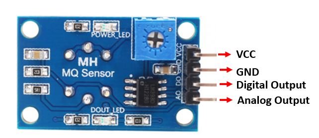
The MQ-135 sensor module consists of four pins namely VCC, GND, DO, and DO. The table below gives a brief description of them.
| Pin | Description |
|---|---|
| VCC | Positive power supply pin that powers up the sensor module. |
| GND | Reference potential pin. |
| AO | Analog output pin. It generates a signal proportional to the concentration of gas vapors coming in contact with the sensor. |
| DO | Digital Output pin. It also produces a digital signal whose limit can be set using the in-built potentiometer. |
The table below shows the connections you need to make between the MQ3 sensor module and Arduino using both the analog output and the digital output pins of the sensor.
| MQ-135 Module | Arduino |
|---|---|
| VCC | 5V |
| GND | GND |
| AO | A0 |
| DO | Pin 2 |
Connect MQ-135 sensor’s VCC pin with 5V terminal of Arduino UNO. This will power up the sensor.
Additionally, we will connect the analog pin AO with A0 and DO with Pin 2 of Arduino UNO. Both the devices will be commonly grounded.
Follow the connection diagram below, to connect your devices accordingly.
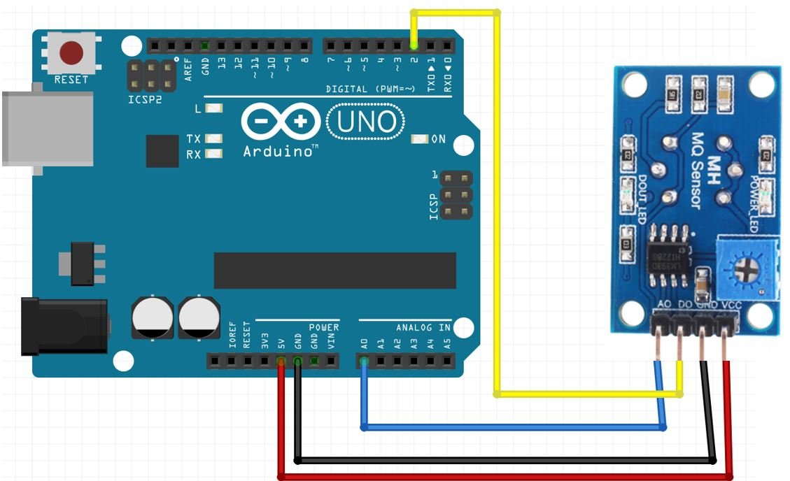
Arduino UNO with MQ-135 Module using both digital and analog outputs
MQ-135 Gas Detection Arduino Sketch
Open your Arduino IDE and go to File > New. Copy the code below in that file.
This sketch will read both the analog and digital outputs of the sensor. If the analog output is greater than 400 then an LED connected at Arduino pin 2 will turn ON. Otherwise, turn the LED OFF and print both the analog and digital output readings on the serial monitor.
int sensorValue;
int digitalValue;

void setup()
{
  Serial.begin(9600); // sets the serial port to 9600
  pinMode(13, OUTPUT);
  pinMode(2, INPUT);
}

void loop()
{
  sensorValue = analogRead(0); // read analog input pin 0
  digitalValue = digitalRead(2);
  if (sensorValue > 400)
  {
    digitalWrite(13, HIGH);
  }
  else
    digitalWrite(13, LOW);
  Serial.println(sensorValue, DEC); // prints the value read
  Serial.println(digitalValue, DEC);
  delay(1000); // wait 100ms for next reading
}
How the Code Works?
Create two int variables to hold the analog and digital output readings.
int sensorValue;
int digitalValue;
Inside the setup() function, we will open the serial communication at a baud rate of 9600. Then configure pin2 connected with the DO pin of the sensor as an input and pin13 connected with the LED’s anode pin as an output.
void setup()
{
  Serial.begin(9600); // sets the serial port to 9600
  pinMode(13, OUTPUT);
  pinMode(2, INPUT);
}
In the infinite loop(), we will use analogRead() on the A0 pin and save the value in ‘sensorValue.’ Likewise, we will read the digital output on pin2 using digitalRead() and save the value in ‘digitalValue.’ Next, using an if-else statement we will check if the analog reading is greater than 400 or not. If it is then turn the LED ON. Otherwise, leave the LED OFF and display the current analog and digital readings in the serial monitor.
void loop()
{
  sensorValue = analogRead(0); // read analog input pin 0
  digitalValue = digitalRead(2);
  if (sensorValue > 400)
  {
    digitalWrite(13, HIGH);
  }
  else
    digitalWrite(13, LOW);
  Serial.println(sensorValue, DEC); // prints the value read
  Serial.println(digitalValue, DEC);
  delay(1000); // wait 100ms for next reading
}
Demonstration
To see the demonstration of the above code, upload the code to Arduino. But, before uploading code, make sure to select the Arduino board from Tools > Board and also select the correct COM port to which the Arduino board is connected from Tools > Port.

On the serial monitor, you can see the values of the analog pin being detected. Currently, in my case, they are around about 150 which indicates normal air.
- Normal air returns approximately 100-150
- Alcohol returns approximately 700
- Lighter gas returns approximately 750
Watch the video demonstration below:
You may also like to read:
- Interface MQ3 Alcohol Sensor Module with Arduino
- MQ137 Ammonia Gas Sensor Interfacing with Arduino
- Interface MQ4 Methane Gas Sensor with Arduino
- MQ-2 gas sensor interfacing with pic microcontroller
| Arduino Components | Amazon Links |
|---|---|
| Arduino Starter Kit | Buy Now |
| Arduino Development Kit | Buy Now |
| Arduino Smart Robot Car Kit V4 | Buy Now |
| Arduino Sensors Kit | Buy Now |