LSM303 Triple-Axis Accelerometer/Magnetometer Module with Arduino (original) (raw)
LSM303 is a complete system-in-package module introduced by ST Electronics. The device is a small, high-performance module integrated with a triple-Axis accelerometer to measure the tilt angle or movement of an object with respect to the Earth. It is also integrated with a magnetometer to detect the direction of the object by measuring the magnetic strength. The module is MCU-friendly and communicates using the I2C protocol.
LSM303 Module Introduction
The module has two modes i.e. standard and fast mode with 400kHz of max frequency with a little power consumption. It has two interrupts for free-fall detection that are user-programmable. The sensitive device is very handy in small embedded projects like a compass, position, orientation detection, linear acceleration, and consumer devices mainly VR gaming. The tutorial describes the pinout, features, specifications, interfacing, and applications.
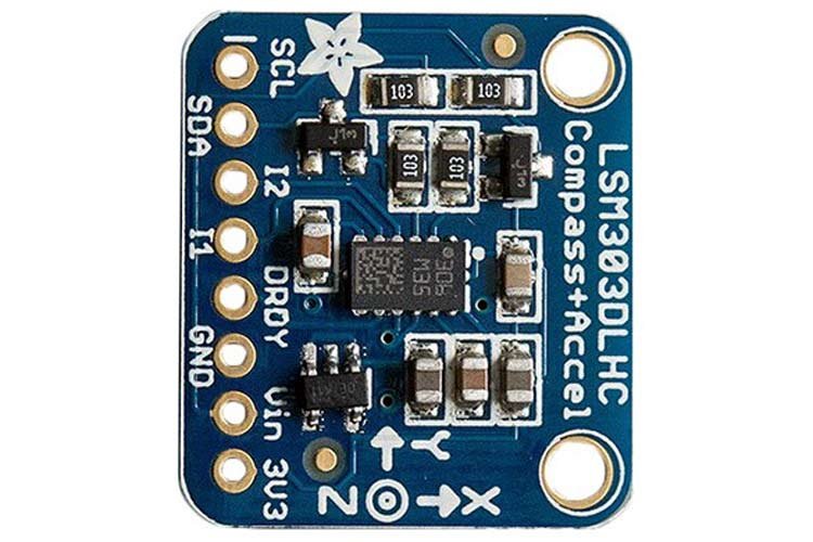
LSM303 Components
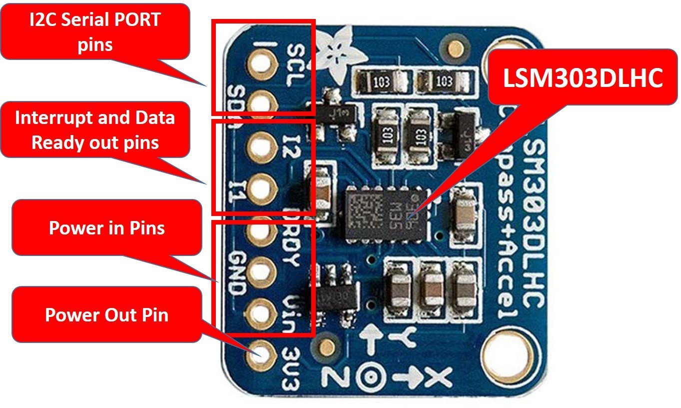
The image shows the components of the LSM303 module:

I2C Bus: The Inter-Integrated Bus will serve the purpose of data transmission between the module and microcontroller unit.
Power Block: The power block will power up the module for the operation.
DRDY: The data ready pin is responsible for triggering the interrupts.
LSM303DLHC: The fundamental component of the module processes and transfers information.
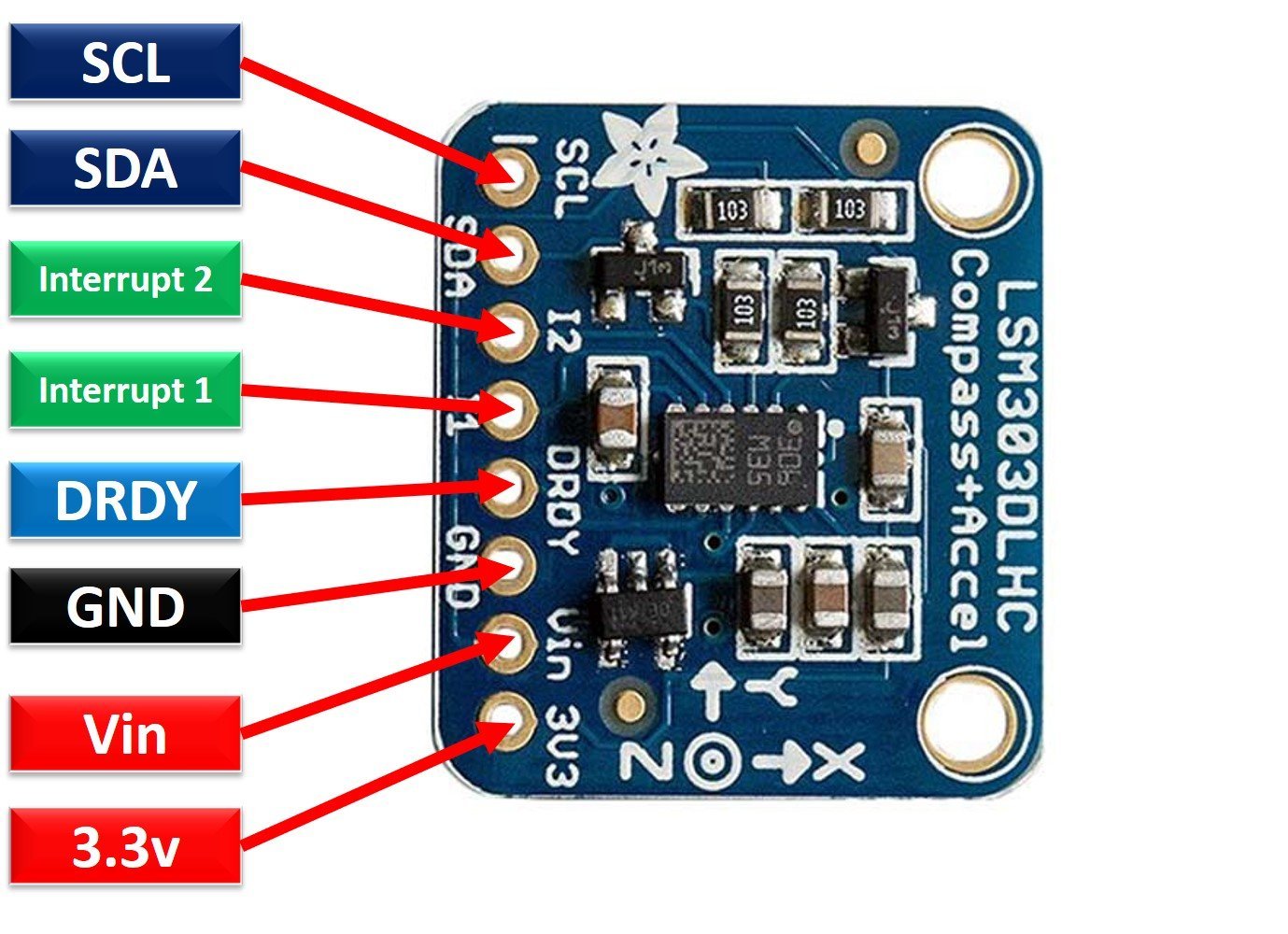
LSM303 Pinout
The following diagram shows the pinout of the LSM303 Triple-Axis Accelerometer/Magnetometer module:
Pin Configuration
LSM303 Triple-Axis Accelerometer/Magnetometer chip has a total of 14 pins but only 8 of them are extended to the board. The pin configuration detail in tabular is mentioned below:
| Number | Pin Name | Function |
|---|---|---|
| 1 | VDD_I/O | Power Supply for digital I/O pin |
| 2 | SCL | Serial Clock pin |
| 3 | SDA | Serial Data pin |
| 4 | INT2 | Interrupt2 pin |
| 5 | INT1 | Interrupt1 pin |
| 6 | C1 | Capacitor Connection pin (C1) |
| 7 | GND | Reference potential pin |
| 8 | RESERVED | Not connected |
| 9 | DRDY | Data Ready pin |
| 10 | RESERVED | Ground Connected |
| 11 | RESERVED | Ground Connected |
| 12 | SETP | SR Capacitor Connection pin (C2) |
| 13 | SETC | SR Capacitor Connection pin (C2) |
| 14 | VDD | Positive Power Supply pin |
- VDD_I/O: It is a dedicated power supply for the input/output pins to determine low/high output.
- SDA/SCL: Serial data line and serial clock are responsible for information transfer using I2C protocol.
- INT pins: Interrupt pins are temporary subroutines that MCU processes before resuming to normal executions.
- Capacitors pins: These pins are connections of decoupling capacitors for the power supply.
- DRDY: This pin triggers the interrupts and helps in simplifying data synchronization.
- Reserved: These pins must not be connected.
LSM303 Features and Specifications
Following are some of the features of the LSM303 Triple-Axis Accelerometer/Magnetometer module:
| Features and Peripherals | Availability |
|---|---|
| Structure | MEMS |
| I2C Data Rate | 100 kHz |
| I2C Fast Data Rate | 400 kHz |
| I2C Data Hold Time | 3.45 us |
| I2C Fast Data Hold Time | 0.9 us |
| FIFO buffer | Yes |
| Magnetic Full Scale Range | ±1.3 – ±8.1 gauss |
| Linear Acceleration Full Scale Range | ±2g/±4g/±8g/±16g |
| I2C | Yes |
| Operating Voltage | 2.16 – 3.6 Volts |
| Data Output Resolution | 16-bit |
| VDDIO | Yes |
| Digital Output Temperature Sensor | Yes |
| DRDY | 2 |
| Programmable Interrupts | 2 |
| Zero-g Offset | Yes |
| Package Type | LGA-14 |
- It is a three-channeled accelerometer and magnetometer.
- The module requires low voltage ranging from 2.16 – 3.6 Volts.
- LSM303 can work in two modes i.e. standard mode and fast mode.
- It has a 6D/4D orientation detection.
- The module is integrated with a temperature sensor and a first-in-first-out memory structure.
- LSM303 has an embedded high-resolution Analog-to-Digital converter.
- LSM303 has a Zero-g Offset to measure the deviation of the output.
- The module has a high linear acceleration making it a sensitive device.
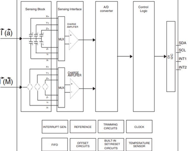
LSM303DLHC Chip Block Diagram
The block diagram of the LM303 Triple-Axis Accelerometer/Magnetometer module showing the connectivity of the IC and peripherals is as follows:
How to interface LSM303 with Microcontroller?
LSM303 is quite easy to interface with any microcontroller unit which has an I2C protocol port. The following diagram shows that how to connect LSM303 module with any microcontroller over an I2C bus.

The following steps should be followed to connect MCU to LSM303:
- Connect the power supply pins of the MCU and the module.
- Also, connect the SDA and SCL pins of the module to the SDA and SCL pins of the MCU for data transmission.
- Make a connection of the interrupts of LSM303 and MCU together.
- DRDY pin to any Digital pin of the MCU.
- Connect pull-up resistors in the circuit if the module or MCU does not have any.
- Make sure to make the connections using long wires so that when the module is moved, it doesn’t disturb the rest of the circuitry.
- The module should be kept away from other magnets to avoid errors in the readings.
LSM303 Module Interfacing with Arduino
This portion of the tutorial will describe an example code of LSM303 with Arduino UNO.
Connection Diagram
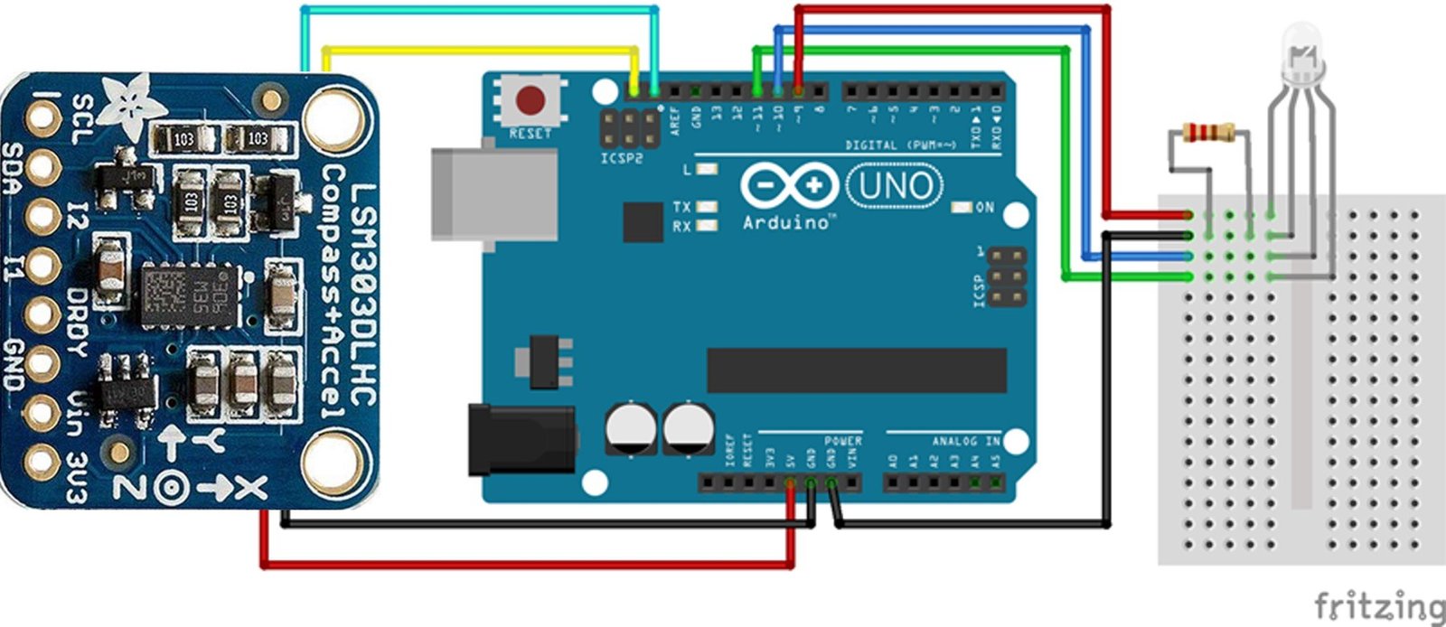
The code is about using the magnetometer of the LSM303 and making a compass that will guide the directions by displaying different RGB colors.
- Power supply pins Vin and GND of LSM303 module to 5V and GND of the Arduino respectively.
- Connect SDA and SCL of the module to the ICSP2 headers of the Arduino UNO.
- Attach RGB LED and resistor to 5V, GND, PWM pin 9, 10 and 11 of the Arduino.
The wiring diagram is presented for the visual:
Arduino Library
First download the Arduin library for LSM303 from this link and add it to Arduino IDE.
Arduino Code
#include <Wire.h>
#include <Adafruit_Sensor.h>
#include <Adafruit_LSM303_U.h>


/* Assign a unique ID to this sensor at the same time */
Adafruit_LSM303_Mag_Unified mag = Adafruit_LSM303_Mag_Unified(12345);


// OUTPUT: Use digital pins 9-11, the Pulse-width Modulation (PWM) pins
// LED's cathodes should be connected to digital GND
int redPin = 9;   // Red LED,   connected to digital pin 9
int grnPin = 10;  // Green LED, connected to digital pin 10
int bluPin = 11;  // Blue LED,  connected to digital pin 11


// Program variables
int redVal = 0;   // Variables to store the values to send to the pins
int grnVal = 0;
int bluVal = 0;

int magnetometer = 0;
int magVal = 0; //Variable to store the input from the magnetometer


// Pi for calculations - not the raspberry type
const float Pi = 3.14159;

// This is the desired direction of travel
// expressed as a 0-360 degree compass heading
// 0.0 = North
// 90.0 = East
// 180.0 = South
// 270 = West
const float targetHeading = 0.0;


void setup()

{

  Serial.begin(9600);
  Serial.println("Magnetometer Test"); Serial.println("");

  /* Initialise the sensor */
  if(!mag.begin())
  {
    /* There was a problem detecting the LSM303 ... check your connections */
    Serial.println("Ooops, no LSM303 detected ... Check your wiring!");
    while(1);
  }

  pinMode(redPin, OUTPUT);   // sets the pins as output
  pinMode(grnPin, OUTPUT);
  pinMode(bluPin, OUTPUT);

}


void loop(void)

{ /* Get a new sensor event */
  sensors_event_t event;
  mag.getEvent(&event);


  // Calculate the angle of the vector y,x
  float heading = (atan2(event.magnetic.y,event.magnetic.x) * 180) / Pi;  // Normalize to 0-360


  if (heading < 0)

  { heading = 360 + heading;
  }


  magVal = heading;  // read the magnetometer

  Serial.print("mag: "); Serial.print(magVal); Serial.print(" # ");


  if (magVal < 91)  // Lowest fourth of the magnetometer's range (0-90)

  { magVal = (magVal * 3) / 4; // Normalize to 0-68

    redVal = 69 - magVal;  // Red from full to off
    grnVal = magVal;        // Green from off to full
    bluVal = 1;             // Blue off

    Serial.print("1: "); Serial.print(redVal); Serial.print(":");Serial.print(grnVal);
    Serial.print(":"); Serial.println(bluVal);
  }


  else if (magVal < 181) // Lower middle fourth of magnetometer's range (91-180)

  { magVal = ( (magVal-91) * 3) / 4; // Normalize to 0-68

    redVal = 1;            // Red off
    grnVal = 69 - magVal; // Green from full to off
    bluVal = magVal;       // Blue from off to full

    Serial.print("2: "); Serial.print(redVal); Serial.print(":");Serial.print(grnVal);
    Serial.print(":"); Serial.println(bluVal);
  }


  else if (magVal < 271)// Upper middle fourth of magnetometer"s range (181-270)

  { magVal = ( (magVal-182) * 3) / 4; // Normalize to 0-68

    redVal = 1;           // Red off
    grnVal = 1;            // Green off
    bluVal = 69 - magVal; // Blue from full to off

    Serial.print("3: "); Serial.print(redVal); Serial.print(":");Serial.print(grnVal);
    Serial.print(":"); Serial.println(bluVal);
  }


  else  // Upper fourth of magnetometer"s range (271-360)

  { magVal = ( (magVal-272) * 3) / 4; // Normalize to 0-68

    redVal = 1;       // Red of
    grnVal = 1;       // Green off
    bluVal = 1;       // Blue off

    Serial.print("4: "); Serial.print(redVal); Serial.print(":");Serial.print(grnVal);
    Serial.print(":"); Serial.println(bluVal);
  }


  analogWrite(redPin, redVal);   // Write values to LED pins
  analogWrite(grnPin, grnVal);
  analogWrite(bluPin, bluVal);

}
How Code Works?
The code will be explained in snippets for a better understanding of the code.
Include Libraries
Include libraries and variable declaration: First, download the concerned Arduino libraries and install them to the Arduino IDE. Now, include these libraries in the sketch for interfacing LSM303.
Define Pins
Define pins such as redPIN, grnPin and bluPin to show the connectivity of digital pin 9 to Red, pin 10 to Green and pin 11 to Blue. Initialize variables redVal, greenVal and blueVal to store the values of the intensity of the respective colors. The variable magVal will store the values which will be received by the module’s magnetometer. As we will rotate our module along the z-axis, initialize the compass with the variable targetHeading.
void Setup
The loop is performing two functions. First, it calls the Serial monitor and shows an introductory message “Magnetometer Test” and then the magnetic strength values received by the Arduino. But, if no values are received then it will display “Ooops, no LSM303 detected … Check your wiring!” Second, it sets the pin mode of redPin, grnPin and bluPin as an output so that they display the colour according to the code.
void loop
The void loop will measure the angle and normalize the values between 0-360 and store it into the heading. Whatever is stored in the heading is the magnetic value and is stored in magVal variable. Next, the loop will check the value present in the magVal variable and execute the if loop whose condition is being fulfilled. The results are shown on the Serial monitor and displayed through the LED. The following chart guide tells which color is displayed at what angle and tells the direction.
Upload Code to Arduino IDE
Upload the code to the Arduino. The Serial monitor and RGB LED as per execution will display the magnetic values and RGB value and colors respectively. Move the module and observe the changes in the color. This is the compass showing direction through a simple RGB LED.
Applications
- Pedometers
- Smart power-saving devices
- Map rotation and navigation systems
- Location based services
- VR gaming
- Tilt-compensated compasses
- Freefall and position sensing
- Drones
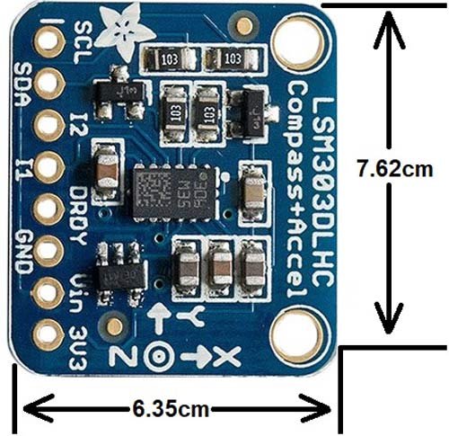
2D Diagram
Related Articles:
- MPU9250 9-DOF MEMS Sensor Module Interfacing with Arduino
- HMC5883L 3-Axis Compass Module Interfacing with Arduino
- MPU6050
| Arduino Components | Amazon Links |
|---|---|
| Arduino Starter Kit | Buy Now |
| Arduino Development Kit | Buy Now |
| Arduino Smart Robot Car Kit V4 | Buy Now |
| Arduino Sensors Kit | Buy Now |