MPU9250 9-DOF Gyro Accelerator Magnetometer Module with Arduino (original) (raw)
In this tutorial, we will learn to interface MPU9250 9-DOF Gyro Accelerator Magnetometer Module with Arduino. Firstly, we will see the introduction of this 9-DOF MEMS sensor module, pinout, and specifications. In the end, we will see an example to measure 3-axis values of Gyro, Accelerator Magnetometer
MPU9250 9-Axis Gyro Accelerator Magnetometer Module Introduction
MPU9250 is a multi-tasking sensor module based on MEMS (Micro Electro Mechanical Systems) architecture. It is a product by Asahi Kasei Microdevices Corporation. The MPU9250 is a 9-axial Motion Tracking device with a 3-Dimensional gyroscope, 3-Dimensional magnetometer, and 3-Dimensional accelerometer embedded into an ultra-compact IC. The high-performance IC has 16-bit resolution analog-to-digital Converters. The sensitive module also has a VDDIO, an inbuilt temperature sensor, and an auxiliary I2C interface data transmission with non-inertial sensors.
The 9-DOF Sensor module comes with an I2C interface with a data rate of 400 kHz. A Serial Peripheral Interface for fast mode with a rate of up to 20 MHz is provided in the module. It also has frame synchronization. The MPU9250 finds its applications in most of the intelligent electronics consumer products in one way or the other. Virtual Reality gaming is the perfect application of MPU9250 9-DOF MEMS Sensor module.

This tutorial will share the pin configuration, features, specification, interfacing, and applications.

MPU9250 Components
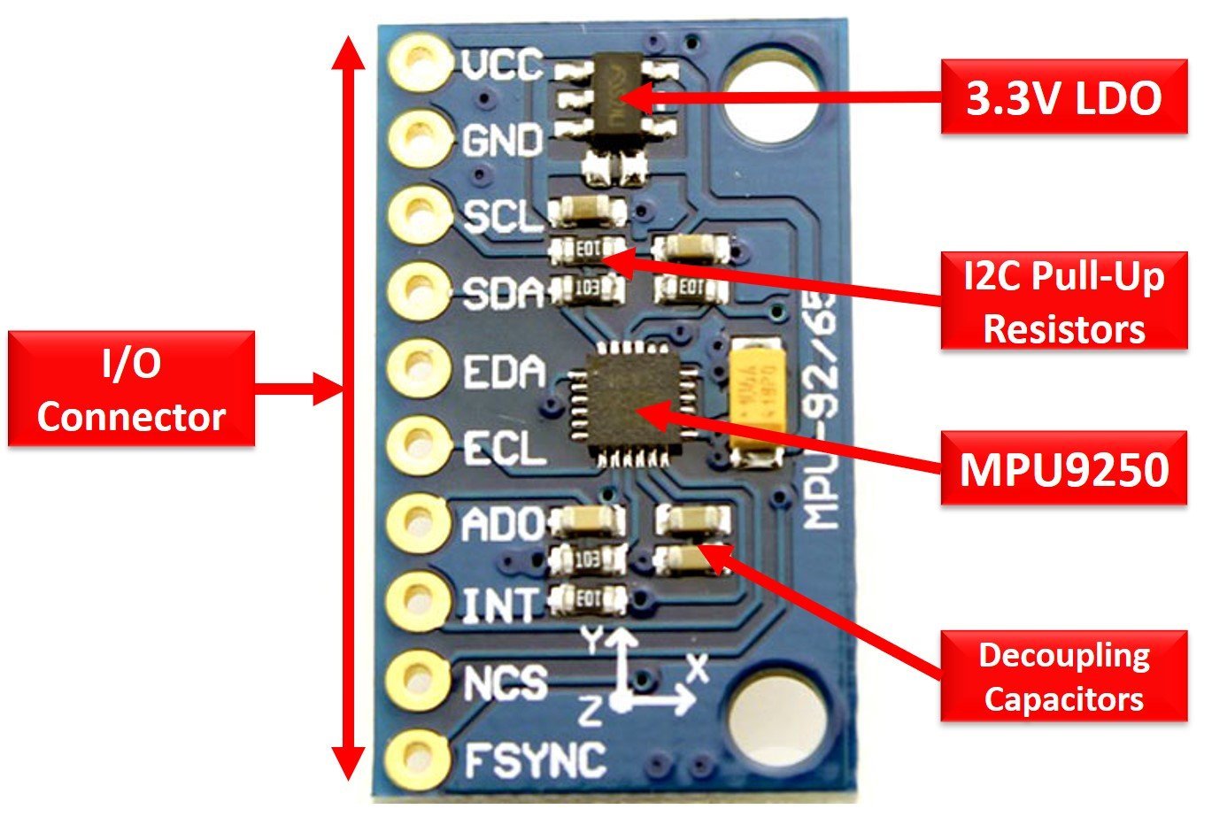
The MEMS Sensor module consists of MPU9250, I/O Headers, Pull-up Resistors, LDO, and Decoupling Capacitors.
MPU9250 chip: The IC is integrated with an accelerometer, gyroscope, and magnetometer and does all the processing.
I/O Headers: The headers will serve the purpose of connectivity and data transmission with the microcontroller unit.
Pull-up Resistors: The pull resistors are placed for I2C Bus to source current and establish a default state.
LDO: LDO voltage regulator is provided to reduce the voltage to 3.3V for the IC functioning and increase power efficiency.
Decoupling Capacitors: The decoupling capacitors remove the unwanted noise from the signals.
Internal Circuit Diagram
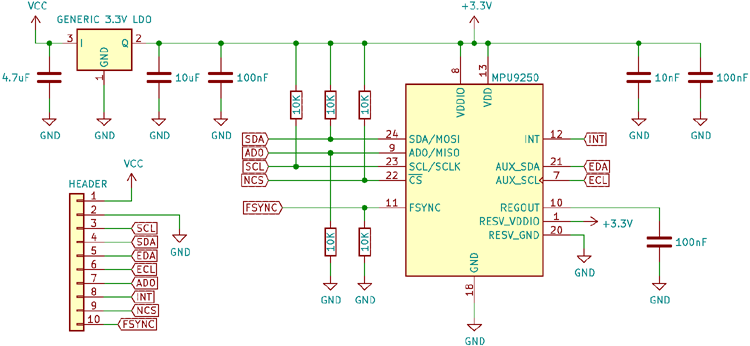
The following diagram shows the pinout of the MPU 9250 9-DOF MEMS Sensor Module:

Pin Configuration
MPU9250 9-DOF MEMS Sensor Module has a total of 10 pins. The pin configuration detail in the tabular is mentioned below:
| Pin Name | Function |
|---|---|
| Pin Name | Function |
| INT | Interrupt pin |
| ECL | I2C Master Serial Clock for external sensors connection pin |
| AD0/SDO | I2C Address/Serial data out pin |
| FSYNC | Frame Synchronization input pin |
| VCC | Power supply pin |
| GND | Ground pin |
| EDA | I2C Serial Data input for external sensors connection pin |
| nCS | Chip selection pin |
| SCL/SCLK | I2C Serial Clock/SPI Serial Clock pin |
| SDA/SDI | I2C Serial Data/SPI Serial Data pin |
MPU9250 Features and Specifications
Following are some of the features of the MPU 9-DOF MEMS Sensor Module:
| Features and Peripherals | Availability |
|---|---|
| Structure | MEMS |
| SPI Data Rate | 1 Mhz |
| SPI Fast Data Reading Rate | 20 Mhz |
| I2C Data Rate | 400 kHz |
| Shock tolerance | 10,000g |
| FIFO buffer | 512 Bytes |
| Auxiliary I2C interface | 1 |
| SPI | 1 |
| I2C | 1 |
| Operating Voltage | 2.4-3.6 Volts |
| Operating Current | 3.5mA |
| VDDIO | Yes |
| Digital Output Temperature Sensor | Yes |
| Cross-Sensitivity | Minimum |
| User-Programmable Digital Filters | Yes |
| Package Type | QFN |
| Dimensions | 3x3x1mm |
Detailed Features
Some of the useful features MPU 9-DOF MEMS Sensor Module are listed below:
- It has a triple-axis MEMS gyroscope, accelerometer, and magnetometer
- Digital-output accelerometer full-scale range: ±2g, ±4g, ±8g, and ±16g
- Digital-output 3-Axis Gyroscope full-scale range:±250, ±500, ±1000, and ±2000°/sec
- Hall-effect Magnetometer full-scale measurement range: ±4800µT
- It comes with triple pair of three 16-bit Analog-to-Digital Converters
- The module has a user-programmable low-pass filter and wake-on-motion interrupt to operate in low power mode
- Gyroscope operating current: 3.2mA
- Accelerometer Operating current: 450µA
- Magnetometer Operating current: 280µA
- Magnetometer Repetition Rate: 8Hz
- Sleep mode operating current: 8µA
- Magnetometer output data resolution: 14-bit (0.6µT/LSB)
- The module has I2C, SPI and an additional Auxiliary I2C interface.
- It is embedded with a Self-test function to diagnose the operations of the module to ensure its proper functioning.
MPU9250 Interfacing with Arduino
This section deals with the interfacing of an Arduino microcontroller to the MPU 9-DOF MEMS Sensor Module. MPU 9-DOF MEMS Sensor Module interfaces with any microcontroller using an I2C bus. In this section, we will see how to use MPU9250 with Arduino.
Almost all Arduino modules support at least one I2C communication port. Therefore, you can use any Arduino module. Now let’s see how to interface Arduino with MPU9250 module.
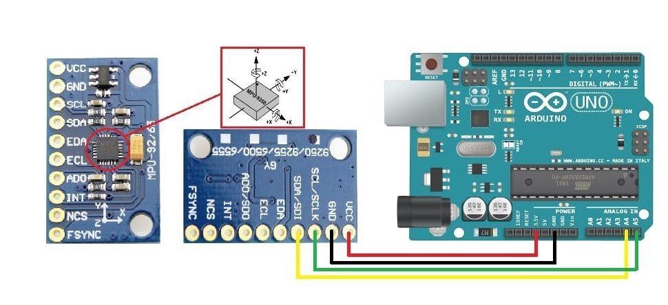
Arduino I2C Pins
The I2C pins stated above are set in default. If we want to change the GPIO pins we have to set them in code. The diagrams below show the I2C pins of Arduino marked with different color rectangles.

Arduino Uno I2C Pins
Note: If we use other GPIO pins of Arduino for I2C communication, we can define other pins inside our Arduino sketch. We don’t have to use default I2C pins.
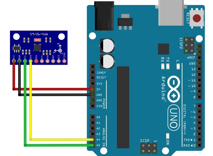
Connection Diagram
For the interface, connect the power supply pins and SDA, and SCL pins of both the components according to the connection diagram shown below:
- Connect the power supply pins of the module to the ground and 5Volts pin of the Arduino.
- Connect the SDA and SCL pins of the Sensor module to any of the analog pins of the Arduino for serial data communication.
- Make sure to use long jumpers to avoid disturbance because we would rotate the module three-dimensionally to observe the result.
| Arduino Uno | MPU9250 |
|---|---|
| 5V | VCC |
| GND | GND |
| SDA | A4 |
| SCL | A5 |
You may also like to read:
MPU9250 Arduino Code
For the MPU9250 code for Arduino, we will use an Arduino library. First, let’s see how to install the MPU9250 library in Arduino IDE.
Install MPU9250 Library
First, download the MPU9250 and install it to the Arduino IDE. Restart the Arduino IDE. It is easy to use the library written specifically for the module. After installation, include the library to sketch the code. Download the zip file of MPU9250 then follow these steps to install the library: Sketch >Include Library> Add .ZIP Library.
To see the example codes follow these steps: File>Examples>MPU9250_Master.
The library has six example codes i.e.
- Advanced_I2C
- Basic_I2C
- FIFO_SPI
- Basic_SPI
- Interrupt_SPI
- WOM_I2C
Example I2C Sketch
#include "MPU9250.h"

// an MPU9250 object with the MPU-9250 sensor on I2C bus 0 with address 0x68
MPU9250 IMU(Wire, 0x68);
int status;

void setup() {
  // serial to display data
  Serial.begin(115200);
  while (!Serial) {}

  // start communication with IMU
  status = IMU.begin();
  if (status < 0) {
    Serial.println("IMU initialization unsuccessful");
    Serial.println("Check IMU wiring or try cycling power");
    Serial.print("Status: ");
    Serial.println(status);
    while (1) {}
  }
}

void loop() {
  // read the sensor
  IMU.readSensor();
  // display the data
  Serial.print(IMU.getAccelX_mss(), 6);
  Serial.print("\t");
  Serial.print(IMU.getAccelY_mss(), 6);
  Serial.print("\t");
  Serial.print(IMU.getAccelZ_mss(), 6);
  Serial.print("\t");
  Serial.print(IMU.getGyroX_rads(), 6);
  Serial.print("\t");
  Serial.print(IMU.getGyroY_rads(), 6);
  Serial.print("\t");
  Serial.print(IMU.getGyroZ_rads(), 6);
  Serial.print("\t");
  Serial.print(IMU.getMagX_uT(), 6);
  Serial.print("\t");
  Serial.print(IMU.getMagY_uT(), 6);
  Serial.print("\t");
  Serial.print(IMU.getMagZ_uT(), 6);
  Serial.print("\t");
  Serial.println(IMU.getTemperature_C(), 6);
  delay(100);
}
Code Explanation
Include Library
To program a code in Arduino, the first is always to add the header files. Include the concerned header file, to interface the MPU9250 9-DOF MEMS Sensor Module to the Arduino. It has already written codes for reading the values of the accelerometer, gyroscope, and magnetometer. Through these inbuilt codes, it will take in, process, and output the acceleration, angle, and magnetic field to determine the position and orientation of the module.
#include "MPU9250.h"IMU Object
An object “IMU” is created with an address i.e. 0x68 on the I2C Bus. It is done with the help of the MPU9250 sensor to store and act on the data and return the respective measurements.
// an MPU9250 object with the MPU-9250 sensor on I2C bus 0 with address 0x68
MPU9250 IMU(Wire, 0x68);
void Setup
The void setup block executes two conditions. First, it initializes the Serial monitor at a baud rate of 11520 bps. If the Serial monitor does not launch and no values are displayed then the execution cycle halts and the code will be stopped. Next a variable “status” is declared that checks the status of the IMU object. If the status is less than 0 i.e no voltage is received then the Serial monitor will display the messages “IMU initialization unsuccessful”, “Check IMU wiring or try cycling power” and then prints the value stored in status. As this is a forever condition because of the while(1) statement , the code will not go further unless the status value is greater than 0.
// serial to display data
  Serial.begin(115200);
  while (!Serial) {}

  // start communication with IMU
  status = IMU.begin();
  if (status < 0) {
    Serial.println("IMU initialization unsuccessful");
    Serial.println("Check IMU wiring or try cycling power");
    Serial.print("Status: ");
    Serial.println(status);
    while (1) {}
  }
void loop
The execution cycle enters the void loop block when the status of IMU is more than 0. The loop will read the IMU through readSensor(). They read the values of the accelerometer, gyroscope, and magnetometer.
The value of acceleration in mG in x-axis, y-axis and z-axis is read through getAccelX_mss(), getAccelY_mss() and getAccelZ_mss() respectively and displayed in Serial monitor. The value will be displayed upto 6 decimal places.
The measurement of angle in radians per second in x-axis, y-axis and z-axis is read through getGyroX_rads(), getGyroY_rads() and getGyroZ_rads() respectively and displayed in Serial monitor. The value will be displayed up to 6 decimal places as well.
Similarly, the value of magnetic field strength in Tesla in x-axis, y-axis and z-axis is read through getMagX_uT(), getMagY_uT() and getMagZ_uT() respectively and displayed in the Serial monitor. The value will also be displayed up to 6 decimal places.
Finally, it will get the value of temperature through getTemperature_C() up to 6 decimal places.
 // read the sensor
  IMU.readSensor();
  // display the data
  Serial.print(IMU.getAccelX_mss(), 6);
  Serial.print("\t");
  Serial.print(IMU.getAccelY_mss(), 6);
  Serial.print("\t");
  Serial.print(IMU.getAccelZ_mss(), 6);
  Serial.print("\t");
  Serial.print(IMU.getGyroX_rads(), 6);
  Serial.print("\t");
  Serial.print(IMU.getGyroY_rads(), 6);
  Serial.print("\t");
  Serial.print(IMU.getGyroZ_rads(), 6);
  Serial.print("\t");
  Serial.print(IMU.getMagX_uT(), 6);
  Serial.print("\t");
  Serial.print(IMU.getMagY_uT(), 6);
  Serial.print("\t");
  Serial.print(IMU.getMagZ_uT(), 6);
  Serial.print("\t");
  Serial.println(IMU.getTemperature_C(), 6);
  delay(100);
Upload the code on the Arduino UNO. The MEMS Sensor module will take up the values. As soon as the Serial monitor is launched, the position and orientation is displayed like
- “AccelX AccelY: AccelZ: ”
- “GyroX: GyroY: GyroZ: ”
- “MagX: MagY: MagZ:”
- “Temperature in C: ”
Rotate the sensor module in three dimensions as you like. The values at that particular time are shown on the Serial monitor. We can interface an LCD or an OLED to present the measurement. The example codes are flexible. They can be used as it or can be calibrated as per the requirement of the user.

Alternate Options
- ADXL335
- MPU6050
Applications
- Joysticks controllers
- Medical Systems
- 3D remote controls
- Set top boxes
- Orientation Detection
- Wearable sensors for health, fitness and sports
- Location based services
- VR Gaming
- Robotics
2D Diagram

Related Articles:
- MPU6050 Sensor Module gyroscope and accelerometer
- MPU6050 Gyroscope Accelerometer sensor interfacing with TM4C123G Tiva C Launchpad
- ESP32 MPU6050 Web Server Accelerometer and Gyroscope Dashboard with 3-D animation (SSE Events)
- MPU6050 with Raspberry Pi Pico (Accelerometer, Gyroscope, and Temperature)
- MPU6050 Sensor Module Interfacing with Pic Microcontroller
- MPU6050 with Arduino – Display values on SSD1306 OLED
- ESP32 with MPU6050 Accelerometer, Gyroscope, and Temperature Sensor ( Arduino IDE)
- ESP8266 MPU6050 Web Server Accelerometer and Gyroscope Dashboard with 3-D animation (SSE Events)
- ESP32 Fall Detection using MPU6050 with Email Alerts
| Arduino Components | Amazon Links |
|---|---|
| Arduino Starter Kit | Buy Now |
| Arduino Development Kit | Buy Now |
| Arduino Smart Robot Car Kit V4 | Buy Now |
| Arduino Sensors Kit | Buy Now |