three phase variable frequency SPWM for VFD using pic microcontroller (original) (raw)
In last article, I have posted a project on three phase sine wave inverter using pic microcontroller. In this article, I will talk about three phase variable frequency SPWM for VFD using pic microcontroller. three phase variable frequency SPWM is used to generate variable frequency for three phase induction motor. This is also used for variable frequency drive for three phase induction motor. In next article, I will post a complete project of three phase variable frequency drive using pic microcontroller. This tutorial is a simulation and demonstration of three phase variable frequency SPWM using pic microcontroller. So now lets start with basic introduction of this project. you may also like to check other power electronics projects.
In this project, PIC18F452 microcontroller is used to generate variable sinusoidal pulse width modulation signals. Variable frequency sinusoidal pulse width modulation signals are 120 degree out of phase with each other. Because, you know in case of three phase power, all three phases must be 120 out of phase with each other. For generation of SPWM signals, I have used a look up table with pre calculated values of duty cycle for pulse width modulation. These pre-calculated duty cycle values are used to generate sinusoidal pulse width modulation. Because value of duty cycle increases from low value to high value. Maximum duty cycle will be at the peak of sine wave and minimum duty cycle will be at the zero crossing. If you don’t know how to generate SPWM, you can check this article:
- SPWM generation using pic16f877a microcontroller
- SPWM generation using Dspic microcontroller
- SVPWM using pic microcontroller
Variable resistor is used to increase or decrease the frequency of SPWM signals. Variable resistor is connected with analog channel of pic18f452 microcontroller. Six signals coming out of pic microcontroller will be fed to three phase H bridge to get three phase sine wave with variable frequency. you can check our article on how to design H bridge using MOSFET driver IR2110.

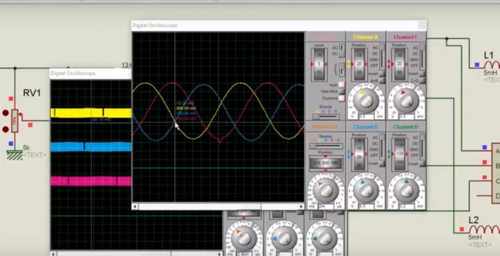
- Picture below shows three SPWM signals and all three are 120 degree out of phase with each other.

- Output with filters pure sine wave

you can check this complete simulation to check more working of this three phase variable frequency SPWM for VFD using pic microcontroller.
[button-brown url=”http://microcontrollerslab.com/contact-us/” target=”_blank” position=”center”]Contact us to purchase code[/button-brown]