Dobsonian Mirror Edge Support Calculator (original) (raw)
Welcome to the Mirror Edge Support Calculator. This tool can help you to choose or validate the lateral support of your telescope mirror - the part of the mirror cell that supports the mirror when it's pointing to the horizon.
Just plug in the dimensions of your telescope mirror, select a support configuration, and compute the mirror surface deformation. Read further below for a discussion of the best support configurations and the acceptable level of error.
Discussion
Approach to Mirror Cell Design
To design a mirror cell that will make your mirror perform at its very best, follow this procedure:
- Use the program PLOP to optimize the back support for the mirror pointing to the zenith.
- Use this Mirror Edge Support Calculator to analyze the edge support for the mirror pointing to the horizon.
Obtaining an outstanding mirror cell design has never been this easy!
Selection of the edge support configurations
Amateur telescope makers have historically focused most on the back support, but with the evolution towards ever larger and thinner mirrors the edge support issue has become increasingly important.
The edge support configurations have been selected after extensive discussions and represent the state-of-the-art ideas about the edge support in mirror cells for Dobsonian telescopes from a number of experts including Mauro Da Lio, Nils Olof Carlin and Dale Eason.
A short summary:
- 180° cable sling: theoretically the best edge support, but quite sensitive to positioning errors and out-of-plane forces. To approach the theoretical performance the cable should be positioned as perfectly as possible in the plane of the center of gravity (COG) of the mirror.
- 90° edge bearings: two edge posts (roller bearings or piano wire supports) separated by 90° at the level of the COG of the mirror. Theoretically slightly less good than the cable sling, but this is compensated by the simple and very robust mechanical design that makes it easy to avoid out-of-plane forces and keep the support precisely at the COG. It is not wise to deviate from the 90° separation as considerable astigmatism will occur at other angles.
- 45° whiffletree support: four edge support points separated by 45° (22.5° and 67.5° from the vertical). Yields better computational results than the simple 90° bearings, but at the cost of increased complexity and practical difficulty of keeping the 4 supports points at the COG of the mirror.
For most mirrors the 90° edge bearings should give the most robust and simple implementation.
For large, thin mirrors it is vital to put the edge support as precisely as possible at the COG of the mirror. Even small deviations of the order of 0.1 inch or 2.5 mm could lead to visible astigmatism. You can evaluate the impact of not precisely putting the edge support at the COG by means of the configurations with 1/20th mirror thickness offset. This corresponds to a 0.1"/2.5 mm offset on a 2 inch (50 mm) thick mirror.
In all cases a very stiff edge support is required to prevent the mirror from sliding down on the support pads when the telescope goes from zenith to horizon. If the mirror slides, the friction between mirror back and support pads could create astigmatism.
Some other configurations are included:
- mirror glued on 18-point cell: only suitable for smaller mirrors. See discussion below.
- 120° edge bearings: this configuration is often encountered in smaller commercial telescopes. The surface errors typically are 2 to 5 times larger than for the 90° edge support, and it should be avoided on large, thin mirrors.
Some links to web sites that contain well constructed edge supports
- Jan Van Gastel's pages contain a lot of useful construction information about mirror cells, cable slings, 90° edge bearings - both the piano wire and roller bearing types - for a 20 inch telescope.
- Nils Olof Carlin's three-part sling is an interesting cable sling implementation that solves the problem of side movement of the mirror
- A simple cable sling implementation for a 16 inch mirror.
- An elegant 45° whiffletree support for a 600 mm (24 inch) mirror.
What level of RMS Surface Error is acceptable?
The computed RMS Surface Error is given in nm (nanometer). The traditional "diffraction-limited" mirror corresponds to an RMS surface error of 20 nm (1/27 wave). The mirror cell should generate errors that are significantly below this value; a value of 5 nm or belowcorresponds to a virtually perfect edge support.
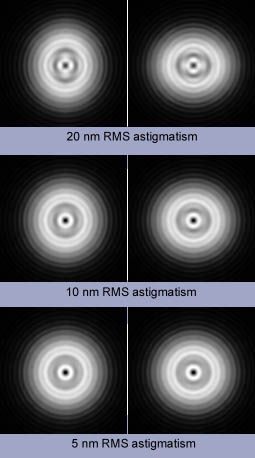
To the right are some highly magnified star-test simulations for different levels of astigmatism, generated with Aberrator at out-of-focus positions of 2 waves.
- For a 20 nm RMS surface error (corresponding to 3/8 wave of astigmatism in Aberrator) the star image is clearly astigmatic: the diffraction pattern is egg-shaped and oriented differently in and out of focus.
- At the 10 nm RMS level an experienced observer would just be able to spot the astigmatism.
- The 5 nm RMS level is indistinguishable from perfection.
Another way of looking at the error is by means of the Strehl Ratio of the optical system (a number between 0 and 1, 1 being a perfect mirror). Very often mirror makers will communicate this value for the mirrors they produce. The computed reduction of the Strehl Ratio gives a direct way of expressing the degradation of the image quality by the mirror cell.
The calculator will show the Strehl Ratio reduction at 45° height and at the horizon. If you have a fine quality primary mirror with a Strehl ratio of 0.97 you probably don't want the mirror cell to reduce it by more than 0.01 at 45° height.
Are these errors only relevant when I observe at the horizon?
Arguably few people will ever observe with the telescope pointing at the horizon, but the computed errors do not only apply to the case where the telescope is pointing at the horizon. At 30° altitude the load on the edge support will be about 87% of the weight, so you will still have about 87% of the computed error. At 45° altitude this drops to 71%, and at 60° altitude you still have 50% of the computed error.
Why should I not use other configurations - for example edge bearings at 30° from the vertical?
Many edge support configurations are possible, but just a few will give surface deformations without astigmatism. To illustrate this, a number of different configurations have been computed for a 600x50 mm (24"x2") f/3.3 mirror. For each configuration the RMS surface error is shown with the support at the COG, and at 2.5 mm above the COG.
| Configuration | Description | RMSat COG | RMS 2.5 mmabove COG |
|---|---|---|---|
| 180° cable sling | cable on half the mirror circonference | 1.8 nm | 6.6 nm |
| 120° cable sling | cable on a third of the mirror circonference | 7.6 nm | 12.0 nm |
| 90° cable sling | cable on a quarter of the mirror circonference | 10.7 nm | 18.5 nm |
| 90° edge bearings | 2 support points at 45° from vertical | 4.0 nm | 10.7 nm |
| 60° edge bearings | 2 support points at 30° from vertical | 8.9 nm | 14.6 nm |
| 120° edge bearings | 2 support points at 60° from vertical | 16.7 nm | 39.7 nm |
| mirror on edge | one support point at bottom of mirror | 15.6 nm | 28.6 nm |
| 45° whiffletree | 4 support points at 22.5° and 67.5° from vertical | 2.0 nm | 7.0 nm |
| 30°/60° whiffletree | 4 support points at 30° and 60° from vertical | 2.8 nm | 8.4 nm |
| 30° whiffletree | 4 support points at 15° and 45° from vertical | 8.0 nm | 12.8 nm |
| 14°/45° whiffletree | 4 support points at 14° and 45° with unequal load (Alois Ortner) | 7.1 nm | 10.5 nm |
The 180° cable sling, the 90° edge bearings and the 45° whiffletree at the COG are optimal as they produce situations in which the astigmatism in the surface deformation disappears.
What is the basis for these results and how accurate are they?
The results have been computed using full three-dimensional Finite Element models of parabolic mirrors. The mirror models have been generated by MirrorMesh3D and contain on the average about 70,000 elements. The surface errors have been computed after removing tilt and focus from the surface deformations.
For each support configuration about 50 analyses were required to cover the range of focal ratio (3 to 10) and relative mirror thickness (1:6 to 1:25) typically found in amateur telescopes.
The accuracy level is probably between 10% and 25%. You can compare some results with those found by Mauro Da Lio using a completely different mirror model and finite element package. The method has also been validated by comparison with Plop for some mirror configurations on 6, 18 and 27-point cells. See the page on MirrorMesh3D for more details.
Comparison with test results
The analyses are made for ideal cases with the following boundary conditions:
- Exact vertical positioning of the edge support (usually at the level of the center of gravity)
- Exact angular positioning of the edge support (at 45° or 22.5°/67.5° from vertical)
- No out-of-plane forces arising from friction or out-of-plane sling
- No friction between the mirror and the back support
It's difficult to find accurate interferometer test data in which these conditions are carefully respected. Very often even professional mirror makers with interferometer equipment are not aware of the importance of supporting the mirror properly at the COG during the test. It is a general practice in mirror testing to remove "test stand astigmatism" without worrying too much about whether the astigmatism could have been eliminated by implementing an adequate edge support.
When comparing results remember that tests usually measure wavefront errors that are twice as large as the surface errors, and make sure to compare the RMS error value and not P-V (Peak-to-Valley) results.
My mirror is not made of Pyrex
The FE analyses are made for Pyrex mirrors with a density of 2230 kg/m³, Young's modulus of 62.8 GPa and Poisson ratio of 0.2. For other materials, you can correct the results by applying the appropriate ratio of the density and the Young's modulus.
For plate glass with density of 2520 kg/m³ and Young's modulus 72 GPa the results can be used without correction.
For fused silica or quartz with density 2200 kg/m³ and Young's modulus 72 GPa, you should multiply the RMS errors by 2200/2230 * 62.8/72 = 0.86.
These multipliers fall within the "10 to 25%" accuracy level of the analyses and will probably not influence your choice of edge support configuration.
How about gluing the back of the mirror instead of using an edge support?
A mirror glued on the mirror cell (in the analysis an 18-point cell has been chosen) is a rather extreme case of offsetting the lateral support from the COG of the mirror. It is important to make sure that the vertical load will be distributed evenly over all support points.
The FE analyses suggest that for the configurations found in amateur telescopes, gluing will only work well for relatively small, thick mirrors; the upper diameter limit for a standard thickness mirrors appears to lie around 15" diameter. Use the "glued mirror configuration" to verify your particular case.
Glued mirrors work in much larger professional telescopes, isn't that contradictory?
On professional telescopes more sophisticated devices are used than simply gluing the mirror on a whiffletree support cell. One usually finds a push-pull mechanism on the back that compensates for the moment due to the eccentricity of the lateral force with respect to the center of the gravity. This push-pull mechanism makes all the difference: it assures that the bending moment is absorbed locally and not globally (which causes astigmatism). So gluing can work on large, thin mirrors, if you can control the moment distribution very precisely and make sure that bending moments have no global effect. This is not the case in most amateur telescopes.
Version history
- Version 1.0 (20071126)
- Version 1.1 (20071128) Glued mirror case and Strehl reduction calculation added
- Version 1.2 (20071201) 1/20th mirror thickness offset cases added
- Version 1.3 (20080109) Useful links to construction examples
- Version 1.4 (20080307) Show sagitta and estimated mirror weight
- Version 1.5 (20080707) Aberrator simulations of surface errors + 120° edge bearings configuration added