Electrostatics of nanosystems: Application to microtubules and the ribosome (original) (raw)
Abstract
Evaluation of the electrostatic properties of biomolecules has become a standard practice in molecular biophysics. Foremost among the models used to elucidate the electrostatic potential is the Poisson-Boltzmann equation; however, existing methods for solving this equation have limited the scope of accurate electrostatic calculations to relatively small biomolecular systems. Here we present the application of numerical methods to enable the trivially parallel solution of the Poisson-Boltzmann equation for supramolecular structures that are orders of magnitude larger in size. As a demonstration of this methodology, electrostatic potentials have been calculated for large microtubule and ribosome structures. The results point to the likely role of electrostatics in a variety of activities of these structures.
The importance of electrostatic modeling to biophysics is well established; electrostatics have been shown to influence various aspects of nearly all biochemical reactions. Advances in NMR, x-ray, and cryo-electron microscopy techniques for structure elucidation have drastically increased the size and number of biomolecules and molecular complexes for which coordinates are available. However, although the biophysical community continues to examine macromolecular systems of increasing scale, the computational evaluation of electrostatic properties for these systems is limited by methodology that can handle only relatively small systems, typically consisting of fewer than 50,000 atoms. Despite these limitations, such computational methods have been immensely useful in analyses of the stability, dynamics, and association of proteins, nucleic acids, and their ligands (1–3). Here we describe algorithms that open the way to similar analyses of much larger subcellular structures.
One of the most widespread models for the evaluation of electrostatic properties is the Poisson-Boltzmann equation (PBE) (4, 5)
 |
1 |
|---|
a second-order nonlinear elliptic partial differential equation that relates the electrostatic potential (φ) to the dielectric properties of the solute and solvent (ɛ), the ionic strength of the solution and the accessibility of ions to the solute interior (κ̄2), and the distribution of solute atomic partial charges (f). To expedite solution of the equation, this nonlinear PBE is often approximated by the linearized PBE (LPBE) by assuming _sinh_φ(x) ≈ φ(x). Several numerical techniques have been used to solve the nonlinear PBE and LPBE, including boundary element (6–8), finite element (9–11), and finite difference (12–14) algorithms. However, despite the variety of solution methods, none of these techniques has been satisfactorily applied to large molecular structures at the scales currently accessible to modern biophysical methods. To accommodate arbitrarily large biomolecules, algorithms for solving the PBE must be both efficient and amenable to implementation on a parallel platform in a scalable fashion, requirements that current methods have been unable to satisfy. Although boundary element LPBE solvers provide an efficient representation of the problem domain, they are not useful for the nonlinear problem and have not been applied to the PBE on parallel platforms. Similarly, adaptive finite element methods have shown some success in parallel evaluation of both the LPBE and nonlinear PBE (15), but limitations in current solver technology and difficulty with efficient representation of the biomolecular data prohibits their practical application to large biomolecular systems. Finally, unlike the boundary and finite element techniques, finite difference methods have the advantage of very efficient multilevel solvers (12, 16) and applicability to both the linear and nonlinear forms of the PBE; however, existing parallel finite difference algorithms often require costly interprocessor communication that limits both the nature and scale of their execution on parallel platforms (17–21) [see especially Van de Velde (19) for reviews of the various methods].
Multigrid Solution Through Parallel Focusing
Recently, a new algorithm (Bank-Holst) was described for the parallel adaptive finite element solution of elliptic partial differential equations with negligible interprocess communication (22). Unlike finite difference methods, which use a fixed resolution of the problem domain, adaptive finite element techniques generate very accurate solutions of these equations by locally enriching the basis set in regions of high error through refinement of the domain discretization. The first step in the Bank-Holst parallel finite element algorithm is the solution of the equation over the entire problem domain using a coarse resolution basis set by each processor. This solution is then used, in conjunction with an a posteriori error estimator, to partition the problem domain into P subdomains, which are assigned to the P processors of a parallel computer. The algorithm is load balanced by equidistributing a posteriori error estimates across the subdomains. Each processor then solves the partial differential equation over the global mesh, but confines its adaptive refinement to the local subdomain and a small surrounding overlap region. This procedure results in a very accurate representation of the solution over the local subdomain. After all processors have completed their local adaptive solution of the equation, a global solution is constructed by the piecewise assembly of the solutions in each subdomain. It can be rigorously shown that the piecewise-assembled solution is as accurate as the solution to the problem on a single global mesh (23). Because each processor performs all of its computational work independently, the Bank-Holst algorithm requires very little interprocess communication and exhibits excellent parallel scaling. Unfortunately, although this algorithm works well for adaptive techniques, such as finite elements, it is not directly applicable to the fixed-resolution finite difference methods that currently offer the most efficient solution of the PBE for large molecular systems. However, by combining the Bank-Holst method with other techniques, we have been able to extend this algorithm to finite difference solvers.
Electrostatic “focusing” is a popular technique in finite difference methods for generating accurate solutions to the PBE in subsets of the problem domain, such as a binding or titratable sites within a protein (4, 14). Like the Bank-Holst method, the first step in electrostatic focusing is the calculation of a low-accuracy solution on a coarse finite difference mesh spanning the entire problem domain. This coarse solution is then used to define the boundary conditions for a much more accurate calculation on a finer discretization of the desired subdomain. As noted previously (22), this focusing technique is superficially related to the Bank-Holst algorithm, where the local enrichment of a coarse, global solution has been replaced by a the solution of a fine, local multigrid problem using the solution from a coarse, global problem for boundary conditions.
We have combined standard focusing techniques and the Bank-Holst algorithm into a “parallel focusing” method for the solution of the PBE. Unlike previous parallel algorithms for solving the PBE, this method has excellent parallel complexity, permitting the treatment of very large biomolecular systems on massively parallel computational platforms. Furthermore, the finite difference discretization on a regular mesh allows for fast solution by certain highly efficient multigrid solvers (12). The algorithm is summarized below:
Given the problem data and P processors of a parallel machine:
(i) Each processor i = 1...,P (a) obtains a coarse solution of the PBE over the global domain, (b) heuristically subdivides the global domain into P subdomains (Ω1...,ΩP), which are assigned to processors 1...,P, (c) assigns boundary conditions to its subdomain Ωi using the coarse global solution, and (d) solves the PBE on subdomain Ωi.
(ii) A master processor collects observable data (free energy, etc.) from the other processors and controls I/O.
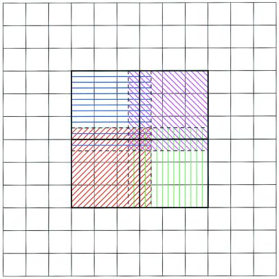
This parallel focusing algorithm begins with each processor independently solving a coarse global problem. The per-processor subdomains are chosen in a heuristic fashion as outlined in Fig. 1. Like standard focusing calculations, only a subset of the global mesh surrounding the area of interest is used for the parallel calculations. This subset is partitioned into P approximately equal subdomains, which are distributed among the processors. Each processor then performs a fine-scale finite difference calculation over this subdomain and an overlap region that usually spans about 5–10% of the neighboring subdomains. The overlap regions are included to compensate for inaccuracies in the boundary conditions derived from the global coarse solution; however, these regions are not used to assemble the fine-scale global solution and do not contribute to calculations of observables such as forces and energies. After the fine-scale calculations are complete, a master processor accumulates the desired data from the other processes and controls I/O of the solution. Like the Bank-Holst algorithm, each process computes independently on both the global coarse problem and its subdomain. These independent computations result in an algorithm that requires negligible interprocess communication and offers excellent parallel performance.
Figure 1.
Parallel focusing subdomains for four processors on simple two-dimensional mesh. Parallel computations occur on subset (hashed areas) of global mesh. Each processor performs calculations over a domain (colored hashed patterns) that combines a unique partition (inside heavy, black lines) with an overlap region (between heavy black lines and dashed lines).
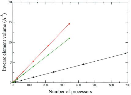
Because of its low communication requirements, this parallel focusing algorithm can be used on parallel platforms ranging from low-bandwidth networks of workstations to high-performance supercomputers. Because step d of the parallel focusing algorithm typically dominates the overall computation, this algorithm provides excellent time complexity with respect to the number of processors. Most importantly for Poisson-Boltzmann calculations on large molecules, the mesh resolution increases linearly with the number of processors.** This linear behavior has been observed on calculations involving hundreds of processors; Fig. 2 shows the scaling results for calculations on the biomolecular systems discussed below. The parallel focusing algorithm was tested on up to 700 processors and shows linear scaling over the entire range. The implications of the improved performance available through this parallel algorithm are discussed in more detail in the next section.
Figure 2.
Scaling of the parallel focusing algorithm to solve the LPBE for the microtubule (black line), 50S ribosome subunit (green line), and 30S ribosome subunit (red line) systems on the NPACI IBM Blue Horizon supercomputer. As discussed in the text, the inverse element volume (a measure of the mesh resolution) is a linear function of the number of processors, v(P)−1 = (_h_x_h_y_h_z)−1 = cP, where c = 0.011, 0.043, and 0.032 Å−3/processor for the microtubule, 30S, and 50S systems, respectively.
Parallel focusing has been implemented as an extension (23) of the apbs (Adaptive Poisson-Boltzmann Solver) software package (9) by using the pmg multigrid library to assemble and solve the PBE algebraic systems (12, 16). The parallel routines have been implemented by using maloc, a portable hardware abstraction layer library (23), which allows interprocess communication through a variety of methods.
The following sections describe the application of the parallel focusing techniques to very large biomolecular systems whose electrostatic properties were unattainable by using traditional methods for solving the PBE. Specifically, we examine two important cellular components: a million-atom microtubule fragment and the large and small subunits of the ribosome.
Electrostatic Properties of Microtubules
Within every eukaryotic cell is a complex system of proteins and filaments called the cytoskeleton. The largest structures within the cytoskeleton are microtubules, cylindrical polymers formed from the protein tubulin. Microtubules perform many functions within the cell, from providing basic structure to cell division and transport, and many of these roles involve electrostatic interactions. The recent solution of the structure of tubulin (24) has allowed us to construct a working model of a microtubule containing 90 tubulin dimers. This structure contains more than 1.25 million atoms [the negatively charged C termini of both the α and β subunits were not resolved in the tubulin structure (24) and have not been rebuilt in our microtubule structure], and the structure has dimensions of ≈300 Å × 300 Å × 600 Å. The LPBE was solved at 0.54-Å mesh spacing by using 686 processors of the National Partnership for Advanced Computational Infrastructure (NPACI) Blue Horizon supercomputer. Blue Horizon is a massively parallel IBM RS6000 supercomputer consisting of 1,152 375-MHz Power3 processors distributed among 144 eight-way symmetric multiprocessing nodes. These nodes are connected with the IBM Colony switch, which delivers 350 MB/sec peak message-passing interface performance with 17-ms latency. Following the parallel focusing algorithm, each processor solved the LPBE on a coarse 973 global mesh, as well as a finer 973 spanning a subset of the overall domain. The global solution was obtained in less than 1 h. This system provides an excellent example of the improved performance available through the parallel focusing method. A sequential PBE solver treating the same system at a similar resolution would discretize the problem on a 1,111 × 555 × 555 mesh, requiring more than 350 times more memory and time to solve.
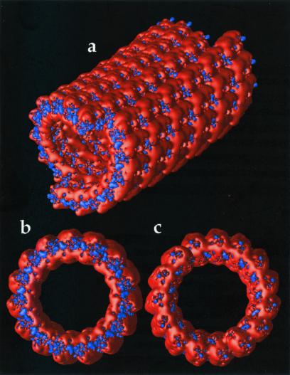
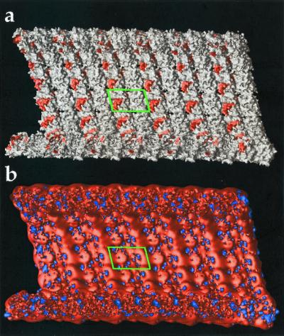
Although more work is presently underway to elucidate the implications of electrostatics on microtubule structure and function, Fig. 3 shows some early results. The most obvious feature is the overall negative electrostatic potential of the microtubule with smaller regions of positive potential. This large negative potential likely plays a significant role in the interaction with microtubule-associated proteins, motor proteins such as kinesin and dynein, and other microtubules. Fig. 3 b and c also exhibits dramatic differences between the + end (β tubulin monomer exposed) and − end (α tubulin monomer exposed) of the microtubule, which, as has been shown for actin filaments (3), may contribute to differences in the polymerization properties (25) and relative stabilities of the two ends. Fig. 4 shows a microtubule inner surface in cross-section. The binding regions of compounds such as vinblastine, colchicine, and taxol (26) are shown in Fig. 4a, while electrostatic isocontours are shown, for the same view, in Fig. 4b. Qualitative examination of the electrostatic data shows interesting variations in the drug binding regions; however, much more work needs to be done to quantitatively elucidate contribution of electrostatics to the interaction of these pharmaceuticals with microtubules.
Figure 3.
Electrostatic properties of the microtubule exterior. Potential isocontours are shown at +1 kT/e (blue) and −1 kT/e (red) and obtained by solution of the LPBE at 150 mM ionic strength with a solute dielectric of 2 and a solvent dielectric of 78.5. (a) Exterior view of entire microtubule with − end (α tubulin monomer exposed) forward. (b) View of − end. (c) View of + end of microtubule (β tubulin monomer exposed).
Figure 4.
Electrostatic properties of microtubule interior. Cross-section view with − end to the left and tubulin dimer outlined by green box. (a) View of microtubule molecular surface with regions implicated in vinblastine, colchicine, and taxol binding shown in red. (b) Same view of microtubule with electrostatic potential isocontours at +1 kT/e (blue) and −1 kT/e (red). Potential calculated as in Fig. 3.
The microtubule also provides a good example for examining the improved performance of this parallel algorithm with respect to sequential solvers.
Electrostatic Properties of the Ribosome
Ribosomes are macromolecular complexes responsible for the translation of the mRNA into protein. These complexes consist of two subunits: the large 50S subunit and the small 30S subunit, both of which are composed of RNA and protein constituents. During translation, the large and small subunits associate to form an active ribosome. Recently, high-resolution structures of the 50S subunit from Haloarcula marismortui (27) and the 30S subunit from Thermus thermophilus (28, 29) were solved by x-ray crystallography. These structures present a unique opportunity to examine the electrostatic potential of large ribonucleoprotein complexes.
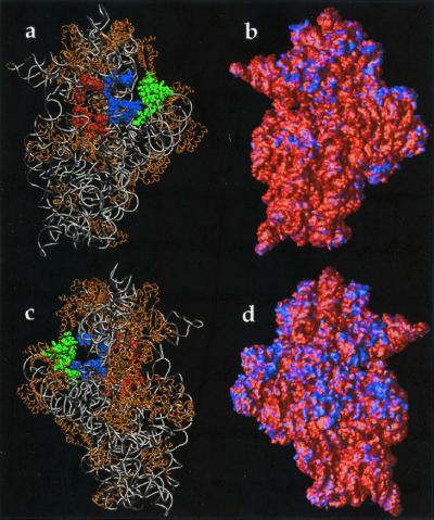
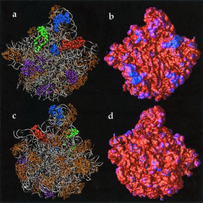
The protonated 30S structure consists of more than 88,000 atoms and roughly spans a 200-Å-long cubic box. Using apbs on 343 processors of the NPACI Blue Horizon, LPBE was solved to give the electrostatic potential of the small ribosomal subunit at 0.41-Å resolution. Calculations also were performed on the protonated 50S subunit structure, which consisted of 94,854 atoms‡‡ and has similar dimensions to the 30S subunit. The electrostatic potential of the large subunit was obtained at 0.45-Å resolution by using apbs to solve the LPBE on 343 processors of the Blue Horizon. Both systems were solved by using the parallel focusing algorithm: each processor first solved a coarse problem defined by a 973 mesh covering the entire problem domain, and the solved the LPBE on a 973 mesh covering the particular subset of the global problem. Examination of the electrostatic potential mapped to the molecular surfaces of the 30S (Fig. 5) and 50S (Fig. 6) reveals large areas of negative potential with smaller regions of positive potential corresponding to some of the proteins implicated in binding of the 30S and 50S subunits to form the active ribosomal complex (27, 29–31). Not surprisingly, the potential surface maps between the two subunits exhibit qualitative electrostatic complementarity. Despite the fact that the 30S and 50S structures are from distinct species that thrive in very different environments, such comparisons of electrostatic potential are not unwarranted. Formation of active ribosomal complexes has been observed by using subunits from different species (32, 33), indicating some evolutionary conservation of the elements involved in subunit association.
Figure 5.
Electrostatic properties of the 30S ribosomal subunit. Potential obtained by solution of the LPBE at 150 mM ionic strength with a solute dielectric of 2 and a solvent dielectric of 78.5 by using the 30S structure from the 1FJG Protein Data Bank entry (29, 34). (a) Front view (face that contacts the 50S subunit) of the 30S backbone with protein shown in gold; nucleic acids shown in silver. Selected components of the A-site (16S residues 525–535, 955–965, 1055–1060, 1490–1493; S12 residues 45–49) are shown in red, components of the P-site (16S residues 789–791, 925–927, 965–967, 1229–1230, 1338–1341, 1399–1403, 1497–1499; S9 residues 124–128; S13 residues 122–126) are shown in blue, and components of the E-site (16S residues 691–695, 792–797; S7 residues 80–90, 150–170; S11 residues 45–60) are shown in green. (b) Front view of the electrostatic potential mapped on the 30S molecular surface; a blue color indicates regions of positive potential (> +2.6 kT/e) whereas red depicts negative potential (< −2.6 kT/e) values. (c) Back view (opposite the 50S-binding face) of the 30S backbone. (d) Back view of the electrostatic potential mapped on the 30S molecular surface.
Figure 6.
Electrostatic properties of the 50S ribosomal subunit. Potential obtained by solution of the LPBE at 150 mM ionic strength with a solute dielectric of 2 and a solvent dielectric of 78.5 by using the 50S structure from the 1FFK Protein Data Bank entry (27). (a) Front view (face that contacts the 30S subunit) of the 50S backbone with protein component (L10e) of the A-site shown as green tube, protein component (L5) of the P-site shown as gold tube, nucleic P-loop portion of P-site shown as gold spheres, protein component (L44e) of E-site shown as white tube, various protein components (L2, L14, L19) of 50S-30S interface shown in purple. Remaining protein components are shown in gold and nucleic acid components in silver. (b) Front view of the electrostatic potential mapped on the 50S molecular surface; a blue color indicates regions of positive potential (>0 kT/e) whereas red depicts negative potential values (< −9.6 kT/e). (c) Back view (opposite the 30S-binding face) of the 50S backbone. (d) Back view of the electrostatic potential mapped on the 50S molecular surface.
Fig. 5 b and d shows the electrostatic potential mapped to the 30S subunit molecular surface. As evidenced by the 30S structure (Fig. 5 a and c), regions of positive potential typically correspond to protein components of the small subunit or cocrystallized counterions. Of particular interest is the active site of the 30S subunit, shown in Fig. 5 a and b. There are interesting variations in the electrostatic potential near regions of antibiotic binding (34) and the A, P, and E tRNA binding sites (29, 34). For example, the codon binding sites and “platform region” (protuberance on the right side of Fig. 5 a and b) are surrounded by regions of positive potential, which could help stabilize complexes of the ribosome with mRNA and tRNA. However, more quantitative calculations will be needed to fully explore these hypotheses.
The electrostatic potential of the 50S subunit is shown in Fig. 6 b and d. Like the small subunit, the electrostatic surface potential is largely negative, with scattered regions of positive potential typically associated with ribosomal proteins. Some of the most interesting aspects of this data set are the regions of positive potential on the 50S “crown” (see upper protuberance in Fig. 6 a and b), which correspond to proteins of the large subunit involved in tRNA binding. Specifically, these positive regions are due to proteins L44e, L5, and L10e (see Fig. 6a), which have been implicated in tRNA binding to the 50S subunit (35), and contribute large regions of positive potential to the molecular surface in the upper portions of the A, P, and E tRNA binding sites. Furthermore, the P-loop (shown as blue spheres in Fig. 6a), an important component of the 50S P-site (35, 36), shows significant positive surface potential due to a nearby Mg2+ ion. These areas of positive potential may provide stabilizing interactions with mRNA or tRNA bound to the ribosomal complex during translation. However, as with the 30S calculations, more detailed work is required to accurately resolve the role of electrostatics in tRNA and mRNA binding to the 50S subunit.
Conclusions
We have described the combination of standard finite difference focusing techniques and the Bank-Holst algorithm into a parallel focusing method to facilitate the solution of the PBE for nanoscale systems. Unlike previous multiprocessor algorithms for solving the PBE, this method has excellent parallel complexity that permits the solution of these problems on massively parallel computational platforms. Furthermore, the finite difference discretization on a regular mesh allows for fast solution by highly efficient multigrid solvers. This algorithm has been implemented in the apbs software by using the pmg multigrid solver and tested on the NPACI IBM Blue Horizon supercomputer.
Using these methods for the parallel multigrid solution of elliptic differential equations, the electrostatic properties of very large biomolecular assemblages are now amenable to computation. This technique relies on the efficient solution of the PBE combined with parallel focusing techniques to solve these large problems in a variety of distributed computational environments. Solution of the LPBE for the 1.2 million-atom microtubule system provided electrostatic potential data, which revealed interesting features near drug binding sites and provided possible insight into stability differences at the + and − ends of the microtubule. Such detailed electrostatic information will be central to future studies that examine the possible collective effects involved in the formation of structural defects and the stabilizing effects of taxol binding to the interior of microtubules. Likewise, application of this methodology to ribosome systems elucidated intriguing electrostatic properties of the ribosomal active site, which will provide the starting point for investigation of the stabilization of the tRNA- and mRNA-ribosome complexes during translation and the rational design of novel antibiotics. Finally, the ability to determine the contribution of electrostatics to the forces and energies of nanoscale systems should extend the scale of implicit solvent dynamics methods to much larger macromolecular complexes.
Acknowledgments
N.A.B. thanks A. Elcock and C. Wong for helpful discussions on the PBE and A. Majumdar and G. Chukkapalli for assistance with technical issues on the Blue Horizon supercomputer. N.A.B. was supported by predoctoral fellowships from the Howard Hughes Medical Institute and the Burroughs-Wellcome La Jolla Interfaces in Science program. This work was supported, in part, by an IBM/American Chemical Society award to N.A.B., providing time on the Minnesota Supercomputing Institute IBM SP2; by grants to J.A.M. from the National Institutes of Health, National Science Foundation, and NPACI/San Diego Supercompter Center; by National Science Foundation CAREER Award 9875856 to M.J.H.; and by National Science Foundation Grant MCB-0078322 to S.J. Additional support has been provided by the W. M. Keck Foundation and the National Biomedical Computation Resource.
Abbreviations
PBE
Poisson-Boltzmann equation
LPBE
linearized PBE
NPACI
National Partnership for Advanced Computational Infrastructure
Footnotes
**
For example, let v(P) = _h_x(P)_h_y(P)_h_z(P) be the volume of a grid element in a P_-processor calculation with 100_f% overlap on a _n_x × _n_y × _n_z mesh with spacings _h_x(P),h_y(P),h_z(P) over a problem domain of volume V. One measure of the mesh resolution is the inverse element volume, which behaves as v(P)−1 ∼(1 − 2_f)3_P(n x − 1)(n y − 1)(n _x_− 1)/V, which is linear in P.
‡‡
The 50S Protein Data Bank coordinate file (1FFK) (27) contained only Cα coordinates for the protein constituents. Therefore, each protein residue was simply represented by its Cα atom, which was assigned the total charge of the residue and a radius of 4.0 Å.
References
- 1.Elcock A H, Sept D, McCammon J A. J Phys Chem B. 2001;105:1504–1518. [Google Scholar]
- 2.Elcock A H, Gabdoulline R R, Wade R C, McCammon J A. J Mol Biol. 1999;291:149–162. doi: 10.1006/jmbi.1999.2919. [DOI] [PubMed] [Google Scholar]
- 3.Sept D, Elcock A H, McCammon J A. J Mol Biol. 1999;294:1181–1189. doi: 10.1006/jmbi.1999.3332. [DOI] [PubMed] [Google Scholar]
- 4.Davis M E, McCammon J A. Chem Rev. 1990;94:7684–7692. [Google Scholar]
- 5.Honig B, Nicholls A. Science. 1995;268:1144–1149. doi: 10.1126/science.7761829. [DOI] [PubMed] [Google Scholar]
- 6.Zahaur R J, Morgan R S. J Comput Chem. 1988;9:171–187. [Google Scholar]
- 7.Zhou H-X. Biophys J. 1993;65:955–963. doi: 10.1016/S0006-3495(93)81094-4. [DOI] [PMC free article] [PubMed] [Google Scholar]
- 8.Vorobjev Y N, Scheraga H A. J Comput Chem. 1997;18:569–583. [Google Scholar]
- 9.Holst M J, Baker N A, Wang F. J Comput Chem. 2000;21:1319–1342. [Google Scholar]
- 10.Baker N A, Holst M J, Wang F. J Comput Chem. 2000;21:1343–1352. [Google Scholar]
- 11.Cortis C M, Friesner R A. J Comput Chem. 1997;18:1591–1608. [Google Scholar]
- 12.Holst M, Saied F. J Comput Chem. 1995;16:337–364. [Google Scholar]
- 13.Davis M E, McCammon J A. J Comput Chem. 1989;10:386–391. [Google Scholar]
- 14.Gilson M K, Sharp K A, Honig B H. J Comput Chem. 1987;9:327–335. [Google Scholar]
- 15.Baker N A, Sept D, Holst M J, McCammon J A. IBM J Res Dev. 2001;45:427–438. [Google Scholar]
- 16.Holst M, Saied F. In: Multigrid and Domain Decomposition Methods for Electrostatics Problems. Keyes D E, Xu J, editors. Providence, RI: Am. Math. Soc.; 1995. [Google Scholar]
- 17.Schwarz H A. J für die reine und angewandte Mathematik. 1869;70:105–120. [Google Scholar]
- 18.Bjørstad P E, Widlund O B. Soc Ind Appl Math J Num Anal. 1986;23:1097–1120. [Google Scholar]
- 19.Van de Velde E F. Concurrent Scientific Computing. New York: Springer; 1994. [Google Scholar]
- 20.Ilin A, Bagheri B, Scott L R, Briggs J M, McCammon J A. Parallelization of Poisson-Boltzmann and Brownian Dynamics Calculations. Washington, DC: Am. Chem. Soc.; 1995. pp. 170–185. [Google Scholar]
- 21.Tuminaro R S, Womble D E. Analysis of the Multigrid FMV Cycle on Large-Scale Parallel Machines. Albuquerque, NM: Sandia National Laboratories; 1992. , Technical Report SAND91–2199J. [Google Scholar]
- 22.Bank R, Holst M. Soc Ind Appl Math J Sci Comput. 2000;22:1411–1443. [Google Scholar]
- 23.Holst, M. (2001) Adv. Comput. Math., in press.
- 24.Nogales E, Whittaker M, Milligan R A, Downing K H. Cell. 1999;96:79–88. doi: 10.1016/s0092-8674(00)80961-7. [DOI] [PubMed] [Google Scholar]
- 25.Walker R A, O'Brien E T, Pryer N K, Soboeiro M F, Voter W A, Erikson H P, Salmon E D. J Cell Biol. 1988;107:1437–1448. doi: 10.1083/jcb.107.4.1437. [DOI] [PMC free article] [PubMed] [Google Scholar]
- 26.Giannakakou P, Sackett D L, Kang Y-K, Zhan Z R, Buters J T M, Fojo T, Poruchynsky M S. J Biol Chem. 1997;272:17118–17125. doi: 10.1074/jbc.272.27.17118. [DOI] [PubMed] [Google Scholar]
- 27.Ban N, Nissen P, Hansen J, Moore P B, Steitz T A. Science. 2000;289:905–920. doi: 10.1126/science.289.5481.905. [DOI] [PubMed] [Google Scholar]
- 28.Schluenzen F, Tocilj A, Zarivach R, Harms J, Gluehmann M, Janell D, Bashan A, Bartels H, Agmon I, Franceschi F, Yonath A. Cell. 2000;102:615–623. doi: 10.1016/s0092-8674(00)00084-2. [DOI] [PubMed] [Google Scholar]
- 29.Wimberly B T, Brodersen D E, Clemons W M, Morgan-Warren R J, Carter A P, Vonrhein C, Hartsch T, Ramakrishnan V. Nature (London) 2000;407:327–339. doi: 10.1038/35030006. [DOI] [PubMed] [Google Scholar]
- 30.Cate J H, Yuspov M M, Yusupova G Z, Earnest T N, Noller H F. Science. 1999;285:2095–2104. doi: 10.1126/science.285.5436.2095. [DOI] [PubMed] [Google Scholar]
- 31.Culver G M, Cate J H, Yusupova G Z, Yusupov M M, Noller H F. Science. 1999;285:2133–2135. doi: 10.1126/science.285.5436.2133. [DOI] [PubMed] [Google Scholar]
- 32.Klein H A, Ochoa S. J Biol Chem. 1972;247:8122–8128. [PubMed] [Google Scholar]
- 33.Boublik M, Wydro R M, Hellmann W, Jenkins F. J Supramol Struct. 1979;10:397–404. doi: 10.1002/jss.400100403. [DOI] [PubMed] [Google Scholar]
- 34.Carter A P, Clemons W M, Brodersen D E, Morgan-Warren R J, Wimberly B T, Ramakrishnan V. Nature (London) 2000;407:340–348. doi: 10.1038/35030019. [DOI] [PubMed] [Google Scholar]
- 35.Nissen P, Hansen J, Ban N, Moore P B, Steitz T A. Science. 2000;289:920–930. doi: 10.1126/science.289.5481.920. [DOI] [PubMed] [Google Scholar]
- 36.Samaha R R, Green R, Noller H F. Nature (London) 1995;377:309–314. doi: 10.1038/377309a0. [DOI] [PubMed] [Google Scholar]
