Striatonigrostriatal Pathways in Primates Form an Ascending Spiral from the Shell to the Dorsolateral Striatum (original) (raw)
Abstract
Clinical manifestations in diseases affecting the dopamine system include deficits in emotional, cognitive, and motor function. Although the parallel organization of specific corticostriatal pathways is well documented, mechanisms by which dopamine might integrate information across different cortical/basal ganglia circuits are less well understood. We analyzed a collection of retrograde and anterograde tracing studies to understand how the striatonigrostriatal (SNS) subcircuit directs information flow between ventromedial (limbic), central (associative), and dorsolateral (motor) striatal regions. When viewed as a whole, the ventromedial striatum projects to a wide range of the dopamine cells and receives a relatively small dopamine input. In contrast, the dorsolateral striatum (DLS) receives input from a broad expanse of dopamine cells and has a confined input to the substantia nigra (SN). The central striatum (CS) receives input from and projects to a relatively wide range of the SN. The SNS projection from each striatal region contains three substantia nigra components: a dorsal group of nigrostriatal projecting cells, a central region containing both nigrostriatal projecting cells and its reciprocal striatonigral terminal fields, and a ventral region that receives a specific striatonigral projection but does not contain its reciprocal nigrostriatal projection. Examination of results from multiple tracing experiments simultaneously demonstrates an interface between different striatal regions via the midbrain dopamine cells that forms an ascending spiral between regions. The shell influences the core, the core influences the central striatum, and the central striatum influences the dorsolateral striatum. This anatomical arrangement creates a hierarchy of information flow and provides an anatomical basis for the limbic/cognitive/motor interface via the ventral midbrain.
Keywords: dorsal striatum, frontal cortex, shell, substantia nigra, ventral striatum, ventral tegmental area
The nucleus accumbens plays a major role in mediating motivation and reward. Studies of this striatal region have focused on its role in influencing motor outcome by funneling information from the limbic system to the motor system (the “limbic/motor interface”) (Nauta and Domesick, 1978; Mogenson et al., 1980; Heimer et al., 1982; Kalivas et al., 1993). Nauta first proposed that dopamine plays a role in this limbic/motor interaction through the accumbal projection to the substantia nigra, which in turn projects to the dorsal striatum (Nauta and Domesick, 1978; Nauta et al., 1978; Somogyi et al., 1981; Haber and Fudge, 1997). However, the dorsal striatum is involved in more than motor function. In primates it is linked not only to motor and premotor cortical areas but to all of frontal cortex, including the dorsolateral prefrontal cortex.
Motor and premotor cortex projects only to a small dorsolateral striatal region at rostral levels and to much but not all of the putamen centrally and caudally (Künzle, 1975, 1978; Flaherty and Graybiel, 1994). Most of the head of the caudate nucleus and the rostral putamen receives input from the dorsolateral prefrontal cortex, which is involved in working memory (Goldman-Rakic and Selemon, 1986;Goldman-Rakic, 1994). The ventromedial striatum (VMS), which includes the nucleus accumbens, and the rostral, ventral caudate nucleus, and putamen, receives its frontal input from the orbital and medial prefrontal cortex (OMPFC) (Kunishio and Haber, 1994; Haber et al., 1995a; Chikama et al., 1997). The OMPFC (including the anterior cingulate cortex, medial and lateral orbital cortex, and agranular insular cortex) plays a key role in the development of reward-guided behaviors by linking primary rewards with motivation and emotion (Rolls et al., 1980; Eslinger and Damasio, 1985; Fuster, 1989; Carmichael and Price, 1994; Carmichael and Price, 1996). As in rodents, the ventromedial striatum in primates contains two subdivisions: the “shell,” distinguished by its calbindin-negative staining and limited input from the cortex, midbrain, and thalamus, and the “core,” which is histochemically indistinguishable from the rest of the striatum (Zaborszky et al., 1985; Zahm and Brog, 1992; Kunishio and Haber, 1994; Lynd-Balta and Haber, 1994b; Giménez-Amaya et al., 1995; Haber et al., 1995a; Groenewegen et al., 1996; Meredith et al., 1996; Voorn et al., 1996; Chikama et al., 1997; Heimer et al., 1997). Thus, the frontostriatal projection pattern is organized in a ventromedial to dorsolateral gradient, from limbic and cognitive to motor functions. Given this frontostriatal organization, we sought to reexamine the limbic/motor interface via the substantia nigra (SN) neurons to determine how information across limbic, cognitive, and motor circuits is integrated via the striatonigrostriatal (SNS) pathways.
Dopamine neurons, which comprise the majority of SN pars compacta cells, are considered to be key for focusing attention on significant and rewarding stimuli, a requirement for the acquisition of new learned behaviors (Grace and Bunney, 1995; Schultz et al., 1997; Yamaguchi and Kobayashi, 1998). This acquisition not only involves limbic, cognitive, and motor striatal pathways, it requires the coordination of these functions. For a behavioral response to occur to a particular stimulus, information about motivation and reward as well as cognition are required to execute the appropriate movement. Studies of integration between these circuits have focused on how the limbic system directly modulates motor outcome (Mogenson et al., 1980; Jimenez-Castellanos and Graybiel, 1989; Kalivas et al., 1993; Mogenson et al., 1993; Gerfen and Wilson, 1996; Groenewegen et al., 1996; Haber and Fudge, 1997). However, a direct limbic–motor interface does not consider the entire striatal system, including the cognitive component. We studied the organization of SNS pathways as they relate to the OMPFC, dorsolateral prefrontal, and motor corticostriatal input. Furthermore, previous studies have shown the organization of either the nigrostriatal pathways or the striatonigral pathways. Our goal was to determine how the entire SNS subcircuit directs information flow through the shell, ventromedial, central, and dorsolateral striatal regions.
MATERIALS AND METHODS
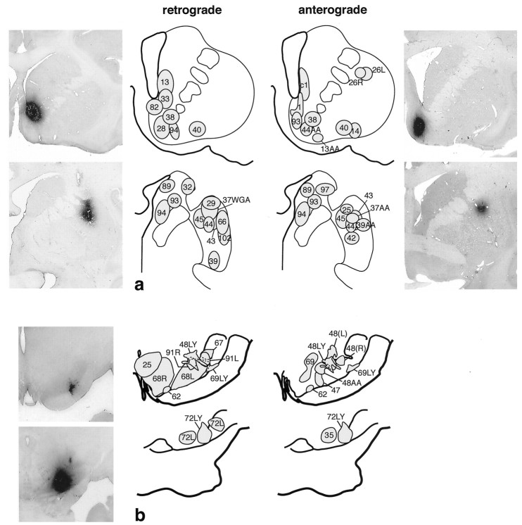
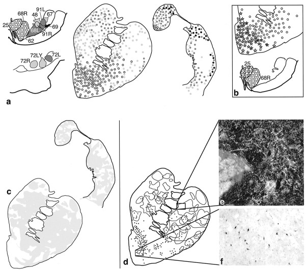
There were two sets of experiments. The first set placed bi-directional tracers into different regions of the striatum (see Fig.1a). These cases were analyzed first for the distribution of labeled cells in the frontal cortex. On the basis of the cortical labeling pattern, each injection site was classified as follows. (1) “Motor” striatum were injection sites that labeled cells primarily in frontal cortical areas 4 and 6 with few labeled cells in areas 9 and 46, and scattered cells, or none, in orbitofrontal regions or in areas 32, 25, 24, a or b; (2) “limbic” striatum were injection sites that labeled cells primarily in areas 32, 25, 24, a and b, and medial orbitofrontal cortex, areas 10, 14, and 13, with few labeled cells in areas 9 and 46 and none in areas 4 and 6. We defined the shell as the ventral striatal region that was calbindin (CaBP) negative and the rest of the ventromedial striatum as the “core” (Meredith et al., 1996). (3) Association areas comprised injection sites that labeled primarily areas 9 and 46. Each case was classified according to its cortical labeling pattern, and anterograde tracers were then placed into the striatum to match the retrograde placements in motor, limbic, or association areas. These cases were charted for cell and fiber labeling pattern in the midbrain. In some cases two tracers were injected into the same or different striatal regions in the same animal.
Fig. 1.
a, Summary of retrograde and anterograde striatal injections. Bi-directional tracer injection sites are shown on both anterograde and retrograde drawings. Photomicrographs are examples of individual injection sites at caudal and rostral levels of the striatum. b, Summary of retrograde and anterograde injections in the substantia nigra. Bi-directional tracers are used in both anterograde and retrograde injection sites. Photomicrographs are examples of individual injection sites at caudal and rostral levels of the substantia nigra.
The second set of experiments placed anterograde and bi-directional tracers in different regions of the ventral midbrain (see Fig.1b). The midbrain dopamine cells are divided into a dorsal and ventral tier. The dorsal tier, including the dorsal pars compacta and the ventral tegmental area (VTA), is calbindin positive. The ventral tier includes the densocellular region and the cell columns and is calbindin negative (Fallon et al., 1978; Gerfen et al., 1987; Lavoie and Parent, 1991; Lynd-Balta and Haber, 1994a; Haber et al., 1995b). Sections containing injection sites were counterstained for calbindin to determine their location.
Animals and procedures. Adult Macaques (_Mulata_and Nemistrina) were injected with one or more tracer molecules: anterograde tracers, _Phaseolus vulgaris_leucoagglutinin (PHA-L) and tritiated amino acids, and bi-directional tracers, wheat germ agglutinin conjugated to horseradish peroxidase (WGA/HRP), Lucifer yellow (LY), or fluorescein (FS) conjugated to dextran amine. After initial anesthesia with ketamine (10 mg/kg, i.m.), a deep surgical level of anesthesia was maintained with pentobarbital (initial dose 20 mg/kg, i.v., and maintained as needed). Targets were located using electrophysiological mapping. Serial electrode penetrations were made throughout the rostrocaudal and mediolateral extent of the striatum to identify neuronal activity based on patterns of electrophysiological recordings (Haber et al., 1993). The location of neurons encountered in a series of penetrations was used to prepare a map indicating the boundaries of different basal ganglia structures. The absence of cellular activity was noted in the area of fiber tracts, i.e., the corpus callosum, the internal capsule, and the anterior commissure. Accurate placement of the tracers was subsequently achieved by careful alignment of the injection cannulae with the electrode. Tritiated amino acids (tritiated leucine and tritiated proline, 50–80 mCi, in 200 nl saline; NEN, Boston, MA.), PHA-L, 80 nl of 2.5% in 0.05m Tris buffer (Vector Laboratories, Burlingame, CA.), LY, 20–40nl, FS, 40–50 nl, (10% in dH2O; Molecular Probes, Eugene, OR.), and HRP-WGA, 40–50 nl, (4% in H2O, Sigma, St. Louis, MO.) were pressure-injected into discrete regions of the striatum or midbrain. After an injection, the syringe remained in situ for 20–30 min to prevent leakage up the needle track. Nine to 14 days after surgery, the animals were again deeply anesthetized and perfused through the heart with saline followed by a 4% paraformaldehyde/1.5% sucrose solution in 0.1 m phosphate buffer, pH 7.4. The brains were cryoprotected in increasing gradients of sucrose (10, 20, and finally 30%). Serial sections of 50 μm were cut on a freezing microtome and processed for autoradiography or immunocytochemistry for WGA-HRP, PHA-L, LY, or FS. Sections were also double-labeled for two tracers (see below).
Sections for autoradiography were mounted on chrome-alum gelatin-coated slides and defatted in xylene overnight. Slides were dipped in Kodak NTB2 photographic emulsion and exposed for 4–6 months at −20°C in a light-tight box. The sections were then developed in Kodak D19 for 2.5 min., fixed, washed, and counterstained with cresyl violet. Sections to be immunoreacted with anti-PHA-L, anti-LY, anti-FS, or anti-HRP-WGA were rinsed in 0.1 m phosphate buffer, pH 7.4, with 0.1%m Triton X-100 (PBS-T), preincubated in 10% normal goat serum (NGS) diluted with PBS-T for 30 min, and then placed in the primary antisera, anti-LY or FS (1:1000, Molecular Probes), or anti-HRP-WGA (1:2000; Dako, Carpinteria, CA.), or anti-PHA-L (1:500; EY Labs, San Mateo, CA.) in NGS-PBS-T for four to five nights at 4°C. The avidin–biotin reaction (rabbit Vectastain ABC kit, Vector) was used to visualize the tracers. Staining was produced by incubating the tissue for 10–12 min in 3,3′ diaminobenzidine tetra-hydrochloride and 3% hydrogen peroxide and intensified with 1% cobalt chloride and 1% nickel ammonium sulfate to yield a black reaction product. Sections were rinsed, dehydrated, and coverslipped with Permount (Fisher Scientific, Pittsburgh, PA). Antisera to calbindin (Sigma) was used at 1:10,000 in PBS-T with 0.5% bovine serum albumin (BSA) (Sigma). Tissue was first incubated in PBS-T with 5% BSA for 1 hr, then incubated in primary antisera for four nights at 4°C and processed using the avidin–biotin reaction (mouse Vectastain ABC kit, Vector) as described above.
Analysis. Cases were eliminated from analysis if there was contamination of adjacent structures, including fiber tracks. Cell and fiber distributions in both the striatum and midbrain were charted for each case. To determine the scope of SNS interactions, we used different combinations of cases and analyzed experiments both individually and collectively in these groups. To create composites from all injection sites within a functional region, Nissl-stained midbrain or striatal sections were imported into the computer using NIH Image Software and a Hamamatsu camera (magnification 6.3×). Photomontage images were imported into the graphics program Canvas 5.0. Within this program, the following layers were created: layer 1, the photomontage of the Nissl-stained section; layer 2, a drawn outline of the section with internal landmarks such as the pars compacta, fascicles of the third nerve, the basis peduncle, the red nucleus, and the aqueduct; and layer 3, charts of the individual cells or fiber distributions. To evaluate the collective pathways from each striatal or midbrain region, a master chart was created for each rostral/caudal level charted. The master charts contained each individual case within its own layer. One Nissl photomontage for each level was imported into layer 1. The outline of each individual case along with its charted cell or fiber distributions was imported as a separate layer and superimposed on the master Nissl image. The outline for each case was aligned to best correspond to the outline of the master image. Once each case was imported, the individual outlines were eliminated, leaving the fiber and cell labeling for each case in its own layer. The relationship between the different input and output pathways across cases was analyzed by changing the visible layers. This allowed us to evaluate within and between each SNS system by combining data from discrete injections from different animals. Relationships between collective anterograde and retrograde injection sites were also compared with individual cases that contained bi-directional tracers in the relevant striatal regions.
RESULTS
Injection sites
Striatal cases were analyzed in which anterograde or retrograde tracer injections were placed into different striatal regions associated with limbic, cognitive, or motor corticostriatal pathways (Fig. 1a). There were 16 bi-directional and anterograde injection sites into different parts of the midbrain, including the dorsal tier [both the VTA and the dorsal SN pars compacta (SNc)] and the ventral tier (both the densocellular region and the cell columns) (Fig. 1b). Different tracer molecules, when placed in a similar position, resulted in a similar projection pattern. Thus, there were no differences between retrograde labeling patterns of HRP-WGA and LY; however, in general fewer cells were labeled using LY. Tritiated amino acids and LY injections resulted in denser terminal and fiber labeling than PHA-L injections, but with the same distribution pattern. There were no differences in labeling patterns or density between the two species of monkeys.
Taken together, there was a general inverse dorsal–ventral topography in both the striatonigral projections and nigrostriatal projections. Dorsal striatal injections resulted in labeled fibers and/or cells in the midbrain ventral to those labeled after a more ventral injection of tracer. Likewise, dorsal midbrain injections resulted in labeled fibers or cells in the ventral striatum. These general results are consistent with those reported previously (Szabo, 1962; Parent et al., 1984;Hedreen and DeLong, 1991; Lynd-Balta and Haber, 1994a,c; Parent and Hazrati, 1994). In this paper, we specify the characteristics and relationships between both limbs (the nigrostriatal and striatonigral) of the SNS system with particular reference to cortical innervation of the striatum.
Striatal cases
Distribution of labeled cells in cortex
Injection sites were first classified according to cortical labeling patterns (Table 1). Injections placed rostral to the anterior commissure into the nucleus accumbens, the ventromedial caudate nucleus, and ventral putamen labeled cortical cells in medial areas 32, 25, 24, a/b, and regions of orbitofrontal cortex (areas 14, 13a/b, 13, and 12). We referred to the region of these sites as the VMS. Within this group, three sites were confined to the shell (CaBP-poor region), without contamination of surrounding areas, and three were placed in the shell but not confined to it. The injection sites placed into the dorsal shell (or cone) labeled areas 25, Ia, and 14. A more ventral injection site also labeled these areas and areas 32, 24a/b, and 13a/b. Injections into the medial ventral caudate nucleus labeled additional areas 11 and 12. Central core injection sites labeled many cells in lateral regions, including area 13 and fewer in medial areas 25, Ia, and 14. Injection sites placed into the head and central body of the caudate nucleus and into the central, rostral putamen resulted in labeled cells concentrated in the dorsolateral prefrontal cortex (areas 9 and 46). Those that included the ventral part of the central striatum (CS) labeled cells not only in the dorsolateral prefrontal cortex but also in lateral parts of the orbital cortex. In contrast, sites placed more dorsally in the central striatum labeled some cells in area 8 and premotor areas in addition to dorsolateral prefrontal cortex. The region of injections sites that labeled primarily dorsolateral prefrontal cortex were referred to as the CS. Retrograde tracers placed in the dorsolateral striatum (DLS) rostrally and throughout most of the central and caudal putamen resulted in labeled cells in motor, premotor, and supplementary motor (SMA) cortex, and the cingulate motor area (areas 4, 6, and 24c). We referred to the region of these sites as the DLS. One injection site, placed in the head of the caudate but in its dorsolateral corner, labeled cells specifically in the pre-SMA, which borders dorsolateral prefrontal cortex. The more dorsal putamen injection sites labeled cells predominately in areas 6m and 6d; ventral putamen injection sites labeled cells primarily in area 6v.
Table 1.
Summary of the relative density of labeled cells in frontal cortical areas after retrograde injections into the VMS, CS, and DLS striatum
| Cortical area | Ventromedial cases (case#) | Central cases (case #) | Dorsolateral cases (case #) | ||||||||||||||||
|---|---|---|---|---|---|---|---|---|---|---|---|---|---|---|---|---|---|---|---|
| 82 | 28 | 33 | 13 | 94W | 38 | 35 | 94L | 96 | 89 | 32 | 39 | 45 | 43 | 44 | 29 | 37 | 66L | 102 | |
| 4 | − | − | − | − | − | − | − | − | − | − | − | − | + | + | ++ | +++ | ++++ | ++++ | ++++ |
| 6 | − | − | − | − | − | − | − | − | + | ++ | +++ | +++ | +++ | ++++ | ++++ | ++++ | ++ | + | + |
| 24c | − | − | − | − | − | − | − | − | + | + | − | ++ | + | + | + | ++ | + | + | +++ |
| 8 | − | − | − | − | − | − | − | + | ++++ | +++ | − | − | + | − | − | − | − | − | − |
| 9 | − | − | − | − | − | − | − | + | + | +++ | − | − | − | − | − | − | − | − | − |
| 45/46 | − | − | − | − | − | − | + | + | +++ | +++ | − | − | − | − | − | − | − | − | − |
| 12 | − | + | ++ | ++ | ++ | +++ | ++ | +++ | ++ | ++ | − | − | − | − | − | − | − | − | − |
| 11 | − | − | +++ | ++ | − | ++++ | + | + | − | − | − | − | − | − | − | − | − | − | − |
| 13 | − | − | + | − | ++ | ++++ | ++ | + | − | + | − | − | − | − | − | − | − | − | − |
| 13a/b | − | ++ | ++ | ++++ | ++ | ++ | + | − | − | − | − | − | − | − | − | − | − | − | − |
| 24a/b | − | ++++ | ++++ | ++++ | ++ | ++++ | +++ | − | − | ++ | + | − | − | − | − | − | − | − | − |
| 32 | + | ++++ | ++++ | ++++ | + | ++ | +++ | − | − | + | − | − | − | − | − | − | − | − | − |
| 14 | ++ | ++ | ++ | ++ | ++ | + | − | − | − | + | − | − | − | − | − | − | − | − | − |
| Ia | ++++ | +++ | ++ | +++ | ++ | ++ | − | − | − | − | − | − | − | − | − | − | − | − | − |
| 25 | ++++ | ++++ | ++++ | ++++ | + | ++ | ++ | − | − | − | − | − | − | − | − | − | − | − | − |
VMS pathways
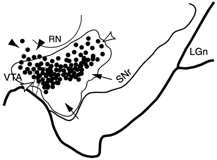
The VMS is that part of the striatum that receives input from the OMPFC, no input from motor or premotor areas, and little or no input from the dorsolateral prefrontal cortex. Projections from the VMS to the midbrain terminated in the dorsal midbrain, including both the dorsal tier and the dorsal part of the ventral tier extending into the medial and dorsal pars reticulata. Terminal fields compiled from all of the ventral striatal injection sites projected widely throughout the midbrain and were concentrated in the medial part rostrally and dorsolaterally at central and caudal levels (Fig.2). This general widespread terminal field is also evident after single injections (Fig.3c). The midbrain cells that projected to the VMS were concentrated in the medial half of the midbrain.
Fig. 2.
Schematic of the substantia nigra showing the combined distribution of terminal labeling (outlined area) and retrogradely labeled cells (black dots; each = 4–6 cells) after all VMS tracer injections. Black arrowheads indicate cells dorsal to VMS terminals. White arrowheads point to cells within the terminal field. Arrows indicate a ventral terminal region without cells that project to the VMS. LGn, Lateral geniculate nucleus; RN, red nucleus;SNr, substantia nigra, pars reticulata;VTA, ventral tegmental area.
Fig. 3.
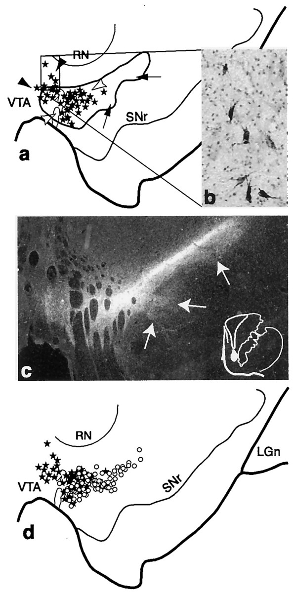
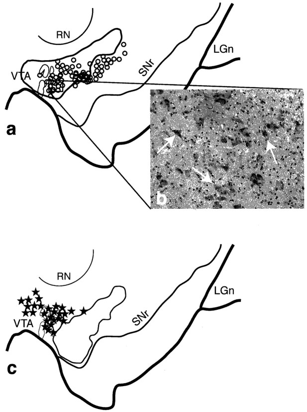
The shell SNS projection system illustrating the three components within the midbrain. a, Schematic of the midbrain showing the combined distribution of labeled terminals (outline) and cells (black stars; each = 4–6 cells) after all shell tracer injections. Black arrowheads indicate cells dorsal to terminals, white arrowheads indicate the region of cells within the shell terminal field, and arrows point to terminals ventral and lateral to cells projecting to the shell. b, Photomicrograph taken from the region outlined in a(box) of labeled cells after a WGA-HRP injection into the dorsal shell or cone region (case 82). c, Dark-field photomicrograph of the midbrain showing the distribution of terminals (silver grains) after a tritiated amino acid injection into the dorsal shell (injection site shown at right) (case 93AA). Note that some terminals extend into the dorsal part of the densocellular region (arrows). d, Schematic comparing the distribution of labeled cells from collective shell injections (stars) with those from collective core injections (open circles). One star or circle = 4–6 cells.LGn, Lateral geniculate nucleus; RN, red nucleus; SNr, substantia nigra, pars reticulata;VTA, ventral tegmental area.
Terminal labeling from the collective VMS injection sites overlapped extensively with the labeled cells that projected back to the ventral striatum (Fig. 2). However, the distribution of midbrain cells that projected to the VMS were more confined than the distribution of VMS projections to the midbrain, as evidenced also in individual cases. There were some labeled cells dorsal to the VMS terminal field. In addition, there was a large ventral terminal region, which did not contain labeled cells, that projected back to the VMS. Thus, there were three components in the SN of this projection system: Labeled cells that projected to the VMS that lie dorsal to the VMS efferent projection field (Fig. 2, black arrowheads); labeled cells that projected to the VMS that lie within the terminals fields of the VMS projection (Fig. 2, white arrowheads); and efferent VMS fibers that lie ventral to labeled cells projecting to the VMS (Fig. 2,arrows).
The shell SNS projection system lay in the most dorsal and medial part of the midbrain (Fig. 3). One interesting feature of the shell projection was that the fiber and cell labeling after injections centered in the shell did not obey the inverse dorsal–ventral topography. Labeled terminals and cells were always located in the dorsal SNc and in the VTA, regardless of the position of the injection site. Projections to the dorsal shell (or cone region) from the midbrain were concentrated near the midline, in the VTA (Fig.3b), whereas the ventral shell injection site resulted in labeled cells more ventrolaterally. Projections from the shell to the midbrain were also concentrated in the VTA and dorsal tier. However, there were also some terminals among and surrounding the dorsal part of the densocellular region (Fig. 3c, arrows). These terminals lay ventral to the cells that projected back to the shell. Projections to the core originated from cells in both the dorsal tier and the medial and dorsal densocellular region. Although this distribution of labeled cells overlapped with those cells projecting to the shell, it was somewhat ventral and more lateral to those cells projecting to the shell (Fig. 3d). Terminal fields from the core lay within and ventral to the cells that projected back to the core (Fig. 4).
Fig. 4.
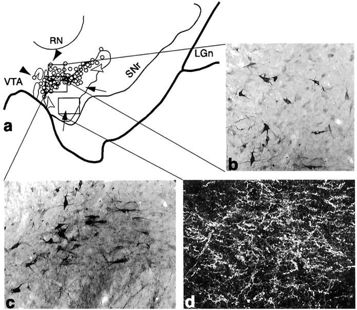
The core SNS projection system illustrating three components within the midbrain (Case 33). a, Schematic of the midbrain showing the combined distribution of labeled terminals (outline) and cells (circles; each = 4–6 cells) after all core tracer injections. Black arrowheads indicate labeled cells dorsal to terminals,white arrowheads indicate cells among terminals from the core, and arrows point to terminals ventral to cells projecting to the core. b–d, Photomicrographs of the three SNS projection components after an individual LY injection into the core. Boxed regions in a represent the approximate location of each photomicrograph from individual cases.b, Labeled cells not among terminals that project to the core. c, Labeled cells among labeled terminals.d, Dark-field photomicrograph of labeled efferent terminals in a region devoid of cells projecting to the core.LGn, Lateral geniculate nucleus; RN, red nucleus; SNr, substantia nigra, pars reticulata;VTA, ventral tegmental area.
Both the shell and core SNS projection systems contained the three components in the SN (Figs. 3, 4): a dorsal group of labeled cells that projected to the shell or core but did not lie within its reciprocal efferent projection (Figs. 3, 4, black arrowheads); a group of cells that did lie within its efferent terminal field (Figs. 3, 4,white arrowheads); and a terminal field that did not contain reciprocally connected labeled cells (Figs. 3, 4, arrows). Efferent fibers from the shell terminated both within the region of labeled cells projecting back to the shell and ventral to it (Fig.3a,c). Cells projecting to the core were located both within the terminal fields of the core and dorsal to it (Fig. 4). This dorsal group of cells lay within the ventral terminal field of the shell (Fig. 5a,b). In contrast, there was little overlap between efferent fibers originating from the core and labeled cells projecting to the shell (Fig. 5c). Labeled fibers from the core were also located ventral to the labeled cell population that projected back to the core.
Fig. 5.
Shell efferent projections overlap midbrain cells projecting to the core. a, Schematic of the midbrain illustrating the distribution terminals from the shell (outline) and cells that project to the core (circles; each = 4–6 cells) from collective tracer injections into the shell and core, respectively. b, Dark-field photomicrograph showing labeled terminals (silver grains), after an injection of tritiated amino acids in the shell, overlaying cells (arrows) in the midbrain region indicated by the_box_ in a. c, Core efferent projections do not overlap midbrain cells projecting to the shell. Schematic of the midbrain depicting the combined distributions of cells projecting to the shell (stars; each = 4–6 cells) and terminals from the core (outline) after collective injections into the shell and core, respectively. LGn, Lateral geniculate nucleus; RN, red nucleus;SNr, substantia nigra, pars reticulata;VTA, ventral tegmental area.
CS pathways
The CS is the striatal region that receives input primarily from areas 46 and 9. However, in all cases some labeled cells were found in either the OMPFC or in area 6. The central SNS field lay primarily within the densocellular region of the midbrain (Fig.6a_–_d). The CS efferent projection was extensive and terminated in the ventral part of the densocellular region and extended into the cell columns and surrounding pars reticulata. Labeled cells after retrograde tracer injections were also located throughout the densocellular region, in a wide medial–lateral area. As seen with the VMS, the collective CS SNS projection system also exhibited three components, a reciprocal and two nonreciprocal components. There were labeled cells located dorsal to the main CS terminal projection field (Fig.6a, black arrowheads, and b). Labeled cells were found embedded within the CS terminal fields (Fig.6a, white arrowheads, and c). Finally, terminals from the CS were found ventrally and not in close approximation to the main population of labeled cells that projected back to the CS (Fig. 6a, arrows, and_d_). Cells that projected to the CS were generally located lateral and ventral to those labeled after VMS injection sites with some overlap. A few labeled cells extended into the dorsal cell columns.
Fig. 6.
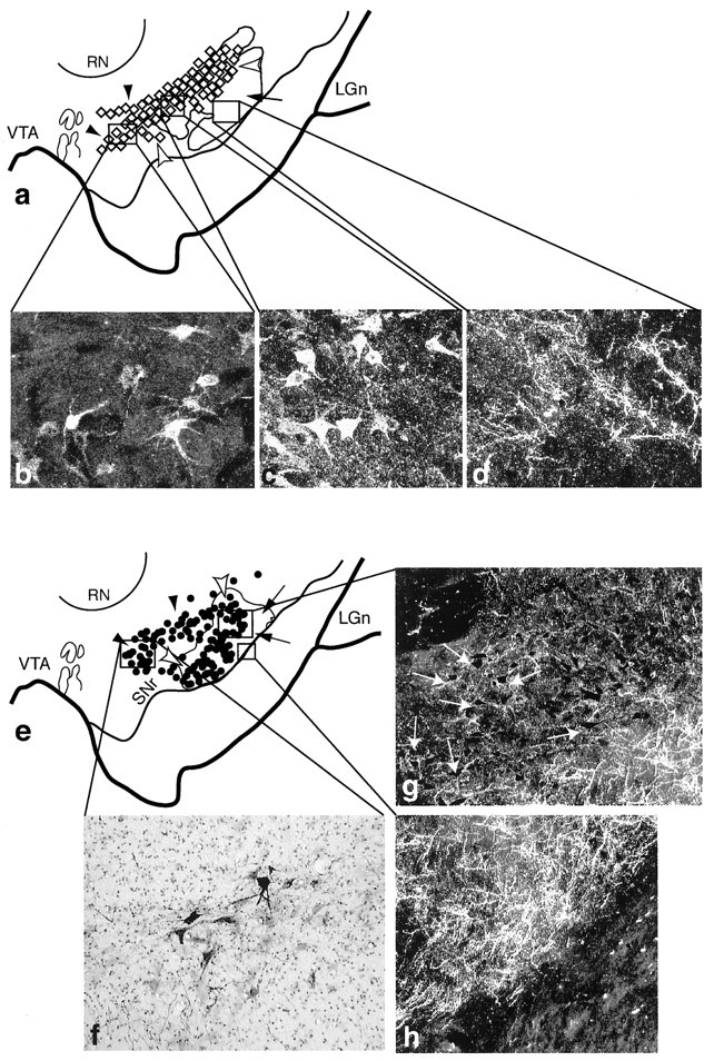
The central and dorsolateral SNS projection systems illustrating three components within the midbrain (cases 93 and 43, respectively). In schematics, black arrowheads_indicate labeled cells dorsal and medial to terminals, white arrowheads indicate labeled cells among labeled terminals, and_arrows point to terminals ventral to labeled cells.Boxed regions represent the approximate location of each photomicrograph from individual cases. a, Schematic of the midbrain showing the combined distribution of labeled terminals (outline) and cells (diamonds; each = 4–6 cells) after all CS tracer injections. b–d, Dark-field photomicrographs of the three central SNS projection components after an individual LY injection into the CS.b, Labeled cells, not among terminals that project to the CS. c, Labeled cells among labeled CS efferent terminals. d, Labeled CS efferent terminals in a region devoid of cells that project to CS. e, Schematic of the midbrain showing the combined distribution of labeled terminals (outline) and cells (dots; each = 4–6 cells) after all DLS tracer injections. f–h, Photomicrographs of the three SNS projection components after an LY injection into the DLS. f, Labeled cells, not among labeled terminals that project to the DLS. Dark-field images of cells (g, arrows) among labeled DLS efferent terminals. h, DLS efferent terminals in a region devoid of retrogradely labeled cells. LGn, Lateral geniculate nucleus; RN, red nucleus;SNr, substantia nigra, pars reticulata;VTA, ventral tegmental area.
DLS pathways
The DLS is the region that receives input from areas 4, 6, and 24c, but not from the OMPFC, and little if any from areas 9 and 46. Efferent projections from the dorsal striatum were concentrated in the ventral and lateral half of the SN. Unlike the widespread terminal fields of the VMS and CS pathways, the distribution of labeled efferent fibers from the DLS pathway was more restricted. In contrast to its limited efferent projection, the distribution of labeled cells after retrograde injections into the dorsal striatum were widely distributed both in the cell columns and in the densocellular area. Similar to the organization of the other SNS systems, there were three components in the midbrain (Fig. 6e): a dorsal group of cells that projected to the DLS but did not lie within its efferent projection field (Fig. 6e, black arrowheads, and_f_); a group of labeled cells that did lie within its efferent projection (Fig. 6e, unfilled arrowheads, and g); and a ventral terminal field that did not contain cells that projected back to the DLS (Fig.6e, arrows, and h). The labeled cells in the densocellular region comprise the group that did not lie with the efferent projection from the DLS. This dorsal population of cells was relatively large, compared with that after VMS injections. Together, the DLS SNS pathway was made up of a widespread cell population that projected to the DLS and a relatively confined DLS efferent terminal field.
Relationships between VMS, DLS, and CS pathways
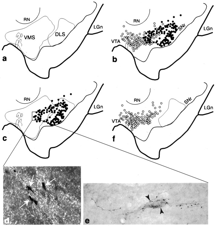
Projection fields from the VMS and DLS did not overlap in the midbrain (Fig. 7a). Projections from the midbrain to the VMS arose from the dorsal tier cells, whereas the cell columns projected to the DLS. The densocellular group contained cells projecting to either or both striatal regions (Fig. 7b). Although there was some overlap, cells in the densocellular region that projected to the VMS were generally located more medial and dorsal to those that projected to the DLS. Figure7c illustrates the relationship between VMS efferent fibers and cells that project to the DLS. VMS efferent fibers terminated in the region of the densocellular group, which contained some cells that project to the DLS. This densocellular group was not within the efferent fibers originating in the DLS. Cases in which an anterograde tracer was injected into the ventral striatum and a retrograde tracer into the dorsolateral striatum show some labeled cells in the densocellular part of the ventral tier embedded in anterograde-labeled fibers from the ventral striatum (Fig. 7c_–_e). In contrast, there was no overlap between the efferent projection from the DLS and the afferent projection to the VMS (Fig. 7f). This is supported by the fact that after retrograde injections into the VMS, there were no labeled cells embedded in efferent fibers from the DLS.
Fig. 7.
Relationship between the VMS and DLS SNS projection systems in the midbrain. a, Schematic of the midbrain illustrating the combined distributions of terminal fields (outlines) from collective VMS and DLS tracer injections. b, Schema comparing the combined distributions of labeled cells from collective VMS (open circles) and DLS (filled circles) injections. One filled/open circle = 4–6 cells. c, Schema showing the combined distribution of labeled cells after all DLS injections in relation to VMS and DLS terminal fields (outlines). d, Dark-field photomicrograph, taken from the boxed region in_c_, of labeled cells (arrows) embedded in terminals (silver grains) after WGA-HRP and tritiated amino acid injections into the DLS and VMS, respectively. e, Bright-field photomicrograph of a retrogradely labeled neuron, which projects to the DLS, surrounded by PHA-L-labeled fibers (arrowheads) with terminal boutons from the VMS.f, Schema showing the distribution of labeled cells for collective VMS injections in relation to DLS terminals.LGn, Lateral geniculate nucleus; RN, red nucleus; SNr, substantia nigra, pars reticulata;VTA, ventral tegmental area.
Figure 8 illustrates the relationship of the CS pathways to the VMS and DLS circuits. The majority of labeled cells in the central densocellular region were derived from the CS injection sites. Fibers from the VMS that projected into the densocellular region overlapped extensively with the region of cells that projected to the CS (Fig. 8a). This was particularly true of the dorsal population of CS-projecting cells that did not receive input from the CS. In contrast, there was little overlap between cells that projected to the VMS and efferent fibers of the CS (Fig. 8b). However, efferent fibers from the CS that terminated ventral to the population of cells that projected reciprocally to the CS did overlap with cells that projected to the DLS (Fig. 8c).
Fig. 8.
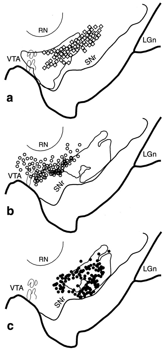
VMS–CS–DLS cell and terminal overlap in the midbrain. a, Schematic of the midbrain comparing the combined distribution of labeled terminals (outline) from all VMS tracer injections with that of cells (diamonds; each = 4–6 cells) that project to the CS. b, Schema comparing the combined distribution of labeled terminals (outline) from all CS tracer injections with that of cells (open circles; each = 4–6 cells) that project to the VMS. c, Schema comparing the combined distribution of labeled CS terminals (outline) with that of cells (black circles; each = 4–6 cells) that project to the DLS.LGn, Lateral geniculate nucleus; RN, red nucleus; SNr, substantia nigra, pars reticulata;VTA, ventral tegmental area.
Midbrain cases
Distribution of labeled cells
After retrograde tracer injections throughout the midbrain, the densest distribution of labeled cells was found in the VMS. In contrast, the DLS had the fewest labeled cells (Fig.9a). Injection sites throughout the dorsal and medial midbrain, including the dorsal tier and dorsal densocellular region, labeled cells in the VMS (Fig.9a, open circles and light gray dots). The shell region was extensively labeled only after an injection site located at the midline, in the VTA (Fig. 9b,stars). Although some labeled cells were found outside the shell region, they were mostly confined to the shell and extended only a short distance in the rostral striatum, with few labeled cells caudal to the anterior commissure. Ventromedial and dorsal injection sites labeled cells primarily in the core, outside of the shell, with some patches of labeled cells within the shell. Comparing a ventromedial injection site with one centered in the VTA, we found that labeled cells after the ventral sites were located primarily in the core outside the shell and showed a sharp contrast with the relatively unlabeled shell region (Fig. 9b). All cases that labeled cells in the ventral striatum also labeled cells in the ventromedial part of the body and tail of the caudate nucleus. The ventral injection sites did not result in labeled VMS cells.
Fig. 9.
a, Collective distribution of labeled cells in the precommissural and postcommissural striatum after retrograde injections into the midbrain. Rostral (top) and caudal (bottom) drawings of the midbrain showing the location of retrograde injection sites. Shading of sites corresponds to that of the cells in the striatal schematics. One dot = 4–6 cells. b, Magnified view of VMS illustrates the distribution of labeled cells at the border between the core and shell after injections into the medial SN (open circles) and VTA (stars). c, Combined chartings of terminal/fiber distributions in the striatum after all anterograde tracer injections into the midbrain. Note that fibers are distributed throughout the DLS and CS, whereas the VMS receives a more limited projection. d, Schematic of the rostral striatum showing the distribution of labeled cells and fibers after an injection of the bi-directional tracer LY into the densocellular region of the SN (Case 48LY). Note that LY-positive cells are primarily in the VMS and CS, whereas labeled fibers are primarily seen in the CS and DLS.e, Dark-field photomicrograph taken from the_boxed CS region_ in d showing dense LY-positive fibers, but no labeled cells. f, Photomicrograph taken from the boxed region in the VMS of labeled cells (from the boxed region in_d_).
The CS contained labeled cells after injection sites that were located in the central densocellular region (Fig. 9a,light and dark gray dots). Two ventral injection sites only labeled cells in the CS without tracer-positive cells in the VMS (Fig. 9a, dark gray dots). Four centrally located sites had labeled cells primarily in the CS but extended into the VMS. There were labeled cells in the DLS after only four ventral injection sites. Combination of the four cases showed that the number and distribution of labeled striatal cells were relatively sparse in the DLS, with large areas lacking labeled cells (Fig.9a, dark gray and black dots). Three injection sites included both the densocellular region and the cell columns and labeled both the DLS and the CS. Only one case had an injection site placed in the ventral pars reticulata. This injection site labeled cells only in the DLS (Fig. 9a, black dots).
Location of fiber distributions in the striatum
Figure 9c illustrates the distribution of the combined chartings of labeled fibers throughout the striatum after anterograde tracer injections into the midbrain. Eight injection sites were centered in different parts of the densocellular region: five included the dorsal densocellular region and parts of the dorsal tier, and three sites were placed more ventrally. Overall, fibers were distributed throughout the CS and the DLS. The VMS received the most limited projection.
Taken together, retrograde tracer sites centered in the densocellular region labeled cells primarily in the VMS and CS, with few labeled cells in the DLS. Conversely, anterograde injections centered in the densocellular region labeled fibers primarily in the CS and the DLS with relatively few fibers in the VMS. Injections of the bi-directional tracer LY into the densocellular region illustrates this projection pattern (Fig. 9d). There were relatively few labeled fibers in the VMS. Patches of fibers were concentrated in the CS, with some also in the DLS (Fig. 9e). In contrast, the distribution of labeled cells was most dense within the VMS (Fig.9f). There were some clusters of cells in the CS and no labeled cells in the DLS.
Summary
Projections from the VMS terminate widely throughout the midbrain, and even the shell has an extensive medial/lateral terminal field (Fig.4a,c). The retrograde experiments in the midbrain confirmed these findings. After most injection site locations, cells were labeled in the VMS. In contrast the DLS has a limited projection to the midbrain as evidenced by both the anterograde and retrograde experiments. The distribution of fibers and cells after anterograde and retrograde injections into the CS and midbrain, respectively, resulted in a pattern consistent with a projection to the CS primarily from the densocellular region and the dorsal part of the pars reticulata. Thus, with the exception of two retrograde injection sites in the midbrain, one placed into the ventral cell columns and one into the VTA, all cases showed some retrograde labeling in the CS (Fig. 9a). The shell received input primarily from the VTA. Cells projecting to the core also originated from the dorsal tier and to some extent from the dorsal part of the densocellular group. These results were confirmed by the anterograde tracer injections into the midbrain. Despite a wide range of injection site locations, there were few labeled fibers in the shell. There were more fibers distributed in the core, but these were also limited to a few injection site locations that included the dorsal tier and medial midbrain. In contrast, the CS receives input primarily from the ventral tier. Labeled cells projecting to the CS were widely distributed throughout a range of the densocellular group. Anterograde tracer injections into the midbrain confirmed these results. There were clusters of labeled fibers throughout the CS after many injection site locations into the midbrain. The ventral tier also projected to the DLS, with the cell columns projecting almost exclusively to the DLS.
DISCUSSION
SNS pathways
Each striatal injection site location was classified by its cortical input to the region and analyzed with respect to its relationship to limbic, associative, and motor cortices. On the basis of these results, we divided the striatum into the VMS, CS, and DLS. Previous studies have demonstrated the inverse dorsal–ventral topography of the striatonigral projection (Szabo, 1967, 1970, 1980;Selemon and Goldman-Rakic, 1990; Lynd-Balta and Haber, 1994c; Parent and Hazrati, 1994; Deniau et al., 1996) and of the nigrostriatal projection (Carpenter and Peter, 1971; Parent et al., 1983; Lynd-Balta and Haber, 1994a). When considered separately, each limb of the system creates a loose topographic organization demonstrating that the VTA and medial SN are associated with the limbic system, and the lateral and ventral SN are related to the associative and motor striatal regions. However, the VMS and DLS have contrasting relationships with the midbrain in that they differ in their relative proportional contribution to each limb of the SNS projection. Efferent projections from the VMS terminate throughout an extensive region of the dorsal midbrain, whereas the DLS projection is relatively limited to the ventrolateral SN. The CS pathway occupies an intermediate position between the VMS and DLS in the striatonigral pathway. Likewise, the ratio of nigrostriatal projections varies for different striatal regions. The VMS receives the most limited projection from the midbrain, whereas the DLS receives the largest. These differences in proportions significantly alter their relationship to the midbrain. The VMS influences a wide range of dopamine neurons but is itself influenced by a relatively limited group of dopamine cells. On the other hand, the DLS influences a limited midbrain region but is affected by a relatively large midbrain region.
Three SNS components in the SN
A major finding was that for each striatal region, the SNS projection system contained three SN components: a dorsal group of cells that does not lie within its reciprocal terminal field, a group of cells that does lie within its reciprocal terminal field, and a ventral component composed of the efferent terminals that do not contain a reciprocally connected group of labeled cells. Although the overlap between labeled cells and terminals at the light microscopic level does not demonstrate a direct synaptic connection, it is likely that this close relationship does indicate that the terminals in the region convey information relevant to the cells either directly or indirectly. Likewise, the lack of an overlap between terminal fields and labeled cells in the other two components is not necessarily evidence for a lack of connectivity, which might occur on distal dendrites. However, afferents nearest the cell bodies and proximal dendrites will be electrotonically closer to the soma and therefore likely to exert a much greater influence on spike activity than if they terminate distally (Spruston et al., 1994; Magee and Johnston, 1997). Thus, the three components of the SNS system are likely to represent different levels of interaction. Where cells and terminals overlap there is likely to be a more direct interface, which we refer to as a reciprocal connection. We refer to the dorsal and ventral components in which the cells and terminals do not overlap as nonreciprocal components. These three components for each SNS projection system occupy a different position within the midbrain. The VMS system lies dorsomedially, the DLS system lies ventrolaterally, and the CS system is positioned between the two (Fig.10).
Fig. 10.
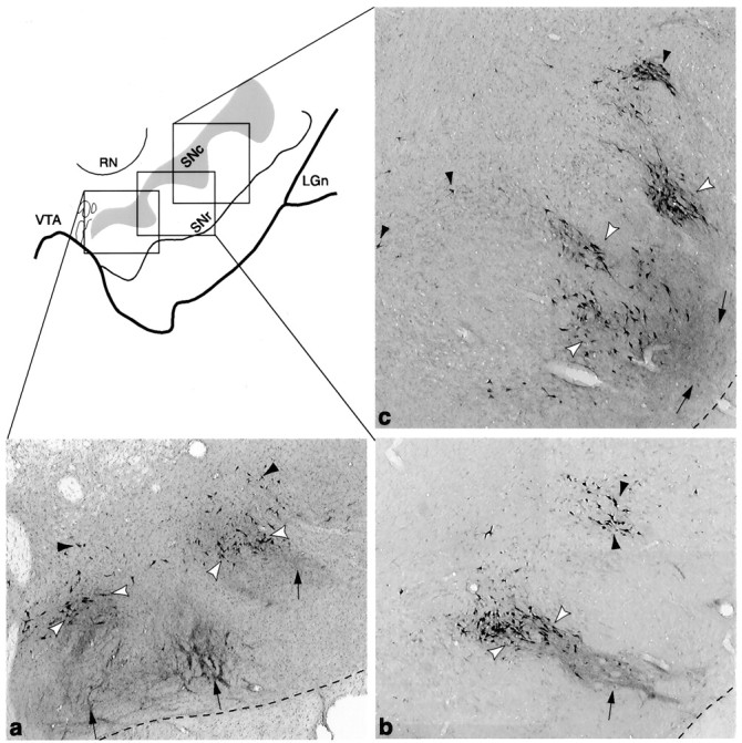
Schematic of the ventral midbrain, with photomicrographs from individual cases in which bi-directional tracers were placed in the VMS (a, case 33), CS (b, case 89), and DLS (c, case 102). Photomicrographs show the different positions of each SNS subcircuit. The VMS circuit (a) is located in a medial position with labeled cells in the dorsal region. The CS circuit (b) is located in a central position, with the labeled cells located in the densocellular region. The DLS circuit (c) is located laterally, with the labeled cells primarily ventral to the CS cells, extending deep into the cell columns. The three components of SNS for each region are also indicated: black arrowheads = labeled cells outside efferents fibers, white arrowheads = labeled cells within the terminal field of labeled efferent fibers, and_arrows_ = labeled fibers that project ventral to labeled cells.
The limbic–motor interface
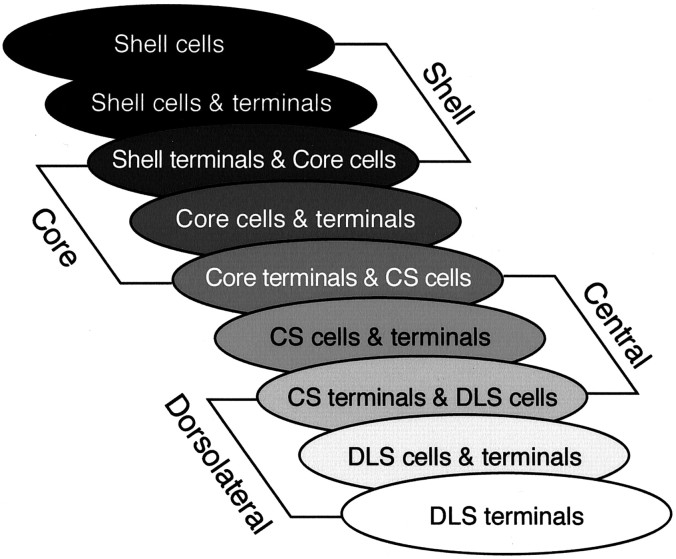
The observation that the dorsal striatum is modulated by the ventral striatum was a proposed mechanism by which limbic circuitry affects motor outcome directly (Nauta and Domesick, 1978; Nauta et al., 1978; Somogyi et al., 1981; Haber and Fudge, 1997). However, the definition of the dorsal striatum was broad and referred to the entire dorsal striatal area, outside the nucleus accumbens. In this study we have examined the SNS circuit based on its frontal cortical input, including associative areas of dorsolateral prefrontal cortex. The organization of cortical inputs to the striatum imposes a functional gradient from limbic to associative to motor domains. A similar gradient is imposed on the midbrain by virtue of the SNS system. The three components of each SNS system overlap each other, with the interface of CS projections positioned between the VMS and DLS (Fig.11). Interactions between functional regions of the striatum via the midbrain will therefore be most robust between adjacent striatal regions. On the basis of the large striatal area that receives nonlimbic and nonmotor input, the direct interaction between the limbic and motor systems is limited. With this arrangement, a model of a “one step” limbic to motor interface through the midbrain is unlikely to be a major connection.
Fig. 11.
Diagram of the three SNS components for each striatal region illustrating an overlapping and interdigitating system in the midbrain. The three midbrain components for each striatal region are represented by three ovals. The first oval in each set corresponds to the region of midbrain cells dorsal to its reciprocal afferent projection. The second oval corresponds to the region of cells within its reciprocal afferent projection. The third oval corresponds to the ventral region of nonreciprocal terminals that overlaps with cells of a more dorsal SNS system. Note that the third midbrain component of a striatal region overlaps the first component of the adjacent dorsal striatal region, resulting in stepwise feedforward projection from ventral to dorsal striatal regions.
An ascending midbrain spiral mediates limbic input to motor outcome
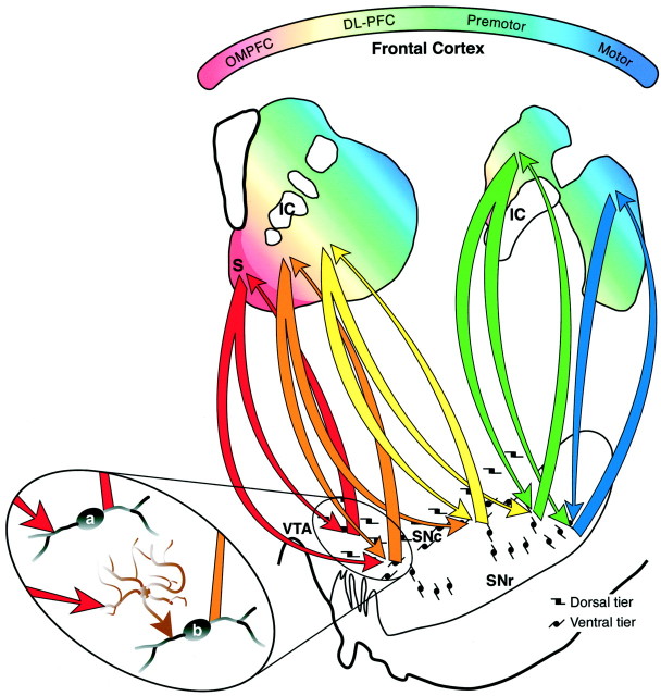
Rather than a direct limbic–motor connection, we propose that through these three midbrain components, information from the limbic system reaches the motor system through a series of connections (Fig.12). The shell receives forebrain input primarily from areas most closely associated with the limbic system and projects to the dorsal tier. However, its efferent projection also terminates lateral and ventral to the dorsal tier, in the dorsal densocellular region. This area of terminal projection does not project back to the shell but rather to the core. Through this connection, cortical information that influences the dorsal tier through the shell also modulates the densocellular region that projects to the core. The idea that the shell influences the core via a series of connections or loops has been supported by previous work suggesting that the limbic system influences frontal cortex through striatopallidal pathways (Zahm and Brog, 1992). The study presented here provides another route by which informa- tion from the shell is directed to the core. Projections to and from the core also form a reciprocal loop with the midbrain. In addition, the core projects ventral to its reciprocal component, which interfaces with the CS but not the core. The CS is reciprocally connected to the densocellular region but also projects to the ventral pars reticulata and the cell columns. The cell columns project to the DLS, with a reciprocal connection back to the cell columns and ventral pars reticulata. The confined distribution of efferent DLS fibers limits the influence of the motor striatum to a relatively small region involving the cell columns and the pars reticulata. Taken together, the interface between different striatal regions via the midbrain DA cells is organized in an ascending spiral interconnecting different functional regions of the striatum (Fig. 12). Thus, rather than a direct limbic–motor interface, information flows through several circuits to reach the motor striatum.
Fig. 12.
Diagram of the organization of SNS projections. The colored gradient in rostral and caudal schematics of the striatum illustrates the organization of functional corticostriatal inputs (red = limbic, green = associative, blue = motor). The shell receives forebrain input primarily from the amygdala, hippocampus, and cortical areas 25 and Ia. The core receives input from the entire OMPFC. The dorsolateral prefrontal cortex projects to the central striatum and premotor and motor cortex projects to the dorsolateral striatum. Midbrain projections from the shell target both the VTA and ventromedial SNc (red arrows). Midbrain projections from the VTA to the shell form a “closed,” reciprocal SNS loop (red arrow). Projections from the medial SN feedforward to the core forming the first part of a spiral (orange arrow). The spiral continues through the SNS projections (yellow and green arrows) with pathways originating in the core and projecting more dorsally (blue arrows). In this way ventral striatal regions influence more dorsal striatal regions via spiraling SNS projections.Magnified oval region shows a hypothetical model of the synaptic interactions of SNS projections in reciprocal versus feedforward loops. The reciprocal component (red arrows) of each limb of the SNS projection terminates directly (a) on a dopamine cell, resulting in inhibition. The nonreciprocal, or feedforward, component (orange arrow) terminates indirectly (b) on a dopamine cell via a GABAergic interneuron (brown cell), resulting in disinhibition and facilitation of dopaminergic cell burst firing. DL-PFC, Dorsolateral prefrontal cortex; IC, internal capsule;OMPFC, orbital and medial prefrontal cortex;S, shell; SNc, substantia nigra, pars compacta; SNr, substantia nigra, pars reticulata;VTA, ventral tegmental area.
Functional considerations
Most of the ventral midbrain cells that project to the striatum are dopaminergic and play a key role in the acquisition of newly acquired behaviors. These cells discharge when presented with relevant stimuli for which a response is required. However, when the animal is overtrained, cells no longer respond, suggesting that it is not the movement but the relevance of the stimulus that is important (Schultz, 1992; Schultz et al., 1993; Wilson et al., 1995; Richardson and Gratton, 1996). Although afferent control of the dopamine neurons arises from a number of structures (Smith and Grace, 1992), the striatum is a major source. The striatum inhibits neurons in both the pars compacta and the pars reticulata. However, stimulation of the striatum can also lead to an increase in dopamine firing through inhibition of GABAergic interneurons (or pars reticulata cells) that terminate on dopaminergic cells and dendrites, resulting in disinhibition of pars compacta cells (Francois et al., 1979; Grace and Bunney, 1979, 1995; Johnson and North, 1992). This dual effect of both inhibition and disinhibition may be an important mechanism underlying the ascending SNS spiral control of information flow. Striatal response to dopamine is heterogeneous and determined by multiple variables, including complex interactions between several receptors (Di Chiara et al., 1994; Starr, 1995; Arbuthnott and Wickens, 1996; Wickens et al., 1996; Calabresi et al., 1997). Converging evidence indicates that tonic release of dopamine attenuates medium spiny neuronal response, whereas phasic release potentiates striatal response (Cepeda and Levine, 1998). In this way dopamine can both inhibit background corticostriatal input and facilitate (and therefore “focus”) specific corticostriatal synaptic transmission. If the reciprocal component of each limb of the spiral terminated directly on a dopamine cell, it would result in inhibition of dopamine burst firing (Fig. 12). Conversely, the nonreciprocal feedforward component of the ascending spiral might terminate on GABAergic interneurons and result in disinhibition and an increase of burst firing. Each component of information (from limbic to motor outcome) would send an inhibitory feedback response but facilitate transfer of information to the next step in the spiral (via disinhibition). Because information about potential reward of a specific behavior from the shell is conveyed to the midbrain, it would inhibit additional information flow from the shell via the reciprocal connection. The nonreciprocal feedforward projection, terminating in proximity to cells projecting to the core, would increase DA burst firing in the core via disinhibition. The reciprocal projection to the core also inhibits its midbrain feedback, but via the GABAergic interneuron it disinhibits cells projecting to the CS. Thus information transfer continues from the core to the CS, through the CS to the DLS and final motor outcome (Fig. 12).
The basal ganglia link between motivation and motor outcomes has focused primarily on pathways of the nucleus accumbens (Mogenson et al., 1980, 1993; Groenewegen et al., 1996). Behavioral studies of dopamine pathways have lead to the association of the mesolimbic pathway and nigrostriatal pathway with reward and motor activity, respectively. Although the role of dopamine and reward is well established (Wise and Rompre, 1989), its primary function is to direct attention to important stimuli likely to bring about a desired outcome (Ljungberg et al., 1992; Schultz et al., 1997). This requires processing a complex chain of events beginning with motivation and proceeding through cognitive processing that shapes final motor outcomes, a sequence reflected in the feedforward organization of the SNS connections.
Footnotes
This work was supported by National Institutes of Health Grants MH45573 and NS22511 (S.N.H.) and MH11661 (N.R.M.).
Correspondence should be addressed to Dr. Suzanne N. Haber, Department of Neurobiology and Anatomy, University of Rochester School of Medicine, 601 Elmwood Avenue, Rochester, NY 14642. E-mail:Suzanne_Haber@urmc.rochester.edu.
REFERENCES
- 1.Arbuthnott GW, Wickens JR. Dopamine cells are neurones too. Trends Neurosci. 1996;19:279–280. doi: 10.1016/S0166-2236(96)20028-1. [DOI] [PubMed] [Google Scholar]
- 2.Calabresi P, Pisani A, Centonze D, Bernardi G. Synaptic plasticity and physiological interactions between dopamine and glutamate in the striatum. Neurosci Biobehav Rev. 1997;21:519–523. doi: 10.1016/s0149-7634(96)00029-2. [DOI] [PubMed] [Google Scholar]
- 3.Carmichael ST, Price JL. Architectonic subdivision of the orbital and medial prefrontal cortex in the macaque monkey. J Comp Neurol. 1994;346:366–402. doi: 10.1002/cne.903460305. [DOI] [PubMed] [Google Scholar]
- 4.Carmichael ST, Price JL. Limbic connections of the orbital and medial prefrontal cortex in macaque monkeys. J Comp Neurol. 1996;363:615–641. doi: 10.1002/cne.903630408. [DOI] [PubMed] [Google Scholar]
- 5.Carpenter MB, Peter P. Nigrostriatal and nigrothalamic fibers in the rhesus monkey. J Comp Neurol. 1971;144:93–116. doi: 10.1002/cne.901440105. [DOI] [PubMed] [Google Scholar]
- 6.Cepeda C, Levine MS. Dopamine and N-methyl-d-aspartate receptor interactions in the neostriatum. Dev Neurosci. 1998;20:1–18. doi: 10.1159/000017294. [DOI] [PubMed] [Google Scholar]
- 7.Chikama M, McFarland N, Amaral DG, Haber SN. Insular cortical projections to functional regions of the striatum correlate with cortical cytoarchitectonic organization in the primate. J Neurosci. 1997;17:9686–9705. doi: 10.1523/JNEUROSCI.17-24-09686.1997. [DOI] [PMC free article] [PubMed] [Google Scholar]
- 8.Deniau JM, Menetrey A, Charpier S. The lamellar organization of the rat substantia nigra pars reticulata: segregated patterns of striatal afferents and relationship to the topography of corticostriatal projections. Neuroscience. 1996;73:761–781. doi: 10.1016/0306-4522(96)00088-7. [DOI] [PubMed] [Google Scholar]
- 9.Di Chiara G, Morelli M, Consolo S. Modulatory functions of neurotransmitters in the striatum: ACh/dopamine/NMDA interactions. Trends Neurosci. 1994;17:228–233. doi: 10.1016/0166-2236(94)90005-1. [DOI] [PubMed] [Google Scholar]
- 10.Eslinger PJ, Damasio AR. Severe disturbance of higher cognition after bilateral frontal lobe ablation: patient EVR. Neurology. 1985;35:1731–1741. doi: 10.1212/wnl.35.12.1731. [DOI] [PubMed] [Google Scholar]
- 11.Fallon JH, Riley JN, Moore RY. Substantia nigra dopamine neurons: separate populations project to neostriatum and allocortex. Neurosci Lett. 1978;7:157–162. doi: 10.1016/0304-3940(78)90160-x. [DOI] [PubMed] [Google Scholar]
- 12.Flaherty AW, Graybiel AM. Input-output organization of the sensorimotor striatum in the squirrel monkey. J Neurosci. 1994;14:599–610. doi: 10.1523/JNEUROSCI.14-02-00599.1994. [DOI] [PMC free article] [PubMed] [Google Scholar]
- 13.Francois C, Percheron G, Yelnik J, Heyner S. Demonstration of the existence of small local circuit neurons in the Golgi-stained primate substantia nigra. Brain Res. 1979;172:160–164. doi: 10.1016/0006-8993(79)90905-3. [DOI] [PubMed] [Google Scholar]
- 14.Fuster JM. The prefrontal cortex anatomy, physiology, and neuropsychology of the frontal lobe. Raven; New York: 1989. Lesion studies. pp. 51–82. [Google Scholar]
- 15.Gerfen CR, Wilson CJ. Integrated systems of the CNS (Part III). In: Swanson LW, Bjorklund A, Hokfelt T, editors. Handbook of chemical neuroanatomy, Vol 12. Elsevier; New York: 1996. pp. 371–468. [Google Scholar]
- 16.Gerfen CR, Herkenham M, Thibault J. The neostriatal mosaic: II. Patch- and matrix-directed mesostriatal dopaminergic and non-dopaminergic systems. J Neurosci. 1987;7:3915–3934. doi: 10.1523/JNEUROSCI.07-12-03915.1987. [DOI] [PMC free article] [PubMed] [Google Scholar]
- 17.Giménez-Amaya JM, McFarland NR, de las Heras S, Haber SN. Organization of thalamic projections to the ventral striatum in the primate. J Comp Neurol. 1995;354:127–149. doi: 10.1002/cne.903540109. [DOI] [PubMed] [Google Scholar]
- 18.Goldman-Rakic PS. Working memory dysfunction in schizophrenia. J Neuropsychiatry Clin Neurosci. 1994;6:348–357. doi: 10.1176/jnp.6.4.348. [DOI] [PubMed] [Google Scholar]
- 19.Goldman-Rakic PS, Selemon LD. Topography of corticostriatal projections in nonhuman primates and implications for functional parcellation of the neostriatum. In: Jones EG, Peters A, editors. Cerebral cortex, Vol 5. Plenum; New York: 1986. pp. 447–466. [Google Scholar]
- 20.Grace AA, Bunney BS. Paradoxical GABA excitation of nigral dopaminergic cells: indirect mediation through reticulata inhibitory neurons. Eur J Pharmacol. 1979;59:211–218. doi: 10.1016/0014-2999(79)90283-8. [DOI] [PubMed] [Google Scholar]
- 21.Grace AA, Bunney BS. Electrophysiological properties of midbrain dopamine neurons. In: Bloom FE, Kupfer DJ, editors. Psychopharmacology: The fourth generation of progress. Raven; New York: 1995. pp. 163–177. [Google Scholar]
- 22.Groenewegen HJ, Wright CI, Beijer AVJ. The nucleus accumbens: gateway for limbic structures to reach the motor system? In: Holstege G, Bandler R, Saper CP, editors. Progress in brain research. Elsevier Science; New York: 1996. pp. 485–511. [DOI] [PubMed] [Google Scholar]
- 23.Haber SN, Fudge JL. The primate substantia nigra and VTA: integrative circuitry and function. Crit Rev Neurobiol. 1997;11:323–342. doi: 10.1615/critrevneurobiol.v11.i4.40. [DOI] [PubMed] [Google Scholar]
- 24.Haber SN, Lynd-Balta E, Mitchell SJ. The organization of the descending ventral pallidal projections in the monkey. J Comp Neurol. 1993;329:111–129. doi: 10.1002/cne.903290108. [DOI] [PubMed] [Google Scholar]
- 25.Haber SN, Kunishio K, Mizobuchi M, Lynd-Balta E. The orbital and medial prefrontal circuit through the primate basal ganglia. J Neurosci. 1995a;15:4851–4867. doi: 10.1523/JNEUROSCI.15-07-04851.1995. [DOI] [PMC free article] [PubMed] [Google Scholar]
- 26.Haber SN, Ryoo H, Cox C, Lu W. Subsets of midbrain dopaminergic neurons in monkeys are distinguished by different levels of mRNA for the dopamine transporter: comparison with the mRNA for the D2 receptor, tyrosine hydroxylase and calbindin immunoreactivity. J Comp Neurol. 1995b;362:400–410. doi: 10.1002/cne.903620308. [DOI] [PubMed] [Google Scholar]
- 27.Hedreen JC, DeLong MR. Organization of striatopallidal, striatonigal, and nigrostriatal projections in the Macaque. J Comp Neurol. 1991;304:569–595. doi: 10.1002/cne.903040406. [DOI] [PubMed] [Google Scholar]
- 28.Heimer L, Switzer RD, Van Hoesen GW. Ventral striatum and ventral pallidum. Components of the motor system? Trends Neurosci. 1982;5:83–87. [Google Scholar]
- 29.Heimer L, Alheid GF, de Olmos JS, Groenewegen HJ, Haber SN, Harlan RE, Zahm DS. The accumbens: beyond the core-shell dichotomy. J Neuropsychiatry Clin Neurosci. 1997;9:354–381. doi: 10.1176/jnp.9.3.354. [DOI] [PubMed] [Google Scholar]
- 30.Jimenez-Castellanos J, Graybiel AM. Evidence that histochemically distinct zones of the primate substantia nigra pars compacta are related to patterned distributions of nigrostriatal projection neurons and striatonigral fibers. Exp Brain Res. 1989;74:227–238. doi: 10.1007/BF00248855. [DOI] [PubMed] [Google Scholar]
- 31.Johnson SW, North RA. Two types of neurone in the rat ventral tegmental area and their synaptic inputs. J Physiol (Lond) 1992;450:455–468. doi: 10.1113/jphysiol.1992.sp019136. [DOI] [PMC free article] [PubMed] [Google Scholar]
- 32.Kalivas PW, Churchill L, Klitenick MA. The circuitry mediating the translation of motivational stimuli into adaptive motor responses. In: Kalivas PW, Barnes CD, editors. Limbic motor circuits and neuropsychiatry. CRC; Boca Raton, FL: 1993. pp. 237–275. [Google Scholar]
- 33.Kunishio K, Haber SN. Primate cingulostriatal projection: limbic striatal versus sensorimotor striatal input. J Comp Neurol. 1994;350:337–356. doi: 10.1002/cne.903500302. [DOI] [PubMed] [Google Scholar]
- 34.Künzle H. Bilateral projections from precentral motor cortex to the putamen and other parts of the basal ganglia. An autoradiographic study in Macaca fascicularis. Brain Res. 1975;88:195–209. doi: 10.1016/0006-8993(75)90384-4. [DOI] [PubMed] [Google Scholar]
- 35.Künzle H. An autoradiographic analysis of the efferent connections from premotor and adjacent prefrontal regions (areas 6 and 9) in Macaca fascicularis. Brain Behav Evol. 1978;15:185–234. doi: 10.1159/000123779. [DOI] [PubMed] [Google Scholar]
- 36.Lavoie B, Parent A. Dopaminergic neurons expressing calbindin in normal and parkinsonian monkeys. NeuroReport. 1991;2:601–604. doi: 10.1097/00001756-199110000-00012. [DOI] [PubMed] [Google Scholar]
- 37.Ljungberg T, Apicella P, Schultz W. Responses of monkey dopamine neurons during learning of behavioral reactions. J Neurophysiol. 1992;67:145–163. doi: 10.1152/jn.1992.67.1.145. [DOI] [PubMed] [Google Scholar]
- 38.Lynd-Balta E, Haber SN. The organization of midbrain projections to the striatum in the primate: sensorimotor-related striatum versus ventral striatum. Neuroscience. 1994a;59:625–640. doi: 10.1016/0306-4522(94)90182-1. [DOI] [PubMed] [Google Scholar]
- 39.Lynd-Balta E, Haber SN. The organization of midbrain projections to the ventral striatum in the primate. Neuroscience. 1994b;59:609–623. doi: 10.1016/0306-4522(94)90181-3. [DOI] [PubMed] [Google Scholar]
- 40.Lynd-Balta E, Haber SN. Primate striatonigral projections: a comparison of the sensorimotor-related striatum and the ventral striatum. J Comp Neurol. 1994c;343:1–17. doi: 10.1002/cne.903450407. [DOI] [PubMed] [Google Scholar]
- 41.Magee JC, Johnston D. A synaptically controlled, associative signal for Hebbian plasticity in hippocampal neurons. Science. 1997;275:209–213. doi: 10.1126/science.275.5297.209. [DOI] [PubMed] [Google Scholar]
- 42.Meredith GE, Pattiselanno A, Groenewegen HJ, Haber SN. Shell and core in monkey and human nucleus accumbens identified with antibodies to calbindin-D28k. J Comp Neurol. 1996;365:628–639. doi: 10.1002/(SICI)1096-9861(19960219)365:4<628::AID-CNE9>3.0.CO;2-6. [DOI] [PubMed] [Google Scholar]
- 43.Mogenson GJ, Jones DL, Yim CY. From motivation to action: functional interface between the limbic system and the motor system. Prog Neurobiol. 1980;14:69–97. doi: 10.1016/0301-0082(80)90018-0. [DOI] [PubMed] [Google Scholar]
- 44.Mogenson GJ, Brudzynski SM, Wu M, Yang CR, Yim CCY. From motivation to action: a review of dopaminergic regulation of limbic-nucleus accumbens-pedunculopontine nucleus circuitries involved in limbic-motor integration. In: Kalivas PW, Barnes CD, editors. Limbic motor circuits and neuropsychiatry. CRC; Boca Raton, FL: 1993. pp. 193–236. [Google Scholar]
- 45.Nauta WJH, Domesick VB. Crossroads of limbic and striatal circuitry: hypothalamic-nigral connections. In: Livingston KE, Hornykiewicz O, editors. Limbic mechanisms. Plenum; New York: 1978. pp. 75–93. [Google Scholar]
- 46.Nauta WJH, Smith GP, Faull RLM, Domesick VB. Efferent connections and nigral afferents of the nucleus accumbens septi in the rat. Neuroscience. 1978;3:385–401. doi: 10.1016/0306-4522(78)90041-6. [DOI] [PubMed] [Google Scholar]
- 47.Parent A, Hazrati L-N. Multiple striatal representation in primate substantia nigra. J Comp Neurol. 1994;344:305–320. doi: 10.1002/cne.903440211. [DOI] [PubMed] [Google Scholar]
- 48.Parent A, Mackey A, De Bellefeuille L. The subcortical afferents to caudate nucleus and putamen in primate: a fluorescence retrograde double labeling study. Neuroscience. 1983;10:1137–1150. doi: 10.1016/0306-4522(83)90104-5. [DOI] [PubMed] [Google Scholar]
- 49.Parent A, Bouchard C, Smith Y. The striatopallidal and striatonigral projections: two distinct fiber systems in primate. Brain Res. 1984;303:385–390. doi: 10.1016/0006-8993(84)91224-1. [DOI] [PubMed] [Google Scholar]
- 50.Richardson NR, Gratton A. Behavior-relevant changes in nucleus accumbens dopamine transmission elicited by food reinforcement: an electrochemical study in rat. J Neurosci. 1996;16:8160–8169. doi: 10.1523/JNEUROSCI.16-24-08160.1996. [DOI] [PMC free article] [PubMed] [Google Scholar]
- 51.Rolls ET, Burton MJ, Mora F. Neurophysiological analysis of brain-stimulation reward in the monkey. Brain Res. 1980;194:339–357. doi: 10.1016/0006-8993(80)91216-0. [DOI] [PubMed] [Google Scholar]
- 52.Schultz W. Activity of dopamine neurons in the behaving primate. Semin Neurosci. 1992;4:129–138. [Google Scholar]
- 53.Schultz W, Apicella P, Ljungberg T. Responses of monkey dopamine neurons to reward and conditioned stimuli during successive steps of learning a delayed response task. J Neurosci. 1993;13:900–913. doi: 10.1523/JNEUROSCI.13-03-00900.1993. [DOI] [PMC free article] [PubMed] [Google Scholar]
- 54.Schultz W, Dayan P, Montague PR. A neural substrate of prediction and reward. Science. 1997;275:1593–1599. doi: 10.1126/science.275.5306.1593. [DOI] [PubMed] [Google Scholar]
- 55.Selemon LD, Goldman-Rakic PS. Topographic intermingling of striatonigral and striatopallidal neurons in the rhesus monkey. J Comp Neurol. 1990;297:359–376. doi: 10.1002/cne.902970304. [DOI] [PubMed] [Google Scholar]
- 56.Smith ID, Grace AA. Role of subthalamic nucleus in the regulation of nigral dopamine neuron activity. Synapse. 1992;12:287–303. doi: 10.1002/syn.890120406. [DOI] [PubMed] [Google Scholar]
- 57.Somogyi P, Bolam JP, Totterdell S, Smith AD. Monosynaptic input from the nucleus accumbens-ventral striatum region to retrogradely labelled nigrostriatal neurones. Brain Res. 1981;217:245–263. doi: 10.1016/0006-8993(81)90002-0. [DOI] [PubMed] [Google Scholar]
- 58.Spruston N, Jaffe DB, Johnston D. Dendritic attenuation of synaptic potentials and currents: the role of passive membrane properties. Trends Neurosci. 1994;17:161–166. doi: 10.1016/0166-2236(94)90094-9. [DOI] [PubMed] [Google Scholar]
- 59.Starr MS. Glutamate/dopamine D1/D2 balance in the basal ganglia and its relevance to Parkinson's disease. Synapse. 1995;19:264–293. doi: 10.1002/syn.890190405. [DOI] [PubMed] [Google Scholar]
- 60.Szabo J. Topical distribution of the striatal efferents in the monkey. Exp Neurol. 1962;5:21–36. [Google Scholar]
- 61.Szabo J. The efferent projections of the putamen in the monkey. Exp Neurol. 1967;19:463–476. doi: 10.1016/0014-4886(67)90166-5. [DOI] [PubMed] [Google Scholar]
- 62.Szabo J. Projections from the body of the caudate nucleus in the rhesus monkey. Exp Neurol. 1970;27:1–15. doi: 10.1016/0014-4886(70)90196-2. [DOI] [PubMed] [Google Scholar]
- 63.Szabo J. Organization of the ascending striatal afferents in monkeys. J Comp Neurol. 1980;189:307–321. doi: 10.1002/cne.901890207. [DOI] [PubMed] [Google Scholar]
- 64.Voorn P, Brady LS, Berendse HW, Richfield EK. Densitometrical analysis of opioid receptor ligand binding in the human striatum: I. Distribution of μ opioid receptor defines shell and core of the ventral striatum. Neuroscience. 1996;75:777–792. doi: 10.1016/0306-4522(96)00271-0. [DOI] [PubMed] [Google Scholar]
- 65.Wickens JR, Begg AJ, Arbuthnott GW. Dopamine reverses the depression of rat corticostriatal synapses which normally follows high-frequency stimulation of cortex in vitro. Neuroscience. 1996;70:1–5. doi: 10.1016/0306-4522(95)00436-m. [DOI] [PubMed] [Google Scholar]
- 66.Wilson C, Nomikos GG, Collu M, Fibiger HC. Dopaminergic correlates of motivated behavior: importance of drive. J Neurosci. 1995;15:5169–5178. doi: 10.1523/JNEUROSCI.15-07-05169.1995. [DOI] [PMC free article] [PubMed] [Google Scholar]
- 67.Wise RA, Rompre PP. Brain dopamine and reward. Annu Rev Psychol. 1989;40:191–225. doi: 10.1146/annurev.ps.40.020189.001203. [DOI] [PubMed] [Google Scholar]
- 68.Yamaguchi S, Kobayashi S. Contributions of the dopaminergic system to voluntary and automatic orienting of visuospatial attention. J Neurosci. 1998;18:1869–1878. doi: 10.1523/JNEUROSCI.18-05-01869.1998. [DOI] [PMC free article] [PubMed] [Google Scholar]
- 69.Zaborszky L, Alheid GF, Beinfeld MC, Eiden LE, Heimer L, Palkovits M. Cholecystokinin innervation of the ventral striatum: a morphological and radioimmunological study. Neuroscience. 1985;14:427–453. doi: 10.1016/0306-4522(85)90302-1. [DOI] [PubMed] [Google Scholar]
- 70.Zahm DS, Brog JS. On the significance of subterritories in the “accumbens” part of the rat ventral striatum. Neuroscience. 1992;50:751–767. doi: 10.1016/0306-4522(92)90202-d. [DOI] [PubMed] [Google Scholar]
