Measuring the elasticity of clathrin-coated vesicles via atomic force microscopy - PubMed (original) (raw)
Measuring the elasticity of clathrin-coated vesicles via atomic force microscopy
Albert J Jin et al. Biophys J. 2006.
Abstract
Using a new scheme based on atomic force microscopy (AFM), we investigate mechanical properties of clathrin-coated vesicles (CCVs). CCVs are multicomponent protein and lipid complexes of approximately 100 nm diameter that are implicated in many essential cell-trafficking processes. Our AFM imaging resolves clathrin lattice polygons and provides height deformation in quantitative response to AFM-substrate compression force. We model CCVs as multilayered elastic spherical shells and, from AFM measurements, estimate their bending rigidity to be 285 +/- 30 k(B)T, i.e., approximately 20 times that of either the outer clathrin cage or inner vesicle membrane. Further analysis reveals a flexible coupling between the clathrin coat and the membrane, a structural property whose modulation may affect vesicle biogenesis and cellular function.
Figures
FIGURE 1
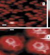
Topographical images of CCVs on a Ca2+-pretreated mica substrate, obtained by soft tapping mode AFM under fluid. (A) A representative field (scale bar = 100 nm) of unprocessed image showing clathrin CCVs mostly between 80 and 100 nm in height (color-scale, right, 0–250 nm), obtained by using a sharpened and clean silicon nitride tip (r ∼3 nm). (B) A bandpass-filtered and contrast-enhanced image area showing a CCV pentagon (left) and a hexagon (right). Scale bar = 20 nm.
FIGURE 2
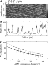
AFM contact mode imaging of CCVs under elastic compression. (A) A portion of a contact-mode AFM image when the imaging force changes over a range of ∼40–300 pN at a rate of ∼0.5 pN per scanline (or per second), obtained by using a relatively blunt silicon nitride AFM tip (r ∼15 nm). The force profile (scale, top left corner), showing a controlled reduction of 100 pN, is plotted (diagonal line) to indicate the AFM compression force at each scanline location (left vertical scale). Grayscale on the right indicates topographic height range to 200 nm. (B) A filtered set of CCV particle profiles (+ signs), tracked along a particular scanline by curve fitting to reduce the effects of noise and lattice struts. (C) The average particle height, estimated for CCVs from scanlines grouped together according to compression force. Solid curve is a linear fit of this force to the inverse of the average height. The dashed line is the average height for the CCV population calculated from the solid line after a geometric correction (Eq. 4).
FIGURE 3
Scanline cross sections of AFM tips determined by blind-tip reconstruction procedures (24). The sharp tip (Tip #1) for tapping-mode images (Fig. 1 A) has a radius of ∼3 nm (dashed circle). The blunt tip (Tip #2) for contact-mode images (Fig. 2 A) is more asymmetric and can be fit to a radius of between 15 nm (_dash_-dotted circle) and 21 nm (dotted circle).
FIGURE 4
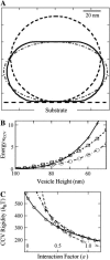
Rigidity analysis of elastic shell models of CCVs (see Materials and Methods, as well as Appendix). (A) Calculated cross sections of CCV shape with axial symmetry perpendicular to the substrate (dashed line, uncompressed CCV at 2_R_0 = 100 nm diameter; solid line, vesicles formed from CMC surfaces, at a deformed height of 70 nm; _dash_-dotted line, oblate spheroidal representation of deformation to the same compressed height of 70 nm). (B) The total bending and surface energy of the CCV shapes shown in panel A in units of bending rigidity, as a function of the vesicle height reduction (+ sign, oblate spheroids; ○ and □, CMC surfaces under different contact interactions with parameter value of ɛ = 0.5 and 1.0, respectively). (C) CCV rigidity calculation, using the measured data in Fig. 2 C and following the force balance relationship given in Eq. 6. The ⋄, +, and ○ signs pertain to height data for compression forces of 75, 175, and 275 pN, representative of the whole data range. The three curves converge near the result _κ_CCV = 285 _k_BT, ɛ = 0.6.
FIGURE 5
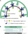
Composite shell rigidity model of a CCV. (A) Cartoon of a 100-nm CCV with average dimensions obtained from EM reconstitutions (–18), highlighting the flexible interlayer coupling inferred here from the measured rigidity of the CCVs. (B) Composite shell of the CCV (total thickness, h ≅ 27 nm), where the clathrin lattice (layer 1: t ≅ 4.5 nm) and vesicle membrane (layer 2) are approximately equal thickness and have similar bending rigidity. The connecting layer (layer 3) provides a partially rigid mechanical coupling whose variation can strongly modulate the rigidity of the CCV.
Similar articles
- Unraveling protein-protein interactions in clathrin assemblies via atomic force spectroscopy.
Jin AJ, Lafer EM, Peng JQ, Smith PD, Nossal R. Jin AJ, et al. Methods. 2013 Mar;59(3):316-27. doi: 10.1016/j.ymeth.2012.12.006. Epub 2012 Dec 25. Methods. 2013. PMID: 23270814 Free PMC article. - Visualizing clathrin-mediated IgE receptor internalization by electron and atomic force microscopy.
Burns AR, Oliver JM, Pfeiffer JR, Wilson BS. Burns AR, et al. Methods Mol Biol. 2008;440:235-45. doi: 10.1007/978-1-59745-178-9_18. Methods Mol Biol. 2008. PMID: 18369950 - Three-dimensional visualization of planta clathrin-coated vesicles at ultrastructural resolution.
Johnson A, Kaufmann WA, Sommer C, Costanzo T, Dahhan DA, Bednarek SY, Friml J. Johnson A, et al. Mol Plant. 2022 Oct 3;15(10):1533-1542. doi: 10.1016/j.molp.2022.09.003. Epub 2022 Sep 7. Mol Plant. 2022. PMID: 36081349 - Snap-shots of clathrin-mediated endocytosis.
Higgins MK, McMahon HT. Higgins MK, et al. Trends Biochem Sci. 2002 May;27(5):257-63. doi: 10.1016/s0968-0004(02)02089-3. Trends Biochem Sci. 2002. PMID: 12076538 Review. - Proteomic analysis of clathrin-coated vesicles.
McPherson PS. McPherson PS. Proteomics. 2010 Nov;10(22):4025-39. doi: 10.1002/pmic.201000253. Proteomics. 2010. PMID: 21080493 Review.
Cited by
- Bending and puncturing the influenza lipid envelope.
Li S, Eghiaian F, Sieben C, Herrmann A, Schaap IAT. Li S, et al. Biophys J. 2011 Feb 2;100(3):637-645. doi: 10.1016/j.bpj.2010.12.3701. Biophys J. 2011. PMID: 21281578 Free PMC article. - Endocytosis against high turgor pressure is made easier by partial coating and freely rotating base.
Ma R, Berro J. Ma R, et al. Biophys J. 2021 May 4;120(9):1625-1640. doi: 10.1016/j.bpj.2021.02.033. Epub 2021 Mar 4. Biophys J. 2021. PMID: 33675763 Free PMC article. - AFM of biological complexes: what can we learn?
Gaczynska M, Osmulski PA. Gaczynska M, et al. Curr Opin Colloid Interface Sci. 2008 Oct;13(5):351-367. doi: 10.1016/j.cocis.2008.01.004. Curr Opin Colloid Interface Sci. 2008. PMID: 19802337 Free PMC article. - Structure of the Plasmodium falciparum circumsporozoite protein, a leading malaria vaccine candidate.
Plassmeyer ML, Reiter K, Shimp RL Jr, Kotova S, Smith PD, Hurt DE, House B, Zou X, Zhang Y, Hickman M, Uchime O, Herrera R, Nguyen V, Glen J, Lebowitz J, Jin AJ, Miller LH, MacDonald NJ, Wu Y, Narum DL. Plassmeyer ML, et al. J Biol Chem. 2009 Sep 25;284(39):26951-63. doi: 10.1074/jbc.M109.013706. Epub 2009 Jul 24. J Biol Chem. 2009. PMID: 19633296 Free PMC article. - Clathrin polymerization exhibits high mechano-geometric sensitivity.
Irajizad E, Walani N, Veatch SL, Liu AP, Agrawal A. Irajizad E, et al. Soft Matter. 2017 Feb 15;13(7):1455-1462. doi: 10.1039/c6sm02623k. Soft Matter. 2017. PMID: 28124714 Free PMC article.
References
- Conner, S. D., and S. L. Schmid. 2003. Regulated portals of entry into the cell. Nature. 422:37–44. - PubMed
- Brodsky, F. M., C. Y. Chen, C. Knuehl, M. C. Towler, and D. E. Wakeham. 2001. Biological basket weaving: formation and function of clathrin-coated vesicles. Annu. Rev. Cell Dev. Biol. 17:517–568. - PubMed
- Marsh, M., and H. T. McMahon. 1999. Cell biology—the structural era of endocytosis. Science. 285:215–220. - PubMed
- Lafer, E. M. 2002. Clathrin-protein interactions. Traffic. 3:513–520. - PubMed
Publication types
MeSH terms
Grants and funding
- R01 NS029051/NS/NINDS NIH HHS/United States
- R56 NS029051/NS/NINDS NIH HHS/United States
- Z01 EB000015-02/Intramural NIH HHS/United States
- NS29051/NS/NINDS NIH HHS/United States
LinkOut - more resources
Full Text Sources
Miscellaneous


