Designing of PLA scaffolds for bone tissue replacement fabricated by ordinary commercial 3D printer - PubMed (original) (raw)
Designing of PLA scaffolds for bone tissue replacement fabricated by ordinary commercial 3D printer
Aleš Gregor et al. J Biol Eng. 2017.
Abstract
Background: The primary objective of Tissue engineering is a regeneration or replacement of tissues or organs damaged by disease, injury, or congenital anomalies. At present, Tissue engineering repairs damaged tissues and organs with artificial supporting structures called scaffolds. These are used for attachment and subsequent growth of appropriate cells. During the cell growth gradual biodegradation of the scaffold occurs and the final product is a new tissue with the desired shape and properties. In recent years, research workplaces are focused on developing scaffold by bio-fabrication techniques to achieve fast, precise and cheap automatic manufacturing of these structures. Most promising techniques seem to be Rapid prototyping due to its high level of precision and controlling. However, this technique is still to solve various issues before it is easily used for scaffold fabrication. In this article we tested printing of clinically applicable scaffolds with use of commercially available devices and materials. Research presented in this article is in general focused on "scaffolding" on a field of bone tissue replacement.
Results: Commercially available 3D printer and Polylactic acid were used to create originally designed and possibly suitable scaffold structures for bone tissue engineering. We tested printing of scaffolds with different geometrical structures. Based on the osteosarcoma cells proliferation experiment and mechanical testing of designed scaffold samples, it will be stated that it is likely not necessary to keep the recommended porosity of the scaffold for bone tissue replacement at about 90%, and it will also be clarified why this fact eliminates mechanical properties issue. Moreover, it is demonstrated that the size of an individual pore could be double the size of the recommended range between 0.2-0.35 mm without affecting the cell proliferation.
Conclusion: Rapid prototyping technique based on Fused deposition modelling was used for the fabrication of designed scaffold structures. All the experiments were performed in order to show how to possibly solve certain limitations and issues that are currently reported by research workplaces on the field of scaffold bio-fabrication. These results should provide new valuable knowledge for further research.
Keywords: 3D printing; Bio-fabrication; Fused deposition modelling; Polylactic acid; Rapid prototyping; Rebel II; Scaffold; Tissue engineering.
Conflict of interest statement
Ethics approval and consent to participate
Not applicable.
Consent for publication
Not applicable.
Competing interests
The authors declare that they have no competing interests.
Publisher’s Note
Springer Nature remains neutral with regard to jurisdictional claims in published maps and institutional affiliations.
Figures
Fig. 1
Scaffold structure ST1. The porosity of ST1 scaffold was expected around 30% and intended diameter of the fibre is 0.35 mm and pore size 0.35 mm
Fig. 2
Scaffold structure ST2. The porosity of ST2 scaffold was expected around 50% and intended diameter of the fibre is 0.35 mm and pore size 0.7 mm
Fig. 3
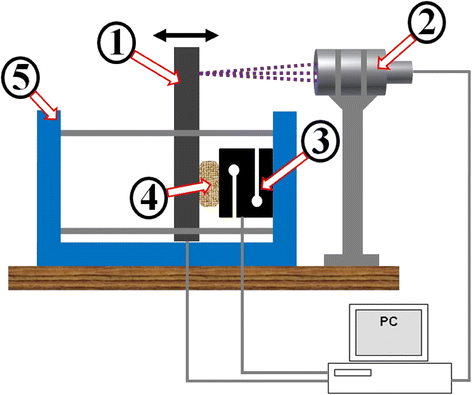
Apparatus served as a mechanism for scaffold’s loading. (1) Mobile cantilever driven by a stepper motor, (2) Confocal probe measures the cantilever displacement resp. scaffold deformation, (3) Force sensor, (4) Scaffold sample, (5) Stiff frame
Fig. 4
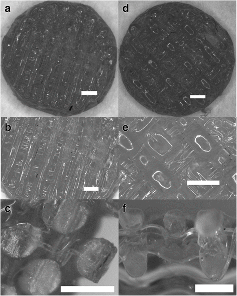
Structure description of printed ST1 and ST2. a Overall view of the scaffold ST1 from the top. b Detail of ST1 view from the top - Printed samples showed satisfactory external and internal geometry. c Sectional view of ST1 fibres. It can be seen that there is no porous or any other structural damages in an internal structure of the fibre. This is an important finding for the evaluation of mechanical properties of the overall scaffold. d Overall view of the scaffold ST2 from the top. e Detail of the view from the top - Printed samples showed satisfactory external and internal geometry. f Sectional view of the scaffold ST2. It can be seen that the precision of layering is of less quality than in the case of ST1 as the gaps between fibres are wider. Bar = 0.5 mm
Fig. 5
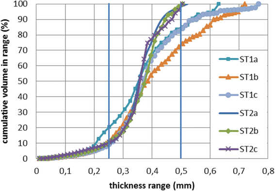
Fibre thickness distribution of ST1 and ST2 measured by micro CT. The thickness of fibres is not absolutely constant. Outlied values are likely residues of printing material (PLA), which is left on the sample when the printhead is moving from one side of the sample to another. A very thin fiber of PLA might be still leaking from the printhead during this movement
Fig. 6
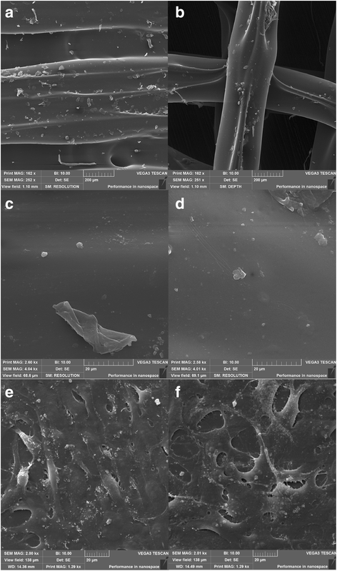
Scanning electron microscopy of ST1 (a, c, e) and ST2 (b, d, f) without and with cells. The surfaces of both scaffolds were smooth with irregular microparticles on the surface. Magnification × 250 (a, b), and × 4000 (c, d). Scanning electron microscopy of ST1 (e) and ST2 (f) seeded with osteosarcoma cells MG-63 after 2 days. MG-63 cells were spread on both scaffolds resembling oval to spindle-shaped morphology typical for osteosarcoma cells and forming small membrane protrusions. Magnification × 2000
Fig. 7
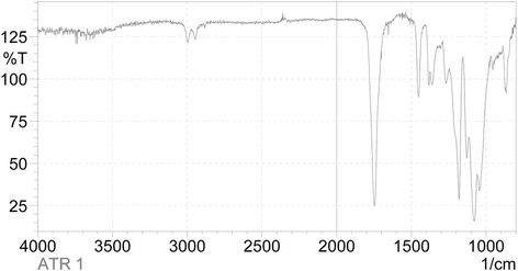
FTIR-IR spectrum of PLA. The CH3 group resonance was detected as peak at 2925 cm−1 and 1274 cm−1. The C = O group resonance was observed at 1756 cm−1, and carboxyl group was observed at 1090 cm−1
Fig. 8
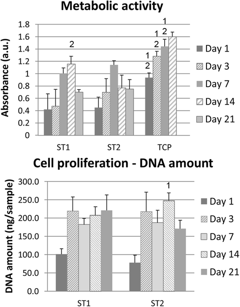
Metabolic activity and dsDNA. Metabolic activity and dsDNA amount are presented as mean of absorbance and standard deviation. Statistical differences compared to ST1 (1) or ST2 (2) groups are shown in graphs above SD values. Metabolic activity was higher on tissue culture polystyrene (TCP) compared to both scaffolds during 14 days; similar results were found for ST1 and ST2 scaffolds, except for higher absorbance on ST1 scaffolds compared to ST2 on day 14. Contrary, higher dsDNA amount was found on ST2 scaffolds than on ST1 scaffold on day 14
Fig. 9
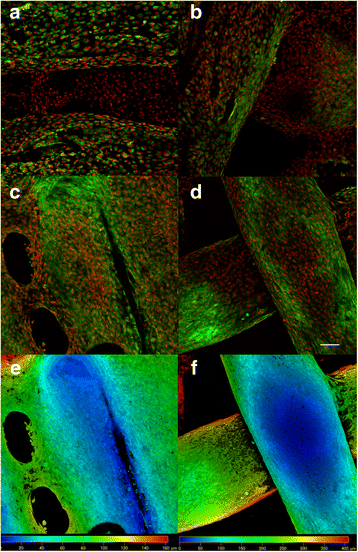
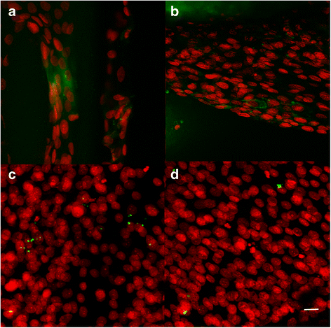
Confocal microscopy of MG-63 cells seeded on ST1 and ST2 - day 3 and day 7. Confocal microscopy of MG-63 cells seeded on ST1 (a, c, e) or ST2 (b, d, f) scaffolds from polylactic acid after a 3-day culture (a, b) or a 7-day culture (c-f). Cells were fixed and cell membranes were stained using DiOC6 (3) (green), cell nuclei were stained with propidium iodide (red). Both maximum projections (a-d) and color coded projections (e, f), which display depth (d) distribution of cells (d = 100 μm in E, d = 400 μm in F) showed fast growth of MG-63 cells on both scaffolds and formation of bridges from cells connecting fibres on ST1 scaffolds on day 7. Objective ×10, Magn. ×2, Bar = 100 μm
Fig. 10
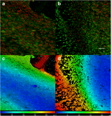
Confocal microscopy of MG-63 cells seeded on ST1 and ST2 - day 14. Confocal microscopy of MG-63 cells seeded on ST1 (a, c) or ST2 (b, d) scaffolds from polylactic acid after a 14-day culture. Cells were fixed and cell membranes were stained using DiOC6 (3) (green), cell nuclei were stained with propidium iodide (red). Both maximum projections (a-b) and color coded projections (c, d), which display depth (d) distribution of cells (d = 180 μm in C, d = 200 μm in D) showed confluent layer of MG-63 cells and formation of bridges from cells connecting fibres on both scaffolds. Objective ×10, magnification ×2, Bar = 50 μm
Fig. 11
Confocal microscopy photomicrographs of ST1 and ST2 seeded with osteosarcoma cells. Confocal microscopy photomicrographs of ST1 (a, c) and ST2 (b, d) scaffolds from polylactic acid seeded with osteosarcoma cells MG-63 after a 7-day and 14-day culture. Immunohistochemical staining using monoclonal antibody against either type I collagen (a, b) or osteocalcin (c, d), followed by secondary antibody conjugated with Alexa Fluor 488® (green) and propidium iodide staining of cell nuclei (red) showed groups of cells producing type I collagen on both scaffolds (a, b) after 7 days, but only rare osteocalcin staining in both scaffolds (c, d) after 14 days. Objective ×10×, magnification ×4, bar = 20 μm
Fig. 12
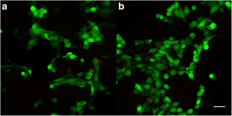
Live/dead staining of osteosarcoma cells seeded on ST1 and ST2 scaffolds. Confocal microscopy photomicrographs of live/dead staining of osteosarcoma cells seeded on ST1 and ST2 scaffolds after a 4-day culture. Live/dead staining of MG-63 seeded scaffolds showed high cell viability on both ST1(a) and ST2(b) scaffolds. Live cells (green), dead cells (red), objective ×10, magnification ×2, bar = 50 μm
Similar articles
- Fabrication of polylactic acid (PLA)-based porous scaffold through the combination of traditional bio-fabrication and 3D printing technology for bone regeneration.
Zhou X, Zhou G, Junka R, Chang N, Anwar A, Wang H, Yu X. Zhou X, et al. Colloids Surf B Biointerfaces. 2021 Jan;197:111420. doi: 10.1016/j.colsurfb.2020.111420. Epub 2020 Oct 18. Colloids Surf B Biointerfaces. 2021. PMID: 33113493 Free PMC article. - On the Fused Deposition Modelling of Personalised Bio-Scaffolds: Materials, Design, and Manufacturing Aspects.
Sousa HC, Ruben RB, Viana JC. Sousa HC, et al. Bioengineering (Basel). 2024 Jul 31;11(8):769. doi: 10.3390/bioengineering11080769. Bioengineering (Basel). 2024. PMID: 39199727 Free PMC article. Review. - Preparation and characterization of PLA/PCL/HA composite scaffolds using indirect 3D printing for bone tissue engineering.
Hassanajili S, Karami-Pour A, Oryan A, Talaei-Khozani T. Hassanajili S, et al. Mater Sci Eng C Mater Biol Appl. 2019 Nov;104:109960. doi: 10.1016/j.msec.2019.109960. Epub 2019 Jul 6. Mater Sci Eng C Mater Biol Appl. 2019. PMID: 31500051 - Cold atmospheric plasma (CAP) surface nanomodified 3D printed polylactic acid (PLA) scaffolds for bone regeneration.
Wang M, Favi P, Cheng X, Golshan NH, Ziemer KS, Keidar M, Webster TJ. Wang M, et al. Acta Biomater. 2016 Dec;46:256-265. doi: 10.1016/j.actbio.2016.09.030. Epub 2016 Sep 22. Acta Biomater. 2016. PMID: 27667017 - A brief review of dispensing-based rapid prototyping techniques in tissue scaffold fabrication: role of modeling on scaffold properties prediction.
Li MG, Tian XY, Chen XB. Li MG, et al. Biofabrication. 2009 Sep;1(3):032001. doi: 10.1088/1758-5082/1/3/032001. Epub 2009 Aug 21. Biofabrication. 2009. PMID: 20811104 Review.
Cited by
- The Development of Poly(lactic acid) (PLA)-Based Blends and Modification Strategies: Methods of Improving Key Properties towards Technical Applications-Review.
Andrzejewski J, Das S, Lipik V, Mohanty AK, Misra M, You X, Tan LP, Chang BP. Andrzejewski J, et al. Materials (Basel). 2024 Sep 17;17(18):4556. doi: 10.3390/ma17184556. Materials (Basel). 2024. PMID: 39336298 Free PMC article. Review. - Epigallocatechin Gallate-Modified Gelatins with Different Compositions Alter the Quality of Regenerated Bones.
Hara E, Honda Y, Suzuki O, Tanaka T, Matsumoto N. Hara E, et al. Int J Mol Sci. 2018 Oct 19;19(10):3232. doi: 10.3390/ijms19103232. Int J Mol Sci. 2018. PMID: 30347668 Free PMC article. - Note on the use of different approaches to determine the pore sizes of tissue engineering scaffolds: what do we measure?
Bartoš M, Suchý T, Foltán R. Bartoš M, et al. Biomed Eng Online. 2018 Aug 17;17(1):110. doi: 10.1186/s12938-018-0543-z. Biomed Eng Online. 2018. PMID: 30119672 Free PMC article. - Osteogenesis of Multipotent Progenitor Cells using the Epigallocatechin Gallate-Modified Gelatin Sponge Scaffold in the Rat Congenital Cleft-Jaw Model.
Sasayama S, Hara T, Tanaka T, Honda Y, Baba S. Sasayama S, et al. Int J Mol Sci. 2018 Nov 29;19(12):3803. doi: 10.3390/ijms19123803. Int J Mol Sci. 2018. PMID: 30501071 Free PMC article. - Synthetic Biodegradable Aliphatic Polyester Nanocomposites Reinforced with Nanohydroxyapatite and/or Graphene Oxide for Bone Tissue Engineering Applications.
Li Y, Liao C, Tjong SC. Li Y, et al. Nanomaterials (Basel). 2019 Apr 10;9(4):590. doi: 10.3390/nano9040590. Nanomaterials (Basel). 2019. PMID: 30974820 Free PMC article. Review.
References
- Ha TLB, Quan TM, Vu DN, Si DM. Naturally derived biomaterials: preparation and application. Regenerative Medicine and Tissue Engineering. 2013. doi:10.5772/55668.
LinkOut - more resources
Full Text Sources
Other Literature Sources


