Graflex Super Graphic Conversion (original) (raw)
The Super Speed was a complete re-design of the Graphic series. It boasted an extruded aluminum frame, a rotating back, a cammed rangefinder, and a built-in solenoid lens release.
Some years back, during one of those lost weekends when I didn’t have anything better to do, I made a rather interesting discovery: When you strip out all the rangefinder and solenoid hardware - what remains is a field camera that weighs under four and one half pounds! And not a bad one at that. With front swings and tilts and a drop bed, it's almost as good as a real $2000.00 field camera. All it would need, to make it appeal to an F-64 type nature photographer (like myself), would be a tilting back and wide angle capability.
So, during another equally lost weekend, I tore into it and came up with the following modifications:
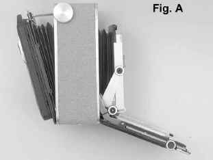
1. Fig. A Note the increased angle of the bed drop. To accomplish this, you simply re-position the slider brackets on the inside of the frame and round-off the edge of the frame to allow the bed to pivot more.
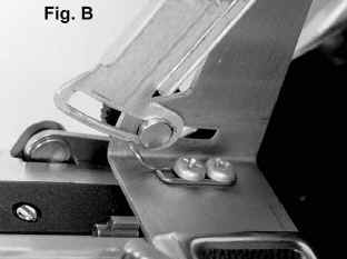
2. Fig. B With the bed dropping more, the front standard will have to tilt more. This is easily accomplished by reversing the front standard supports and installing stops as shown, to facilitate squaring up the camera. While you have the supports off, you can take that opportunity to lengthen the grooves and slots accordingly to increase the front rise and fall.
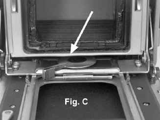
3. Fig. C By cutting off the small housing that holds the solenoid and folding up the aluminum retainer as shown, you can allow the front to drop an added half inch.
If you don't plan on using the 65mm lens, you can eliminate the preceding steps and concentrate on the back tilt. (To use the Schneider F8-65mm lens you would also have to make a recessed contraption like the one shown in Fig.G.)
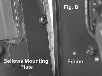
4. Fig. D If you turn the back about 45 degrees and remove the pressure plate, you will notice the small spring clips that hold the bellows in place. Remove all the clips and the bellows and front standard can be separated from the camera. At this point, you will notice that in order for the back to tilt you will need to remove the bellows mounting plate and trim off about one eighth of an inch from the sides of this plate, which would otherwise grip the frame.
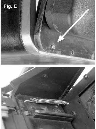
5. Fig. E The hinge is accomplished with finishing nails. The holes through the back are oversize and heavily countersunk to allow the back to pivot. The nails simply press fit into the edge of the frame. To keep this whole thing stable, install a small spring as shown, on each side.
6. Fig. F There are two methods I have used to lock the tilt in place. The best, of course, is the rack and pinion. I won't go into the details here...suffice to say that it requires a 35mm bellows adapter that you are willing to trash and a milling machine to adapt it to this application. The easiest (and just as good) is a simple locking slide mechanism like the one shown here. The rod that runs the width of the camera is hollow and has a pin between the two slides so that one knob will tighten both slides. There is no reason why a single slide in the center of the camera couldn’t be used...with the knob on the top of the camera.
Revised: November 26, 2003. Copyright � 1998 Bruce Wehman. All rights reserved. This means you may NOT copy and re-use the text or the pictures in ANY other internet or printed publication of ANY kind. Information in this document is subject to change without notice. Other products and companies referred to herein are trademarks or registered trademarks of their respective companies or mark holders.