HP CPU and Programming (original) (raw)
The hardware technology used in HP calculators improved steadily over the years, moving from multichip to single chip designs with greater speeds and capabilities. However, the programming model remained much the same from the HP-35 though the HP-30E/C series. This document provides a brief description of the programming style of these early models. The HP-01, HP-41C and the Saturn processors were similar. Their differences are highlighted below.
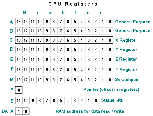
56-bit Registers
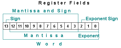
The HP calculator CPUs were optimized for floating point numbers. Each main register consisted of 14 of 4 bits each (56 bits per register) This allowed each register to hold a 10 digit mantissa, a 2 digit exponent and signs for the mantissa and exponent. Each digit or sign occupied 4 bits. This is commonly referred to as Binary Coded Decimal (BCD) encoding. The 56-bit registers were:
- A & B: General purpose registers for math and scratchpad use.
- C: Like A and B but also dedicated to memory reads and writes and transfers to M. The C register also contained the value displayed in the X register.
- D, E, F: These registers held the user stack levels Y, Z, and T. These registers were accessed by rotating them down (in just the same operation as a R↓ at the user level) or by using STACK -> reg style commands.
- M: A scratchpad register which only supported transfers to and from the C register. No math etc.
Additional Registers
- P: a 4-bit "pointer" register used with the P and WP field selects (below) allowed subsets of registers to be accessed. Note that this pointer was an offset into the register(s) rather than a pointer to memory.
- DATA: Held the address that register C could be read from or written to. (This was actually part of the data storage circuit in the classic models.)
- S0-S11: 12 bits of programmable status.
Field Selects
Many operations were controlled by a field select option. This allowed portions of each register to be accessed independently. The field select codes where:
| M | Mantissa |
|---|---|
| MS | Mantissa and Sign |
| X | Exponent |
| XS | Exponent Sign |
| S | (Mantissa) Sign |
| P | Pointer (The nibble indicated by the P register) |
| W | Word (the entire register) |
| WP | Word up to and including nibble indicated by P register from right to left. For example, if P=3, WP would refer to nibbles 0, 1, 2, and 3. |
The sign nibbles are set to 0 if positive and 9 if negative.
The Saturn processors added field selects for Byte and Address.
Addressing
The classic models used 8-bit instruction addresses plus ROM select instructions to activate the appropriate 256-word ROM. The 20 series used 12-bit addresses. The classics had a subroutine stack depth of one versus 2 for the 20 series.
The user stack was contained in on-chip memory, however, multiple user memories as found on the HP-45, financial memories and program memory all required additional data storage. To access registers in off-chip memory, the CPU first supplied the address to the storage chip using C-> DATA ADDRESS and then read or wrote the data at that address. 20 series machines added operations that allowed a read or write to off-chip memory with a single instruction.
Instructions
In general, registers (or portions) could be cleared, copied, exchanged, incremented or decremented. In addition, registers could be shifted left or right and tested. Portions of registers to act on were indicated by enclosing the field select code in brackets after the instruction. Each instruction occupied 10 bits.
The following symbols are used in the Instructions below:
| fs | field select (one of the codes above: M, MS, etc.) |
|---|---|
| gr | general purpose register (A, B, or C) |
| lbl | a label |
| bit | a value of 0 or 1 |
| digit | a value between 0 and 9 |
| stat | a status register bit number (0 - 11) |
| ptr | a pointer value (0-13) |
| rom | a rom number (max depends on model) |
Known Instructions:
| CLEAR REGISTERS | Set all 56-bit registers to zero. |
|---|---|
| 0 -> _gr_[_fs_] | Set the selected part of gr register to zero. |
| A -> B[_fs_] B -> C[_fs_] C -> A[_fs_] M -> C C -> M | Copy the selected part of the register on the left to the register on the right. Examples: B - > C[X]: copy the exponent part of B to the exponent part of C. A -> B[WP]: copy A to B from the right most nibble up through the nibble indicated by the P register. |
| A EXCHANGE B[_fs_] A EXCHANGE C[_fs_] C EXCHANGE B[_fs_] C EXCHANGE M | Exchange the selected portions of the two registers. Note that transfers to/from M are always full word transfers. |
| A + B -> A[_fs_] A + C -> A[_fs_] A + C -> C[_fs_] C + C -> C[_fs_] A - B -> A[_fs_] A - C -> C[_fs_] A - C -> A[_fs_] | Perform math on the selected portions of the indicated registers |
| A + 1 -> A[_fs_] | Increment the selected portion |
| C + 1 -> C[_fs_] | |
| A - 1 -> A[_fs_] | Decrement the selected portion |
| C - 1 -> C[_fs_] | |
| -C -> C[_fs_] | Negate C (tens complement) |
| -C -1 -> C[_fs_] | Negate and decrement C (nines complement) |
| SHIFT RIGHT _gr_[_fs_] | Shift selected portion of gr right |
| SHIFT LEFT A[_fs_] | Shift selected portion of A left |
| IF B[_fs_] = 0 IF C[_fs_] = 0 IF A >= C[_fs_] IF A >= B[_fs_] IF A[_fs_] >= 1 IF B[_fs_] >= 1 | Test for selected part of of register (Follow these with THEN GO TO) |
| THEN GO TO lbl | Go to label lbl if true (must follow one of the IFs above) |
| GO TO lbl | Unconditional go to |
| IF NO CARRY GO TO lbl | Go to label if carry bit is not set |
| CLEAR STATUS | Clear all 12 status bits |
| bit -> S_stat_ | Set Status bit stat to bit (Example: 1 -> S10) |
| IF S_stat_ = 0 | Test if status bit equal to 0 (follow with THEN GO TO) |
| IF S_stat_ # 1 | Test if status bit not equal to 1 (same as above test) |
| ptr -> P | Set P register to ptr (_ptr_th nibble for P field select or through ptr for WP) |
| P + 1 -> P P -1 -> P | Increment and decrement P |
| IF P # ptr | Test if P not equal to ptr (follow with THEN) |
| C -> STACK | Push C onto the stack (E->F, D->E, C->D) always whole word |
| STACK -> A | Pop stack into A (D->A, E->D, F->E) always whole word |
| ROTATE DOWN | Move D to C, E to D, F to E and the original C to F (just like pressing the R↓ key.) |
| JSB lbl | Jump to Subroutine labeled xyz (one level of subroutines on the Classics, 2 on 20 series.) |
| RETURN | Return to the instruction after the JSB. |
| LOAD CONSTANT digit | digit -> C at the Pth nibble. P is then decremented so multiple digits can be loaded easily. |
| SELECT ROM rom | Select ROM #rom for addressing. |
| KEYS -> ROM ADDRESS | Jump to the offset of the current keycode in the currently selected ROM. |
| DISPLAY OFF | Turn the display off |
| DISPLAY TOGGLE | Toggle the LED display on/off. |
| C -> DATA ADDRESS | Set current data address to value in C* Precursor to reading or writing off-chip memory. |
| DATA -> C | Read data in to C register* |
| C -> DATA | Write data from C register* |
| NO OPERATION | Does nothing. |
* For example, to write the value in B into the address indicated by C, the program could do:
C -> DATA ADDRESS
B -> C[W]
C -> DATA
George Weigt has provided an opcode map in the articles forum.
Programming Example - The HP-45
Eric Smith was able to piece together the entire HP-45 firmware listing by reading patent disclosures. In addition to reading the firmware, you can run and step through it on this HP-45 Microcode simulator.
Programming Example - The HP-65
This code segment normalizes numbers as keyed into the user. The user input in the A and B registers is normalized into the C register. This code segment is from the HP Journal (used with permission.) Sign nibbles are 0 if positive, 9 if negative.
HP-01
The HP-01 was similar to the classic series except that its registers were only 48 bits wide.
The HP-41C
The HP-41C added additional capabilities such as:
- A more general I/O system (Select a peripheral, then read or write register C from/to it.) RAM, the display, the card reader, wand etc. were accessed this way.
- Another scratchpad register (N) which, like the M register, could only be used to move data to/from C.
- An 8-bit register G which made the CPU more useful for character/byte-oriented information. This register's contents could be moved to/from any portion of the C register.
- A second pointer register Q. (P or Q was selected for future field select operations with a separate command.)
- Hex and decimal math modes.
- T register was used to generate tones.
- Subroutine stack expanded to four registers.
- Program addresses expanded to 16 bits.
- Status bit register expanded to 14 bits.
- Additional field selects: Key Buffer and Address.
Saturn
Saturn processors expanded on the HP-41C processor by widening the main registers to 64 bits, widening program addresses to 20 bits, expanding subroutines to 6 registers (plus two for the interrupt system.) and adding:
- Two data pointer registers.
- More main registers - 4 general purpose and 5 scratchpad.
- New select field: Byte
- Interrupt support
- Many additional instructions including easier off-chip data access, improved constant loading, more return instructions etc.
Additional information may be found on the Saturn page.
 Go to the HP-45 Microcode Simulator Go to classic series technology Go to 20 series technology Go to 30 series technology Go to the main exhibit hall