Multiply-Add - Multiply-add combined operation - Simulink (original) (raw)
Multiply-add combined operation

Libraries:
HDL Coder / HDL Operations
Description
The Multiply-Add block computes the product of the first two inputs, a and b, and adds the result to the third input, c. The inputs can be vectors or scalars.
The multiplication operation is full precision, regardless of the output type. TheInteger rounding mode, Output data type, and Saturate on integer overflow settings apply only to the addition operation. The addition operation uses the accumulator data type setting asInherit : Inherit via internal rule by default.
Use the Multiply-Add block to map a combined multiply-add or a multiply-subtract operation to a DSP unit in your target hardware. You can select the setting in the Block Parameters dialog box for the Multiply-Add block.
To map to a DSP unit, specify the SynthesisTool property for your model. When you generate HDL code for your model, HDL Coder™ configures the multiply-add operation so that your synthesis tool can map to a DSP unit.
Note
Some DSP units do not have the multiply-add capability. To see if your hardware has the multiply-add capability, refer to the documentation for the hardware.
Limitations
The Multiply-Add block accepts and outputs signals of numeric data type that Simulink® supports, including fixed-point data types.
You can use matrix data types with the Multiply-Add block. When you use these types, the port dimensions of the inputs a andb must match. For example, in MATLAB®, you can perform these matrix operations:
a = [1 2; 3 4]; b = [5; 6]; c = 7;
c + (a.*b)
However, when you perform this multiplication in the Simulink environment, you see an error: Error in port widths or dimensions.
See Data Types Supported by Simulink.
Ports
Input
Input signal to be multiplied with input to Portb.
Data Types: single | double | int8 | int16 | int32 | uint8 | uint16 | uint32 | fixed point
Input signal to be multiplied with input to Porta.
Data Types: single | double | int8 | int16 | int32 | uint8 | uint16 | uint32 | fixed point
Input signal that gets added or subtracted to the product ofa and b depending on setting.
Data Types: single | double | int8 | int16 | int32 | uint8 | uint16 | uint32 | fixed point
Output
Output data from the multiply-add operation.
Data Types: single | double | int8 | int16 | int32 | uint8 | uint16 | uint32 | fixed point
Parameters
Specify the function to perform a combined multiply and add or a multiply and subtract operation.
Programmatic Use
| **Parameter:**Function | |
|---|---|
| Type: string scalar | character vector | |
| Value:"c+(a.*b)" |"c-(a.*b)" | "(a.*b)-c" |
| Default: 'c+(a.*b)' |
Specify the output data type. This parameter sets the output data type for the addition operation. You can set the output data type to:
- A rule that inherits a data type, for example,
Inherit: Same as input - An expression that evaluates to a valid data type, for example,
fixdt([],16,0)
Click the Show data type assistant button to display the Data Type Assistant dialog box, which helps you to set the Output data type parameter.
For more information, see Control Data Types of Signals.
Specify the rounding mode for fixed-point operations as either:
Ceiling
Rounds positive and negative numbers toward positive infinity. Equivalent to the MATLABceil function.
Convergent
Rounds number to the nearest representable value. If a tie occurs, rounds to the nearest even integer. Equivalent to the Fixed-Point Designer™convergent function.
Floor
Rounds positive and negative numbers toward negative infinity. Equivalent to the MATLABfloor function.
Nearest
Rounds number to the nearest representable value. If a tie occurs, rounds toward positive infinity. Equivalent to the Fixed-Point Designernearest function.
Round
Rounds number to the nearest representable value. If a tie occurs, rounds positive numbers toward positive infinity and rounds negative numbers toward negative infinity. Equivalent to the Fixed-Point Designerround function.
Simplest
Chooses between rounding toward floor and rounding toward zero to generate rounding code that is as efficient as possible.
Zero
Rounds number toward zero. Equivalent to the MATLABfix function.
Programmatic Use
| **Parameter:**RndMeth | |||||
|---|---|---|---|---|---|
| Type: string scalar | character vector | |||||
| Value:"Ceiling" |"Convergent" | "Floor" | "Nearest" | "Round" | "Simplest" | "Zero" |
| Default: 'Floor' |
See Also
For more information, see Rounding Modes.
 On
On
Overflows saturate to either the minimum or maximum value that the data type can represent.
For example, an overflow associated with a signed 8-bit integer can saturate to -128 or 127.
 Off
Off
Overflows wrap to the appropriate value that the data type can represent.
For example, the number 130 does not fit in a signed 8-bit integer and wraps to -126.
Tips
- Consider selecting this check box when your model has a possible overflow and you want explicit saturation protection in the generated code.
- Consider clearing this check box when you want to optimize efficiency of your generated code.
Clearing this check box also helps you to avoid overspecifying how a block handles out-of-range signals. For more information, see Troubleshoot Signal Range Errors. - When you select this check box, saturation applies to every internal operation on the block, not just the output or result.
- In general, the code generation process can detect when overflow is not possible. In this case, the code generator does not produce saturation code.
Programmatic Use
| **Parameter:**SaturateOnIntegerOverflow |
|---|
| Type: string scalar | character vector |
| Value: "off" | "on" |
| Default: 'off' |
Algorithms
If you have fixed-point inputs to a Multiply-Add block, you can set the PipelineDepth for the block. For floating-point inputs, HDL Coder ignores the PipelineDepth parameter and does not insert pipeline registers.
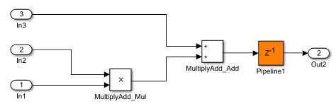
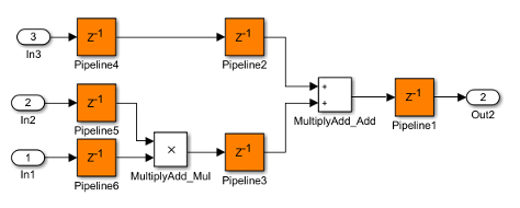
The following diagrams show different configurations of pipeline registers for different synthesis tools and PipelineDepth settings. When you specify the PipelineDepth setting, HDL Coder inserts pipeline registers so that the configuration maps efficiently to DSP units.
Altera Hardware with PipelineDepth = 1
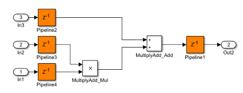
Altera Hardware with PipelineDepth = 2
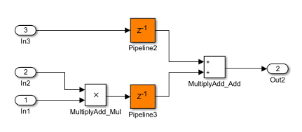
Xilinx Hardware with PipelineDepth = 1
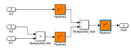
Xilinx Hardware with PipelineDepth = 2
Xilinx Hardware with PipelineDepth = 3
Extended Capabilities
HDL Coder provides additional configuration options that affect HDL implementation and synthesized logic.
HDL Architecture
This block has one default HDL architecture.
HDL Block Properties
| PipelineDepth | Number of pipeline stages. The default isauto which means that the code generator determines the number of pipeline stages based on your synthesis tool. For adaptive pipelines to be inserted, when PipelineDepth is set to auto, you must specify the synthesis tool and enter a target frequency value greater than zero.You can enter an integer between 0 and 3. For Altera® hardware targets, the maximum pipeline depth is 2. |
|---|
| General | |
|---|---|
| HandleDenormals | Specify whether you want HDL Coder to insert additional logic to handle denormal numbers in your design. Denormal numbers are numbers that have magnitudes less than the smallest floating-point number that can be represented without leading zeros in the mantissa. The default isinherit. See also HandleDenormals. |
| LatencyStrategy | Specify whether to map the blocks in your design toinherit, Max, Min, or Zero for the floating-point operator. The default isinherit. See also LatencyStrategy. |
| MantissaMultiplyStrategy | Specify how to implement the mantissa multiplication operation during code generation. By using different settings, you can control the DSP usage on the target FPGA device. The default is inherit. See also MantissaMultiplyStrategy. |
Complex Data Support
This block supports code generation for complex signals.
Restrictions
- When the block has floating-point inputs, HDL Coder ignores the PipelineDepth parameter and does not insert pipeline registers.
- If the block is in a feedback loop and you do not have sufficient delays at the block output, the code generator reduces thePipelineDepth to prevent delay balancing failure. For sufficient delays, add Delay blocks at the output of theMultiply-Add block.
- To map the combined multiply-add operation to a DSP unit, the width of the third input c has to be less than 64 bits for Altera and 48 bits for Xilinx® respectively.
- The subtraction operation in the Function setting
(a.*b)-cdoes not map to a DSP unit in Altera FPGA libraries.
Version History
Introduced in R2015b