Generate HDL Code for IIR Filter - MATLAB & Simulink (original) (raw)
This example shows how to design and generate HDL code for a DC blocking filter in MATLAB®.
A DC blocking filter is a high-pass filter with a very low frequency transition frequency that typically achieves the highpass response by subtracting a lowpass version of the input from the input, leaving just the portions of the signal above DC. This application is a natural fit for infinite impulse-response (IIR) filters since they are able to provide a steep transition bandwidth with fewer resources than a more common finite impulse response (FIR) filter. A drawback of an IIR filter is that stability of the filter is not guaranteed, so generally a second-order section (SOS), also known as a biquad filter, design is used. Biquad filters can guarantee stability even after fixed-point quantization.
Filter Design
Start with a common specification of passband ripple of 0.1 dB and a stopband attenuation of 60 dB. Using an elliptical filter design method provides steeper roll-off transition bandwidth characteristics than Butterworth or Chebyshev filter designs and often allows the lowest order for a given frequency response. The downside to this type of filter is that the poles and zeros are often very close to the unit circle and the stability of a quantized filter can sometimes be challenging. When you design SOS or biquad filters, use a design method that returns zeros, poles, and gain,  , rather than the multiplied-out transfer function,
  , since the transfer function polynomial can have numerical instability. The poles in the pole-zero plot (represented by x values) are very near but still inside the unit circle, making the double-precision filter stable.
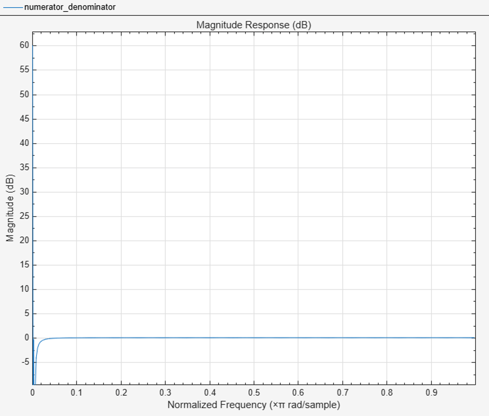
filterOrder = 6; normalizedBandwidth = 0.001; passbandRipple = 0.1; stopbandAtten = 60; [z,p,k] = ellip(filterOrder,passbandRipple,stopbandAtten,normalizedBandwidth); [sos,g] = zp2sos(z,p,k); numerator = sos(:,1:3); denominator = sos(:,4:6); f1 = filterAnalyzer(numerator,denominator);
f2 = filterAnalyzer(numerator,denominator,Analysis="polezero");
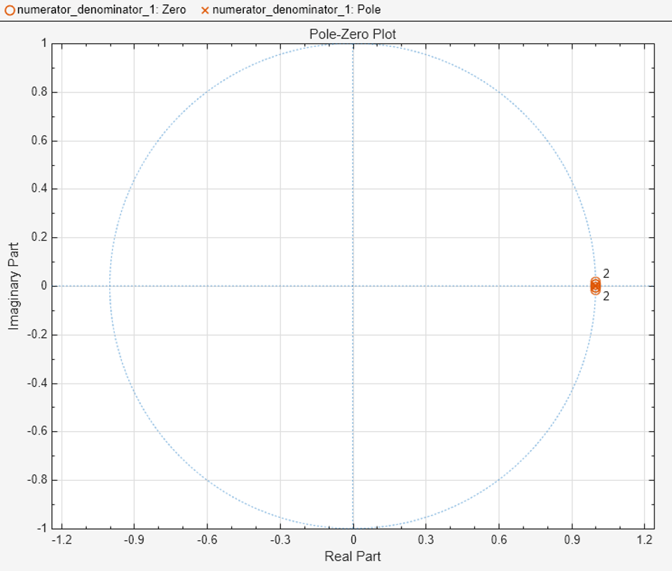
To zoom in on the poles, use this command:
zoom(f2,"xy",[0.98 1.02 -0.03 0.03])
Quantizing the numerator and denominator coefficient independently allows for better results, so this code separates the numerator and denominator before quantization. This design has 12-bit input and targets a typical DSP element in an FPGA, so the example uses 20 bits for numerator and denominator coefficients. The pole-zero plot shows the quantized fixed-point numerator and denominator coefficients after they are converted back to double data type for analysis.
scaleValues = g; num_q = fi(numerator,1,20); den_q = fi(denominator,1,20); f3 = filterAnalyzer(double(num_q),double(den_q),Analysis="polezero");
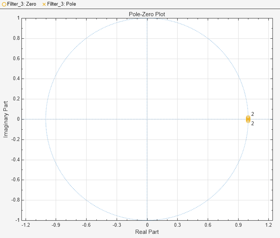
To zoom in on the poles, use this command:
zoom(f3,"xy",[0.98 1.02 -0.03 0.03])
Generate HDL Code
Write a function that creates, configures, and calls the dsphdl.BiquadFilter System object™, and then subtracts the filter output from the input signal. This function copies the constant filter coefficient values calculated earlier in the example. You can generate HDL code from this function.
function [dataOut,validOut] = hdlDCBlocker(dataIn,validIn)
%hdlDCBlocker
% Process one sample of data using the dsphdl.BiquadFilter System object
% and subtract the filter output from the input signal.
%
% dataIn is a fixed-point scalar value.
% validIn is a Boolean scalar value.
%
% You can generate HDL code from this function.
persistent dcb
persistent match_delay
if isempty(dcb)
% created with :
% filterOrder = 6;
% normalizedBandwidth = 0.001;
% passbandRipple = 0.1;
% stopbandAtten = 60;
% [z,p,k] = ellip(filterOrder,passbandRipple,stopbandAtten,normalizedBandwidth);
% [sos,g] = zp2sos(z,p,k);
sos = [ 1 -1.999722603795258 1 1 -1.996966921747073 0.996970384830556
1 -1.999958253432398 1 1 -1.998230761471139 0.998238515958742
1 -1.999975040895448 1 1 -1.999468743777808 0.999479603410253 ];
g = 9.974265048748800e-04;
    num = sos(:,1:3);
    den = sos(:,4:6);
    dcb = dsphdl.BiquadFilter(Numerator = num, ...
        Denominator = den, ...
        ScaleValues = g  , ...
        NumeratorDataType = "Custom", ...
        DenominatorDataType = "Custom", ...
        ScaleValuesDataType = "Custom", ...
        AccumulatorDataType = "Custom", ...
        OutputDataType = "Custom", ...
        CustomNumeratorDataType = numerictype(1,20,18), ...
        CustomDenominatorDataType = numerictype(1,20,18), ...
        CustomScaleValuesDataType = numerictype(1,20,19), ...
        CustomAccumulatorDataType = numerictype(1,60,40), ...
        CustomOutputDataType = numerictype(1,60,40) ...
        );
    match_delay = dsp.Delay(28);
end
[filtOut,validOut] = dcb(dataIn,validIn);
dataOut = match_delay(dataIn) - filtOut;
end
% Copyright 2024 The MathWorks, Inc.
Write a testbench that generates an input signal and calls your filter function. This function defines the input and output data types for your generated HDL code.
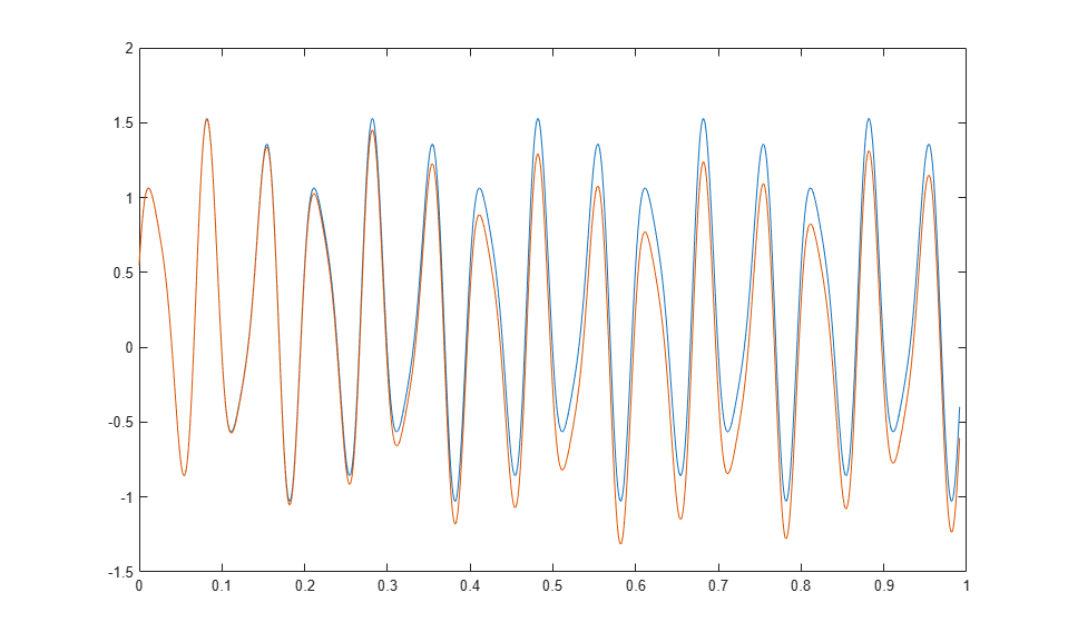
function hdlDCBlocker_TB % Generates a sine wave and DC offset as input to a DC blocker filter. % t = (0:0.0003:1)'; x = sin(30pit) + 0.3cos(50pi*t) + 0.25; numIn = size(t,1);
dataIn = fi(x,1,22,18); validIn = ones(numIn,1,'logical'); dataOut = fi(zeros(numIn,1),1,40,36); validOut = false(numIn,1);
for k = 1:numIn [dataOut(k),validOut(k)] = hdlDCBlocker(dataIn(k), validIn(k)); end
numOut = length(validOut(validOut)); plot(t(1:numOut),dataIn(1:numOut)) hold on; plot(t(1:numOut),dataOut(validOut)) end
% Copyright 2024 The MathWorks, Inc.
To generate HDL code and an HDL simulator testbench for this function, create a coder configuration object and set its properties. For more information, see coder.HdlConfig (HDL Coder).
hdlcfg = coder.config('hdl'); hdlcfg.DesignFunctionName = 'hdlDCBlocker'; hdlcfg.TestBenchName = 'hdlDCBlocker_TB'; hdlcfg.GenerateHDLTestBench = true;
Call the code generation function with your hdlcfg object. When the coder runs the testbench file to generate inputs and expected outputs for the HDL testbench, it displays a plot of the filter input and output.
Begin MATLAB to HDL Code Generation...
Working on DUT: hdlDCBlocker.
Using TestBench: hdlDCBlocker_TB.
Begin VHDL Code Generation
Working on hdlDCBlocker/dsphdl.BiquadFilter/BiquadDF2Section1 as BiquadDF2Section1.vhd.
Working on hdlDCBlocker/dsphdl.BiquadFilter/BiquadDF2Section2 as BiquadDF2Section2.vhd.
Working on hdlDCBlocker/dsphdl.BiquadFilter/BiquadDF2Section3 as BiquadDF2Section3.vhd.
Working on hdlDCBlocker/dsphdl.BiquadFilter as dsphdl_BiquadFilter.vhd.
Working on hdlDCBlocker/SimpleDualPortRAM_generic as SimpleDualPortRAM_generic.vhd.
Working on hdlDCBlocker as hdlDCBlocker.vhd.
Generating Resource Utilization Report resource_report.html.
Generating Optimization report
To rerun codegen evaluate the following commands...
cgi = load('/tmp/Bdoc25a_2864802_1487924/tp39bf8da4/dsphdl-ex35547570/codegen/hdlDCBlocker/hdlsrc/codegen_info.mat'); inVals = cgi.CodeGenInfo.inVals; cfg = cgi.CodeGenInfo.codegenSettings; codegen -config cfg -args inVals -report
Begin TestBench generation.
Code generation successful.
Collecting data...
Begin HDL test bench file generation with logged samples
Generating test bench data file: /tmp/Bdoc25a_2864802_1487924/tp39bf8da4/dsphdl-ex35547570/codegen/hdlDCBlocker/hdlsrc/dataIn.dat.
Generating test bench data file: /tmp/Bdoc25a_2864802_1487924/tp39bf8da4/dsphdl-ex35547570/codegen/hdlDCBlocker/hdlsrc/dataOut_expected.dat.
Generating test bench data file: /tmp/Bdoc25a_2864802_1487924/tp39bf8da4/dsphdl-ex35547570/codegen/hdlDCBlocker/hdlsrc/validOut_expected.dat.
Working on hdlDCBlocker_tb as /tmp/Bdoc25a_2864802_1487924/tp39bf8da4/dsphdl-ex35547570/codegen/hdlDCBlocker/hdlsrc/hdlDCBlocker_tb.vhd.
Generating package file /tmp/Bdoc25a_2864802_1487924/tp39bf8da4/dsphdl-ex35547570/codegen/hdlDCBlocker/hdlsrc/hdlDCBlocker_tb_pkg.vhd.
Generating HDL Conformance Report hdlDCBlocker_hdl_conformance_report.html.
HDL Conformance check complete with 0 errors, 0 warnings, and 0 messages.
Code generation successful: To view the report, open('codegen/hdlDCBlocker/hdlsrc/html/report.mldatx')