fiber connectors (original) (raw)
Definition: connectors used as terminations of optical fiber cables
Alternative terms: fiber-optic connectors, optical fiber connectors
Category:  fiber optics and waveguides
- optics
- fiber optics
* fibers
* fiber connectors
* fiber-optic adapters
* fiber couplers
* fiber-optic pump combiners
* fiber bundles
* fiber endface inspection
* cleaving of fibers
* fiber cleavers
* fiber joints
* fiber splices
* fiber Bragg gratings
* fiber cables
* fiber coatings
* fiber strippers
* fiber recoaters
* fiber coils
* fiber collimators
* fiber launch systems
* fiber lenses
* fiber loop mirrors
* fiber patch panels
* fiber shuffles
* fiber-optic attenuators
* fiber-optic plates
* fiber-optic tapers
* (more topics)
- fiber optics
Related: fiber cablesfiber-optic adaptersfiber patch panelsfiber shufflesfiber opticsfiber to the homefiber collimatorsfiber endface inspectioncleaning of fiber ends
Page views in 12 months: 1881
DOI: 10.61835/en8 Cite the article: BibTex BibLaTex plain textHTML Link to this page! LinkedIn
Content quality and neutrality are maintained according to our editorial policy.
📦 For purchasing fiber connectors, use the RP Photonics Buyer's Guide — an expert-curated directory for finding all relevant suppliers, which also offers advanced purchasing assistance.
Contents
Key questions:
- What is the typical process of fitting a fiber connector plug to a fiber?
- What are the most common types of single-fiber and multi-fiber connectors?
- What are the key characteristics relevant for the selection of fiber connectors?
- Why is it important to measure insertion loss and return loss in sensitive cases?
What are Fiber Connectors?
Fiber connectors are often used as the terminations of optical fiber cables to provide non-permanent connections between fiber-coupled devices (a kind of removable fiber joints). They are used in a similar manner as electrical connectors. For example, they can be plugged into receptables on front panels of various devices, or into fiber patch panels containing many connector adapters.
Typically, a connector assembly comprises an adapter and two connector plugs, where one fiber is inserted into every connector plug. The process of fitting a connector plug to a fiber is more delicate than for most electrical connections:

Figure 1: A fiber connector at the end of a fiber cable. The photograph has been kindly provided by NKT Photonics.
- First, a clean fiber end must be prepared, usually with a fiber cleaver. It must be ensured that the orientation of the fiber interface is correct, e.g. perpendicular to the fiber axis or with some defined angle to it (e.g. 8°). This might be checked with various types of fiber endface inspection.
- Then the fiber end needs to be carefully inserted into the connector plug. Its position must be precisely correct, and the fiber end should not be damaged during that process. Depending on the type of fiber connector, a detailed procedure must be followed, which normally includes the proper preparation and cleaning of the plug and some polishing of the fiber tip. Most connectors require a type of epoxy or other optical adhesive to fix the fiber.
- In sensitive cases, it may be necessary to measure the insertion loss and/or return loss (see below), as it may otherwise be more cumbersome to localize a fault later on.
These termination assembly operations are often performed in factories, but with suitable equipment they can also be done in the field, preferably in a reasonably clean environment. A typical workflow includes mounting a connector, then inspection with some fiber endface inspection instrument, as required cleaning followed by another inspection, and then mating the connector.
Although fiber connectors give some protection to the inserted fibers, that protection is quite incomplete, e.g. concerning moisture. Therefore, connectors may be put into protective enclosures. Hermetically sealed enclosures protect most reliably against moisture and dirt, but can hinder the dissipating of heat (e.g. from connector losses in high-power operation). Dust caps are often used during times where a connector is not plugged in.
Many fiber connectors have a single fiber, but there are also duplex and quad versions (for two or four fibers, respectively), and specialized fiber connectors for fiber arrays.

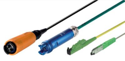
Figure 2: A fiber adapter cable with LCD SFP (Lucent Connector Duplex Small Form-factor Pluggable) connectors on one side and an MTP QSFP multi-fiber connector on the other side. Source: Sylex.
Characteristics of Optical Fiber Connectors
The following characteristics can be relevant for the selection of fiber connectors:
- A connector should provide a reliable low-loss contact in the plugged-in state. One specifies a typical coupling loss in decibels. It is called the attenuation or insertion loss. Its measurement is defined by IEC standard 61753-1. Typical values of the insertion loss are of the order of 0.5 dB. When the same connector is plugged in and out repeatedly, the insertion loss may exhibit significant variations (non-perfect repeatability).
- There are special high-quality ultra-low loss fiber connectors which even for single-mode fibers reliably achieve insertion losses <0.1 dB; their fabrication employs special active alignment techniques for very accurate positioning of the ferrule bore. They are applied in particularly loss-sensitive applications such as quantum communications.
- Note that the insertion loss achieved also depends on qualities of the fiber itself, such as eccentricity and effective mode area.
- For some applications, the reflection loss (= return loss), i.e., the attenuation for light being reflected at the interface, can also be very relevant; it should be as high as possible. Values above 20 dB (i.e., less than 1 % reflectivity) are easily achieved — with some connector versions (HRL = high return loss) even more than 50 dB.
- Note that the insertion losses are usually substantially higher than what one would expect from the return loss alone — particularly for fiber connectors using angled fiber endfaces, where reflected light does not get back into the fiber.
- Note also that increased reflections can occur as a result of a tiny air gap between the connectorized fibers (e.g. due to an incorrect angle of the fiber tip): the Fresnel reflections at both interfaces can cancel each other only if the gap width is much smaller than one wavelength.
- In principle, one could also suppress reflections with anti-reflection coatings on the fiber endfaces, but this technique is not very common due to various practical issues, such as the fragility of coatings and the substantial effort to produce them.
- Many fiber connectors are rarely disconnected or reconnected in normal use, but for some application a higher number of reconnections (mating cycles) must be possible during the connector's lifetime. Thousands of mating cycles are not easily achieved, as the contact between the fiber ends needs to be very precise and clean.
- It may also matter how easily and reliably fibers can be connectorized, particularly if that needs to be done in the field. The sensitivity to environmental factors such as cleanliness and vibrations also varies, and the required equipment depends on the connector type.
- In some cases, the power handling capability is relevant.
- There are multi-fiber connectors, which can connect multiple fibers.
- The dimensions of connectors are relevant particularly if many connections need to be done to devices of moderate size.
Types of Optical Fiber Connectors
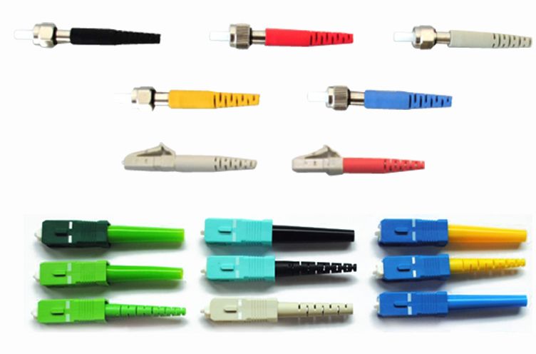
The most common fiber connectors are those of ST, FC, SC and LC type, and there are various versions of those. A short overview is given in the following:
Single-fiber Connectors
ST Connectors
ST (Straight Tip) connectors are most popular for fiber-optic networks based on multimode fibers, as are usually used within buildings. The fiber is placed in a relatively long cylindrical keyed ferrule (often made of ceramic), providing a tight contact (physical contact) of the fiber ends. ST connectors contain a spring-loaded bayonet mount.
FC Connectors
FC connectors (“ferrule connector”) are a popular type for single-mode fibers. They contain a floating ferrule with 2.5 mm diameter, into which the fiber is inserted (with the risk of scratching the fiber end). They provide a good mechanical isolation of the contact, allowing the use in high-vibration environments, but need to be handled quite carefully, with alignment of the ferrule's key when plugging it in. That key prevents rotation of the fiber when the plug is screwed into the receptacle. This is important for angled fiber ends (see below) and for polarization-maintaining fibers. Unfortunately, there are two mutually incompatible versions with key widths of 2 mm (reduced version, “type R”) and 2.14 mm (“type N”), respectively.
The standard version FC/PC involves a standard “physical contact” with a slightly rounded fiber surface; the fiber tip is polished after insertion into the ferrule. The ferrule is spring-loaded, providing a well-defined contact force when the connector is plugged in. Higher-quality fiber tip polishing is used in FC/SPC and FC/UPC connectors (with “super” or “ultra” polish). This provides higher return loss and lower insertion loss.
FC/APC connectors use angled fiber endfaces to obtain a high return loss (even in the disconnected state), but normally at the cost of increased insertion loss. Of course, fiber ends with a carefully controlled tilt angle are more difficult to make, and the two angled fibers need to be inserted properly such the surfaces fit together.
FC connectors are often used for single-mode fibers including polarization-maintaining fibers, but are increasingly replaced with SC and LC connectors.
SC Connectors
SC connectors (“subscriber connectors” or “standard connectors”) are general-purpose push/pull snap-in connectors for single-mode fibers. The fiber lies in a ceramic ferrule, and its orientation is controlled with a key. The rectangular shape of the connector leads to a defined orientation concerning rotations (in contrast e.g. to FC connectors). The snap-in mechanism makes the handling less critical than with FC connectors.
SC connectors are increasingly used in network applications, particularly with single-mode fibers. They are also available in duplex versions, i.e., with connections for two fibers.
LC Connectors
LC connectors (“Lucent connectors”) are particularly small, belonging to the “small form factor” connectors (SFF connectors). It contains a ferrule with only 1.25 mm diameter. It is often used for single-mode fibers. Duplex versions (LCD) are also available.
SMA Connectors
SMA connectors (SubMiniature version A) were originally adapted from the electrical SMA coaxial connector design. They are threaded, providing a secure and robust connection, and were among the earliest fiber connectors used. They typically have a stainless steel ferrule (unlike modern ceramic ferrules), making them less precise for single-mode applications; they are mostly used for multimode fibers, e.g. for test equipment, and harsh environments where mechanical strength matters more than very low loss. Because of their insertion loss (not as low as modern connectors like SC or LC), they have been largely replaced in telecom but still appear in specialized or legacy systems.
Multi-fiber Connectors
While all the previously discussed connector types work with a single fiber only, or at most with two fibers for duplex versions, there are also multi-fiber connectors of various types, which can support substantially more, for example 12, 16 or 24 or even 72. A single fiber cable, containing multiple fibers, runs between the two connectors. This is often a flat fiber ribbon, i.e., a one-dimensional fiber array.
MPO Connectors
MPO (Multi-fiber Push-On) connectors are a common type of multi-fiber connectors. MTP (Multi-fiber Termination Push-on) is a high-performance version of MPO with enhanced features. It typically supports 12, 16, or 24 fibers, but can go up to 72 fibers. They are widely used in high-density cabling environments such as data centers, supporting 40G, 100G, and 400G network systems. They feature high density, fast installation, and the ability to change polarity and gender in the field.
On every MPO connector, there is a small rectangular plastic ridge called the key. It ensures the connector can only plug in one way and establishes fiber orientation.
MMC Connectors
MMC (Multi-fiber Miniature Connector) is a very small form factor multi-fiber connector (about 1/3 the size of traditional MPO/MTP connectors). There are 12, 16, and 24-fiber variants. They are used in modern data centers and high-bandwidth applications requiring a high fiber density. Both single-mode and multimode fibers can be used.
MT-RJ Connectors
MT-RJ (Mechanical Transfer Registered Jack) connectors are duplex connectors that integrate two fibers in a single polymer ferrule. They are used in local area networks (LANs) and other networking applications.
Q-RMC Connectors
Q-RMC (Rosenberger Multifiber Connector) is a robust industrial connector using the MT ferrule from MPO/MTP connectors and accommodating between 4 and 24 fibers. They are designed for use in harsh environments such as industrial, mining, and mobile communication applications. They have a push-pull closing mechanism and offer IP67 protection (waterproof, dustproof, corrosion-resistant).
MFS Connectors
MFS (Multiple Fiber System) connectors combine advanced polishing technology with the flexibility of the MT ferrule. They are available in 4, 8, and 12-fiber versions. They are used in both backplane and front panel applications, supporting high-density and high-reliability requirements. Both multi-mode and single-mode applications are possible.
General Remarks on Multi-Fiber Connectors
Most multi-fiber connectors are suitable for both single-mode and multimode fibers, although that can depend on the particular model.
Correctly combining the fiber inputs/outputs is vital. In optical fiber communications, for example, transmit (Tx) signals must reach corresponding receive (Rx) channels. Multi-fiber connectors can have different “polarities”:
- Polarity A uses a straight-through connection where position 1 at one end aligns with position 1 at the other end and so on. This often involves one end of the assembly having the connector in a “key up” position and the other in a “key down” position. (The “key” is a small protrusion on the connector body, and there is often a white dot indicating fiber position 1.)
- Polarity B uses a key up/key up configuration where the fiber positions are reversed at each end (for example, 1 to 12 and 12 to 1).
- Polarity C involves flipping fiber pairs within the cable (e.g., position 1 to position 2, position 2 to position 1, etc.). This method is less common.
For duplex connectors (with just two fibers on each end), polarity B is also called “crossed”.
Note that different fibers may carry data signals traveling in different directions. Such bidirectional transmission can be done with different arrangements of transmit (Tx) and receive (Rx) fibers, for example:
- paired arrangements with odd fibers for Tx, even fibers for Rx
- split arrangements, e.g. with fibers 1-6 for Tx, 7-12 for Rx
- bidirectional on single fiber: use each fiber for both directions, typically at different wavelengths
Connecting Dissimilar Fibers
Usually, fiber connectors are used for connecting fibers of the same kind, i.e., with identical parameters like core diameter, numerical aperture, etc. If the fibers are dissimilar, substantially increased coupling losses can result.
For single-mode fibers, the essential factor is the spatial overlap of mode fields. This overlap is usually quite strong if the effective mode area of both fibers is similar — although different shapes of the mode fields also matter.
Fiber-Optic Connector Adapters
Connector adapters are often integrated into fiber patch panels, allowing connectors to be plugged in. They are available as single adapters and as adapter arrays (plates), e.g. with one adapter plate containing 12 LC duplex adapters.
Other types of connector adapters are used to join two fiber patch cables together. They have female connectors at both ends, allowing two male connectors to be plugged in. Such adapters are used for extending the length of fiber-optic cables.
Connector adapters are available for various types of connectors, including some for multiple fibers. They should be optimized for low coupling loss, which requires precise alignment of the fiber cores. There are also adapters for different types of connectors on the two sides.
See the article on fiber-optic adapters for more details.
Fiber-Optic Connector Couplers
Fiber-optic connector couplers are a connectorized kind of fiber couplers or splitters. They are used in complex network configurations where signal distribution or combination is required.
The core functions of fiber-optic connector couplers are:
- Splitting optical signals: Distribute an incoming optical signal into multiple output fibers (e.g., 1×2, 1×4 couplers).
- Combining signals: Combine multiple optical signals from different fibers into a single output fiber (e.g., 2×1, 4×1 couplers).
See the article on fiber couplers for details.
Unfortunately, the term fiber coupler is sometimes used for simple adapters, not involving splitting or combining.
Applications of Fiber Connectors
As fiber optics are intensively used for optical fiber communications, many fiber connectors are also used in that context — for example, in central offices of telephone companies, at Internet backbones or in fiber to the home installations. In applications with high fiber count, one usually uses multi-fiber connectors.
Laboratories also often use fiber cables with connectors, e.g. for transporting light to diagnostic instruments such as fiber-optic power meters and spectrometers. For complex setups such as mode-locked fiber lasers, for example, it is less common to use fiber connectors, partly because of the detrimental effects even of very small return losses. Mechanical splicing or fusion splicing is then often a better option.
Multimode fiber connectors are often installed in the field. Single-mode connectors, having tighter tolerances, are usually combined with their fibers in factories. In the field, one may fusion-splice such pig-tailed single-mode connectors to cables. (Single-mode connectors installed in the field tend to have higher losses.)
Tutorials
See our fiber optics tutorial on Passive Fiber Optics, part 6.
Frequently Asked Questions
What is an optical fiber connector?
A fiber connector is a device used to terminate an optical fiber cable, enabling a non-permanent, removable connection to another fiber or device. It functions similarly to an electrical connector.
What are insertion loss and return loss in fiber connectors?
Insertion loss, or attenuation, is the amount of optical power lost across the connection, which should be as low as possible. Return loss measures how much light is reflected back from the connector interface; a high return loss is desirable.
What are the most common types of single-fiber connectors?
The most common single-fiber connectors are ST, FC, SC, and LC. ST connectors are popular for multimode networks, while FC, SC, and LC are widely used for single-mode fibers, with LC being a small form factor type.
What is the difference between PC, UPC, and APC connectors?
These terms describe the fiber endface polish. PC (Physical Contact) is a standard polish with a slightly curved surface. UPC (Ultra Physical Contact) is a higher-quality polish for lower loss. APC (Angled Physical Contact) features an 8° angled endface to significantly reduce reflections, providing a very high return loss.
What is a multi-fiber connector?
A multi-fiber connector, such as an MPO connector, is designed to connect many fibers (e.g., 12, 24, or more) at once in a single housing. They are widely used in high-density environments like data centers.
What is connector polarity?
In multi-fiber connectors, polarity refers to the specific arrangement of fibers from one end of a cable to the other. Correct polarity ensures that transmit signals are properly routed to the corresponding receive channels.
When is splicing a better option than using a connector?
For sensitive applications like mode-locked fiber lasers, where even minimal back-reflections can be detrimental, permanent methods like fusion splicing are often preferred over connectors.
Suppliers
Sponsored content: The RP Photonics Buyer's Guide contains 79 suppliers for fiber connectors. Among them:

⚙ hardware
AMS Technologies carries a broad range of optical fiber connector kits for single mode (SM), multi mode (MM) and polarization maintaining (PM) optical fibers:
- Kits with the most popular optical connector types FC/PC, FC/APC and SMA905 come with a wide variety of bore sizes for different claddings.
- We also stock various kits for connector types like LC/PC, LC/APC, SC/PC, SC/APC, or ST/PC. Our fiber connector kits are available from stock with a crimp and boot set for Ø3.0 mm tubing. Alternative crimps and boots suitable for Ø2.0 mm or Ø0.9 mm tubing are also available. If you should not identify a fiber connector kit available from stock that meets your requirements, please contact AMS Technologies to discuss your custom optical fiber connector kit and receive a quote.

⚙ hardware
Diamond's fiber optic patch cords and assemblies accommodate a variety of cable types and constructions, making them ideal for a wide range of applications. Our expertise lies in the design, manufacture and assembly of high-precision fiber optic components. Our strengths at a glance:
- Low loss and high reliability: Our components are designed for minimal loss and maximum reliability.
- Repeatable excellence: We offer consistent quality with repeatable precision in every product.
- High power compliance: Our PS products can handle up to 16 watts of optical power in single mode (SM) fiber.
- Polarization ,aintaining: Our PM components provide precise control and manipulation of light polarization and are fully compatible with our high power interface.
- Operating extremes: We offer interconnects that operate over a wide range of very high and low temperatures.
- Wavelength versatility: Our fiber optic connectors are adaptable to short wavelengths.
Discover the unparalleled performance and versatility that Diamond brings to fiber optic connectivity. Raise your expectations and experience excellence in every connection.
Questions and Comments from Users
Here you can submit questions and comments. As far as they get accepted by the author, they will appear above this paragraph together with the author’s answer. The author will decide on acceptance based on certain criteria. Essentially, the issue must be of sufficiently broad interest.
Please do not enter personal data here. (See also our privacy declaration.) If you wish to receive personal feedback or consultancy from the author, please contact him, e.g. via e-mail.
By submitting the information, you give your consent to the potential publication of your inputs on our website according to our rules. (If you later retract your consent, we will delete those inputs.) As your inputs are first reviewed by the author, they may be published with some delay.