fiber endface inspection (original) (raw)
Definition: inspection of the quality of fiber endfaces, e.g. before splicing
Alternative term: fiber inspection probes
Category:  fiber optics and waveguides
- optics
- fiber optics
* fibers
* fiber connectors
* fiber-optic adapters
* fiber couplers
* fiber-optic pump combiners
* fiber bundles
* fiber endface inspection
* fiber microscopes
* fiber videoscopes
* fiber interferometers
* fiber connector inspectors
* cleaving of fibers
* fiber cleavers
* fiber joints
* fiber splices
* fiber Bragg gratings
* fiber cables
* fiber coatings
* fiber strippers
* fiber recoaters
* fiber coils
* fiber collimators
* fiber launch systems
* fiber lenses
* fiber loop mirrors
* fiber patch panels
* fiber shuffles
* fiber-optic attenuators
* fiber-optic plates
* fiber-optic tapers
* (more topics)
- fiber optics
Related: fiberscleaning of fiber endsfiber opticsfiber connectorsfiber-optic adapterscleaving of fibersfusion splicing of fibers
DOI: 10.61835/7w3 Cite the article: BibTex BibLaTex plain textHTML Link to this page! LinkedIn
Content quality and neutrality are maintained according to our editorial policy.
📦 For purchasing fiber endface inspection, use the RP Photonics Buyer's Guide — an expert-curated directory for finding all relevant suppliers, which also offers advanced purchasing assistance.
Contents
Introduction
Fiber optics is generally quite sensitive; tiny defects and even low levels of contamination on fiber endfaces can substantially degrade device and system performance. In fiber connectors, for example, particles or defects at the contact point can raise insertion loss, increase reflectance (reduce return loss), and permanently scratch the opposing fiber in a connector. Fusion splicing suffers when cleave angles are excessive. Therefore, effective inspection tools and practices are vital in this technology.
It is common to use various types of fiber endface inspection instruments which are specifically developed to analyze cleaved or polished endfaces of optical fibers or fiber connectors. One can verify that a fiber endface is clean, undamaged and overall within quality limits, e.g. before splicing fibers or mating connectors. While recognized contamination can usually be removed by cleaning, other defects often require new cleaving, i.e., preparing a new fiber end.
Some of these devices are made only for inspecting fiber connectors of certain types, others only for bare fiber ends, and some are suitable in both cases. V-grooves with clamps are common holders for bare fibers, while connectors need other fixing tools. Some probes can scan multi-fiber arrays.
All-purpose benchtop microscopes can in principle also be used, but specialized fiber inspection devices can be more convenient in various respects — beginning with mounting and also with specific inspection types, particularly for advanced instruments. They also yield more consistent (repeatable) results across different operators.
Advanced inspection instruments not only allow viewing, but perform automatic assessment with pass/fail tests and export detailed logs with serial numbers and job IDs.
Aspects of Inspection
Clean, undamaged fiber endfaces are often essential for optical performance. In detail, different aspects can be relevant, depending on the context.
Connectorized Fibers
Depending on the application, different details can be relevant. Some standards have been developed for connectorized fibers in order to produce more objective results:
- Visual cleanliness and defect criteria. IEC 61300-3-35 defines microscope requirements, inspection procedures, and quantitative acceptance criteria for debris, scratches, and defects in concentric zones around the core. The 2022 edition emphasizes inspecting the entire contact area (not just the core), including for rectangular MT ferrules. Many field fiber probes implement automated grading to this document.
- Interferometric geometry measurement. IEC 61300-3-47 specifies how interferometers must measure geometry parameters (e.g., measurement uncertainty, field of view) so results are comparable across instruments.
- Multi-fiber (MPO/MTP) geometry. IEC 61755-3-31 defines MT ferrule optical interface parameters (e.g., fiber height, planarity/coplanarity) that matter for low loss and good contact across all fibers.
Note that the cleanliness thresholds in IEC 61300-3-35 depend on connector type (PC vs. APC) and selected criteria set (e.g., single-mode vs multimode).
Bare Fiber Ends
For bare fiber ends, various aspects can be investigated:
- The endface should appear smooth and mirror-like with a crisp circular edge and no debris. How sensitive defects are depends very much on further steps — for example, fusion splicing has more critical demands than a fiber end emitting light into free space.
- Incorrect cleaver tension can cause hackle — a rough, flaky texture that scatters light and weakens splices. Micro-cracks and edge chips (small missing chunks around the rim) may also be observed. A ledge (lip, step) at the edge of the fiber can misalign the splice and trap debris.
- The cleave angle should often be close to perpendicular for standard splicing; single-mode fibers typically require cleave angles below 1°. In other cases, the intended angle can e.g. be 8° for applications that need low back-reflection.
- There should be no cracks spreading inward from the edge, and the glass edge should be intact (no chipping or steps).
- Contamination, e.g. residues from buffer coating or alcohol, are easy to spot with oblique lighting. Dust particles may also be seen.
There is no IEC bare-fiber visual inspection standard equivalent to IEC 61300-3-35 for connectors. Instead, non-standardized bare fiber inspection criteria are usually built into devices like fusion splicers (cleave angle tolerances, chip/mist detection). Industry guidelines (from ITU, Telcordia, training manuals) describe typical limits such as ≤1° cleave angle for single-mode, but these are recommendations, not global IEC requirements.
Applications of Fiber Inspection Devices
Fiber endface inspection devices are used both in manufacturing and in the field. Examples:
- In telecom and data centers, fiber connections need to be modified or repaired, e.g. at high-density fiber patch panels. Inspection may be done if a performance problem occurs, or better routinely after each change, as problems may be difficult to localize later.
- In manufacturing, some devices such as laser diodes or certain optical components require fiber pigtailing.
Some devices have integrated fiber inspection devices — for example, many fusion splicers.
Main Categories of Fiber Inspection Devices
Microscopes
Optical microscopes (eyepiece scopes) are compact, low-cost microscopes used for checking cleanliness and finding defects. Typically, they have a tube shape, allowing direct inspection of the endfaces, but often not of endfaces inside equipment or through bulkheads.
Fiber microscopes illuminate the properly fixed endface (often with an LED) and show a magnified image through an eyepiece. They are simple and can reveal very fine detail, but results are operator-dependent and not automatically aligned to pass/fail criteria.
Also note that viewing a fiber directly can be risky if it may carry substantial optical power — often in the infrared, so that it stays unnoticed. Therefore, many organizations prefer video scopes to avoid any risk of viewing live fibers directly.
Video Inspection Probes
These are usually handheld instruments used for the same purposes as fiber microscopes. Instead of an eyepiece, they have an image sensor and a display. That architecture has several implications:
- It allows splitting of probe and display: A small optical probe is connected to a handheld device with a display. The probe is suitable for examining ports in places which are hard to reach, while the display remains at a convenient location.
- As the user cannot be directly exposed to light emerging from the fiber, laser safety hazards are avoided.
- The electronics can provide useful additional functions. In the simplest case, instruments can offer autofocus and automatic image centering. Further, embedded software can analyze the view, providing automatic pass/fail analysis against the IEC visual-inspection standard, so that technicians can make quick, consistent decisions. Most systems store images and pass/fail results with timestamps and asset/job IDs for documentation; this may later help in troubleshooting. Automation features can be particularly helpful when inspecting many fibers. Even with automated inspection, substantial time (possibly a minute) may be needed for multiple-fiber connectors (MPO) with a high fiber count.
There are also benchtop instruments, possibly using an external monitor.
Common video probes have a field of view around 250 µm for single-fiber connectors, which comfortably covers the inspection zones. This in combination with the pixel count determines the limit of resolution, provided that the optics are of high quality. The absolute optical resolving power is often well below a good benchtop microscope, but handling, automation, and consistent grading typically make fiber video probes better for field work.
Different illumination types (coaxial or oblique) may be offered for focusing on different aspects of fiber endface quality.
Interferometric Endface Analyzers
These are particularly sensitive interferometric instruments for quality control during connector manufacturing and high-end termination work. They measure geometry very sensitively, but do not perform cleanliness grading.
The instrument reflects light from the polished surface and superimposes it with a reference beam to obtain interference fringes, which allow the generation of a 3D height map. From this map it computes key parameters such as the radius of curvature, apex offset (how far the highest point is from the fiber center), and fiber height (protrusion/undercut). These parameters strongly influence contact pressure, return loss, and long-term reliability.
For multi-fiber MT ferrules, specialized fixtures and algorithms evaluate fiber-to-fiber height differences and coplanarity across the array.
Integrated Analyzers
Some fiber end analyzers are integrated into other instruments. In particular, some modern splicers use their built-in microscopes to check the cleave quality just before splicing. They estimate cleave angle and flag chips, lip/step, or bad endface texture. It can save substantial time to discover such a problem before a splicing attempt which would fail or at least bring non-ideal results.
Inspection of Fiber Adapters
Fiber-optic adapters are pure mechanical parts, not containing fibers themselves. Nevertheless, their inspection can be vital, as contaminated or defective adapters can cause substantial problems:
- An adapter can be a source of recurring contamination of inserted connectors.
- Foreign objects in an adapter can damage every inserted fiber end.
- Sleeve wear or damage (cracks, chips or wear) may prevent ferrules from seating properly, leading to increased insertion loss or permanent scratches.
Many video inspection probes have bulkhead tips that insert into the adapter to look at the connector endface while it is in place. This also lets one notice if contamination seems to come back after cleaning connectors, pointing to a dirty adapter sleeve.
Technicians may shine a flashlight or use a loupe to check the sleeve bore for cracks, dirt, or shards.
Standard practice is to clean the adapter with a specially designed cleaning stick or swab, then re-inspect the connector endface after reinserting it. If the connector keeps failing cleanliness checks, the adapter may be at fault.
In data centers and telecom sites, a common rule is “inspect, clean, inspect” for both connectors and adapters. In case of doubt, an adapter is exchanged, as adapters are cheap compared to the cost of downtime.
Good Practices
Some generally advisable good practices in the context of fiber inspection:
- Before using a microscope with eyepiece, ensure that the fiber does not carry dangerous radiation (e.g. live telecom fibers).
- Before mating a connector, always inspect the endface for cleanliness — even if the fiber end is brand new.
- Always inspect a fiber endface again after cleaning or repairing. Cleaning attempts often fail (e.g. due to left-over contaminants, or attracting dust through static electricity), and this should be detected as soon as possible.
- Do not clean an endface which has passed an IEC test, as it is unlikely to get better, while it may well get worse.
- Avoid wet cleaning unless you can inspect immediately; residues can redeposit if dissolved material is not fully removed.
- Carefully study manuals of used instruments; they can contain valuable advice. Follow calibration intervals, especially for interferometers.
- Keep clean not only fiber connectors and adapters, but also the inspection equipment itself.
- Use dust covers where available, but do not trust that fibers must stay clean, as dust covers themselves can transmit contamination. Also, keep in mind that an endface which was plugged into a piece of equipment is not necessarily clean.
Frequently Asked Questions
What is fiber endface inspection?
It is the process of using specialized instruments, like microscopes or video probes, to analyze the endfaces of optical fibers for cleanliness, defects, and correct geometry to ensure optimal performance of connections.
Why is inspecting fiber endfaces so important?
It is crucial because even microscopic contamination or tiny defects on a fiber endface can substantially degrade performance by increasing insertion loss and reflectance, and can even cause permanent damage to mating connectors.
What are the main types of fiber inspection devices?
The main categories are optical microscopes for direct visual checks, video inspection probes which offer safer viewing and automated analysis, and interferometric analyzers for highly precise 3D geometry measurements.
What is the IEC 61300-3-35 standard for?
It is an international standard that defines microscope requirements, inspection procedures, and quantitative pass/fail criteria for debris, scratches, and defects on the endfaces of fiber optic connectors.
What are common defects on a cleaved bare fiber end?
Common defects include an incorrect cleave angle, hackle (a rough texture), micro-cracks, edge chips, a ledge at the fiber edge, and contamination from residues or dust particles.
What is the difference between a fiber microscope and a video inspection probe?
A fiber microscope has an eyepiece for direct viewing, posing a potential laser safety risk. A video probe uses an image sensor and a display, which is safer and often includes software for automated pass/fail analysis based on industry standards.
Why is it necessary to inspect fiber optic adapters?
Adapters must be inspected because they can be a source of contamination that is repeatedly transferred to clean connectors. A damaged or worn adapter sleeve can also cause poor ferrule alignment, leading to high loss and scratches.
Suppliers
Sponsored content: The RP Photonics Buyer's Guide contains 14 suppliers for fiber endface inspection. Among them:

⚙ hardware
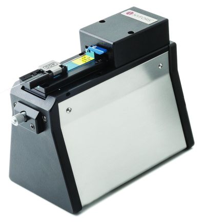
Nyfors offers high precision interferometers for checking the end face quality of cleaved optical fibers and for cleave process optimization. They show crisp and clear fringe patterns and come with software for advanced measurement functionality. Ideal for use in production settings and when working with difficult to cleave fibers in laboratory environments.
Fiber holder adapters available for use with cleavers and splicers from the major splicer manufacturers. This facilitates easy transfer of the fiber from cleaver to interferometer and then onto the splicer with no need for reclamping.

⚙ hardware
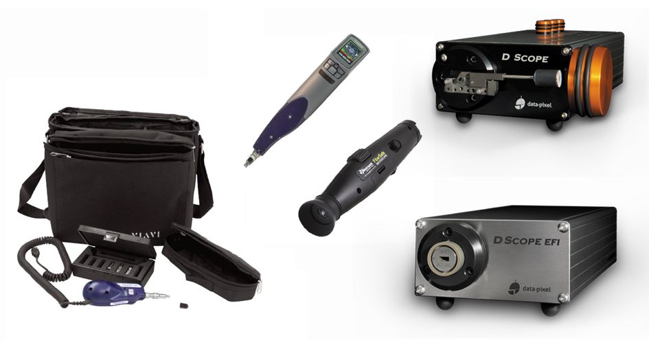
Particles contaminating the end face of optical fibers are typically only 2 to 20 µm in size, but substantially degrade the performance. Inspecting a fiber connection with a microscope that illuminates and magnifies the fiber tip is the only way to ensure that this connection is free of contamination and defects. Our extensive range of fiber optic microscopes for every application and budget provides intuitive and reliable inspection solutions for certification of new installations or troubleshooting of existing networks, avoiding subjective evaluations and estimates:
- hand-held analog or digital microscopes as companions for technicians in the field
- digital benchtop fiber inspection microscopes featuring automated fiber analysis software
- accessories for microscopes like various fiber inspection tips and adapters
Questions and Comments from Users
Here you can submit questions and comments. As far as they get accepted by the author, they will appear above this paragraph together with the author’s answer. The author will decide on acceptance based on certain criteria. Essentially, the issue must be of sufficiently broad interest.
Please do not enter personal data here. (See also our privacy declaration.) If you wish to receive personal feedback or consultancy from the author, please contact him, e.g. via e-mail.
By submitting the information, you give your consent to the potential publication of your inputs on our website according to our rules. (If you later retract your consent, we will delete those inputs.) As your inputs are first reviewed by the author, they may be published with some delay.