timing electronics for photonics (original) (raw)
Definition: electronics used in photonics for timing and synchronization purposes
 photonic devices
- electronics for photonics
- electronics for photodetection
- timing electronics for photonics
- laser drivers
- modulator drivers
Related: electronics for photonics
DOI: 10.61835/7fw Cite the article: BibTex BibLaTex plain textHTML Link to this page! LinkedIn
Content quality and neutrality are maintained according to our editorial policy.
📦 For purchasing timing electronics for photonics, use the RP Photonics Buyer's Guide — an expert-curated directory for finding all relevant suppliers, which also offers advanced purchasing assistance.
Contents
Introduction
Precision timing is critical in various photonics applications such as ultrafast spectroscopy, LIDAR, time-correlated single-photon counting (TCSPC), optical communication, quantum optics, and laser control systems. Various kinds of timing electronics are used for coordinating, synchronizing, and measuring events involving light — often on nanosecond, picosecond or even sub-picosecond timescales. Essential functions are explained in the following sections.
Pulse Generation
Pulse generators with precise delay and width control are required for various purposes in photonics:
- In actively Q-switched lasers, the Q-switch (usually an acousto-optic or electro-optic modulator) needs to be deactivated during precisely controlled time intervals, either with an internal clock or reacting to external trigger signals. The deactivation time must be long enough to allow for pulse build-up, but short enough to prevent parasitic pulses; it is typically in the microsecond range.
- In actively mode-locked lasers, an RF signal for driving an intensity or phase modulator needs to be kept in exact synchronism with one or several ultrashort pulses circulating in the laser resonator. This is achieved by automatically adjusting either the RF frequency or the resonator length (with a piezo transducer).
- Pulse pickers are mostly used to reduce the pulse repetition rate of a regular train of ultrashort pulses — often before further amplification, so that higher pulse energies become possible. Typically, one utilizes a photodiode signal monitoring the laser pulses (at a multi-megahertz repetition rate), and the driver needs to pick every Nth pulse, e.g. via an electro-optic modulator.
- In a regenerative amplifier, an ultrashort pulse to be amplified needs to be injected and later (after a certain number of resonator round-trips) extracted by operating one or two modulators at precisely controlled times. The used electronic driver may utilize a photodiode signal monitoring the available input pulses, and possibly (as a not common option) a second one for the circulating pulse (using a not completely reflecting resonator mirror as a leakage port).
Time-resolved Photodetection
Time-resolved detection of light is used in various applications like spectroscopy and LIDAR; some examples:
- Fluorescence lifetime spectroscopy involves measuring the decay time of fluorescence to probe molecular environments.
- Transient absorption spectroscopy captures absorption changes on nanosecond to picosecond scales.
- In LIDAR, the time of flight of returning light is used to obtain distances.
A wide range of electronics (and optoelectronics) are used for such purposes. Some examples:
- Time-to-Digital Converters (TDC) and Constant Fraction Discriminators (CFD) are used to measure time intervals between excitation and photon arrival.
- Avalanche photodiodes can be used for single-photon detection (→ photon counting), and are then called SPADs = Single-Photon Avalanche Diodes. There are also SPAD arrays which are integrated with additional electronics for temporally and spatially resolved measurements (time-resolved imaging).
- On longer times scales, fast CMOS and CCD arrays can be used for time-resolved imaging.
- Electronic gating systems synchronize detectors with pulsed excitation sources. Fast electronic shutters can filter out prompt emission and record only the delayed luminescence, increasing signal specificity. More generally, signals at not expected times may be filtered out based on time gating.
- High-speed electronic sampling circuits can record and store digitized data over some time interval, sometimes with sub-nanosecond temporal resolution.
Note that in some cases, even the fastest electronics are too slow for a measurement purpose. For example, waveforms of terahertz radiation cannot be sampled with electronics, but only obtained through optical sampling techniques. Relatively simple electronics may then be employed for controlling optical delay lines. Similarly, optical autocorrelators are used for measuring ultrashort pulse durations, where photodetectors are far too slow.
Clock Distribution and Phase Alignment
Areas like high-speed data communications, precision metrology and next-generation computing require accurate clock distribution and phase alignment with ultralow timing jitter. While the essential functions are performed with photonic means, sophisticated electronics are often needed in addition.
Frequency Metrology
Modern frequency metrology relies on optical clocks which can achieve extremely high timing precision. In order to make their timing information available not only locally, but also at remote places (including facilities with other precise clocks for timing comparisons), one requires clock distribution signals. Typically, the central part of an ultraprecise optical clock is a highly stabilized mode-locked laser generating a frequency comb with many spectral lines having extremely well-defined optical frequencies. The emitted light can be sent through optical fibers, which however introduce (especially over longer distances) some amount of phase noise through thermal effects and vibrations. Active noise cancellation techniques are therefore vital to achieve high timing precision. Essentially, one uses two-way transmission protocols, where signals transmitted in both directions are used to monitor and compensate the introduced phase noise.
Sophisticated electronics are involved in implementing such techniques. For example, there are advanced CMOS devices acting as driver-less metal-mesh clock trees and FPGA and SoC timing controllers for endpoints of distributed optical clocks. Time-to-digital converters (TDCs) can achieve sub-picosecond resolution, and FPGA- or microcontroller-based digital servos are used to stabilize frequency combs by controlling actuators like piezoelectric transducers (PZTs) and electro-optic modulators.
Optical Communications
Similar techniques can also be used for optical communications, both through optical fibers (the now dominating technique for terrestrial applications) and free space (e.g. satellite communication).
Synchronization in Large-scale Systems
In large facilities containing synchrotrons or free-electron lasers, for example, there are various complex synchronization tasks involving parts of a source (for example, electron pulses, laser pulses and RF signals), detectors and data acquisition systems. Timing precision down to the few-femtosecond scale may be required.
Such synchronization typically involves both state-of-the-art photonic and electronic devices, e.g. actively stabilized optical fiber links as explained above and various other kinds of automatic feedback loops for locking various kinds of oscillators.
Camera Synchronization
Camera synchronization ensures that two or more cameras (or a camera and another device, like a flash or monitor) operate in time alignment, so that frames and exposures line up correctly. This is relevant in various areas:
- multi-camera filming (live TV, 3D rigs, VR, scientific imaging)
- camera-to-light synchronization (flashes, strobes)
- camera-to-sensor synchronization (e.g., LiDAR, radar)
A trigger pulse (usually TTL logic, 3.3V or 5V square wave, rising or falling edge) can tell a camera when to start an exposure. Some cameras accept an external reference clock (e.g. with 10 MHz).
Professional broadcast/video cameras use generator locking (genlock) to keep their scanning/frame generation aligned. A black burst (PAL/NTSC) or tri-level sync (HD/4K) signal is fed to all cameras.
A camera may also output a strobe signal (a short TTL pulse when exposure begins). This is used to fire a flash or external light exactly when the shutter is open.
Suppliers
Sponsored content: The RP Photonics Buyer's Guide contains 13 suppliers for timing electronics for photonics. Among them:

⚙ hardware
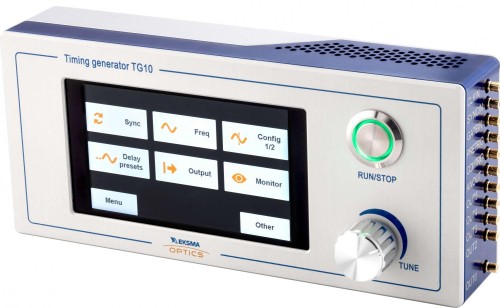
The TG10 is a timing generator dedicated to the synchronization of laser systems and laser components: Pockels cell drivers, acousto-optical modulator drivers, laser diode and flash lamp drivers, detectors, data acquisition systems, laser pulse pickers, etc. The TG10 is designed to create up to 8 delayed output sequences precisely synchronized to the internal or external clock. A photodetector or electrical signal can be used as the input source to be synchronized with.

⚙ hardware
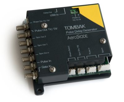
SHIPS TODAY: the AeroDIODE TOMBAK pulse delay generator provides high frequency pulses, delays, and bursts. It is an ideal testing and timing control instrument for electronics, lasers, or camera setup. The adjustable detection threshold is as low as a few mV. This makes it an ideal tool for detecting ultra-short pulses through a photodiode. The pulse delay generator offers several operating modes including stand-alone generator, digital delay generator, frequency divider, burst generator, pulse picker, voltage level converter and arbitrary waveform generator (AWG). It is often used in a fiber modulation setup with EOMs, AOMs or SOAs. Applications include component testing, laser timing control, laser pulse picking, camera synchronization etc.

⚙ hardware

The ICMSG-100-5 digital pulse/delay generator is a four-channel device for synchronizing various types of equipment. It is primarily used in scientific and technological industries, such as laser photonics. It provides precise control over the timing of electronic signals, allowing for accurate synchronization of components in complex systems, such as pulsed laser systems, optics experiments, and other advanced technologies. The device is available in versions for laboratory use and for OEM use.

⚙ hardware
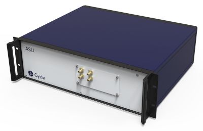
Cycle’s fully automated E-SYNC is a versatile device which can measure the timing jitter or phase noise between any optical or microwave signal.
It generates a baseband signal that is proportional to the timing error between the two inputs, which in turn can be used in a phase-locked loop configuration to synchronize a laser to a microwave source or vice versa or two microwave sources.
Questions and Comments from Users
Here you can submit questions and comments. As far as they get accepted by the author, they will appear above this paragraph together with the author’s answer. The author will decide on acceptance based on certain criteria. Essentially, the issue must be of sufficiently broad interest.
Please do not enter personal data here. (See also our privacy declaration.) If you wish to receive personal feedback or consultancy from the author, please contact him, e.g. via e-mail.
By submitting the information, you give your consent to the potential publication of your inputs on our website according to our rules. (If you later retract your consent, we will delete those inputs.) As your inputs are first reviewed by the author, they may be published with some delay.