Apply projection and camera views (original) (raw)
In the OpenGL ES environment, projection and camera views allow you to display drawn objects in a way that more closely resembles how you see physical objects with your eyes. This simulation of physical viewing is done with mathematical transformations of drawn object coordinates:
- Projection - This transformation adjusts the coordinates of drawn objects based on the width and height of the
[GLSurfaceView](/reference/android/opengl/GLSurfaceView)where they are displayed. Without this calculation, objects drawn by OpenGL ES are skewed by the unequal proportions of the view window. A projection transformation typically only has to be calculated when the proportions of the OpenGL view are established or changed in the[onSurfaceChanged()](/reference/android/opengl/GLSurfaceView.Renderer#onSurfaceChanged%28javax.microedition.khronos.opengles.GL10, int, int%29)method of your renderer. For more information about OpenGL ES projections and coordinate mapping, seeMapping coordinates for drawn objects. - Camera View - This transformation adjusts the coordinates of drawn objects based on a virtual camera position. It’s important to note that OpenGL ES does not define an actual camera object, but instead provides utility methods that simulate a camera by transforming the display of drawn objects. A camera view transformation might be calculated only once when you establish your
[GLSurfaceView](/reference/android/opengl/GLSurfaceView), or might change dynamically based on user actions or your application’s function.
This lesson describes how to create a projection and camera view and apply it to shapes drawn in your [GLSurfaceView](/reference/android/opengl/GLSurfaceView).
Define a projection
The data for a projection transformation is calculated in the [onSurfaceChanged()](/reference/android/opengl/GLSurfaceView.Renderer#onSurfaceChanged%28javax.microedition.khronos.opengles.GL10, int, int%29)method of your [GLSurfaceView.Renderer](/reference/android/opengl/GLSurfaceView.Renderer) class. The following example code takes the height and width of the [GLSurfaceView](/reference/android/opengl/GLSurfaceView) and uses it to populate a projection transformation [Matrix](/reference/android/opengl/Matrix) using the [Matrix.frustumM()](/reference/android/opengl/Matrix#frustumM%28float[], int, float, float, float, float, float, float%29) method:
Kotlin
// vPMatrix is an abbreviation for "Model View Projection Matrix" private val vPMatrix = FloatArray(16) private val projectionMatrix = FloatArray(16) private val viewMatrix = FloatArray(16)
override fun onSurfaceChanged(unused: GL10, width: Int, height: Int) { GLES20.glViewport(0, 0, width, height)
val ratio: Float = width.toFloat() / height.toFloat()

// this projection matrix is applied to object coordinates
// in the onDrawFrame() method
Matrix.frustumM(projectionMatrix, 0, -ratio, ratio, -1f, 1f, 3f, 7f)
}
Java
// vPMatrix is an abbreviation for "Model View Projection Matrix" private final float[] vPMatrix = new float[16]; private final float[] projectionMatrix = new float[16]; private final float[] viewMatrix = new float[16];
@Override public void onSurfaceChanged(GL10 unused, int width, int height) { GLES20.glViewport(0, 0, width, height);
float ratio = (float) width / height;

// this projection matrix is applied to object coordinates
// in the onDrawFrame() method
Matrix.frustumM(projectionMatrix, 0, -ratio, ratio, -1, 1, 3, 7);
}
This code populates a projection matrix, mProjectionMatrix which you can then combine with a camera view transformation in the [onDrawFrame()](/reference/android/opengl/GLSurfaceView.Renderer#onDrawFrame%28javax.microedition.khronos.opengles.GL10%29) method, which is shown in the next section.
Note: Just applying a projection transformation to your drawing objects typically results in a very empty display. In general, you must also apply a camera view transformation in order for anything to show up on screen.
Define a camera view
Complete the process of transforming your drawn objects by adding a camera view transformation as part of the drawing process in your renderer. In the following example code, the camera view transformation is calculated using the [Matrix.setLookAtM()](/reference/android/opengl/Matrix#setLookAtM%28float[], int, float, float, float, float, float, float, float, float, float%29)method and then combined with the previously calculated projection matrix. The combined transformation matrices are then passed to the drawn shape.
Kotlin
override fun onDrawFrame(unused: GL10) { ... // Set the camera position (View matrix) Matrix.setLookAtM(viewMatrix, 0, 0f, 0f, 3f, 0f, 0f, 0f, 0f, 1.0f, 0.0f)
// Calculate the projection and view transformation
Matrix.multiplyMM(vPMatrix, 0, projectionMatrix, 0, viewMatrix, 0)

// Draw shape
triangle.draw(vPMatrix)
Java
@Override public void onDrawFrame(GL10 unused) { ... // Set the camera position (View matrix) Matrix.setLookAtM(viewMatrix, 0, 0, 0, 3, 0f, 0f, 0f, 0f, 1.0f, 0.0f);
// Calculate the projection and view transformation
Matrix.multiplyMM(vPMatrix, 0, projectionMatrix, 0, viewMatrix, 0);

// Draw shape
triangle.draw(vPMatrix);
}
Apply projection and camera transformations
In order to use the combined projection and camera view transformation matrix shown in the previews sections, first add a matrix variable to the vertex shader previously defined in the Triangle class:
Kotlin
class Triangle {
private val vertexShaderCode =
        // This matrix member variable provides a hook to manipulate
        // the coordinates of the objects that use this vertex shader
        "uniform mat4 uMVPMatrix;" +
        "attribute vec4 vPosition;" +
        "void main() {" +
        // the matrix must be included as a modifier of gl_Position
        // Note that the uMVPMatrix factor *must be first* in order
        // for the matrix multiplication product to be correct.
        "  gl_Position = uMVPMatrix * vPosition;" +
        "}"

// Use to access and set the view transformation
private var vPMatrixHandle: Int = 0

...
}
Java
public class Triangle {
private final String vertexShaderCode =
    // This matrix member variable provides a hook to manipulate
    // the coordinates of the objects that use this vertex shader
    "uniform mat4 uMVPMatrix;" +
    "attribute vec4 vPosition;" +
    "void main() {" +
    // the matrix must be included as a modifier of gl_Position
    // Note that the uMVPMatrix factor *must be first* in order
    // for the matrix multiplication product to be correct.
    "  gl_Position = uMVPMatrix * vPosition;" +
    "}";

// Use to access and set the view transformation
private int vPMatrixHandle;

...
}
Next, modify the draw() method of your graphic objects to accept the combined transformation matrix and apply it to the shape:
Kotlin
fun draw(mvpMatrix: FloatArray) { // pass in the calculated transformation matrix ...
// get handle to shape's transformation matrix
vPMatrixHandle = GLES20.glGetUniformLocation(mProgram, "uMVPMatrix")

// Pass the projection and view transformation to the shader
GLES20.glUniformMatrix4fv(vPMatrixHandle, 1, false, mvpMatrix, 0)

// Draw the triangle
GLES20.glDrawArrays(GLES20.GL_TRIANGLES, 0, vertexCount)

// Disable vertex array
GLES20.glDisableVertexAttribArray(positionHandle)
}
Java
public void draw(float[] mvpMatrix) { // pass in the calculated transformation matrix ...
// get handle to shape's transformation matrix
vPMatrixHandle = GLES20.glGetUniformLocation(mProgram, "uMVPMatrix");

// Pass the projection and view transformation to the shader
GLES20.glUniformMatrix4fv(vPMatrixHandle, 1, false, mvpMatrix, 0);

// Draw the triangle
GLES20.glDrawArrays(GLES20.GL_TRIANGLES, 0, vertexCount);

// Disable vertex array
GLES20.glDisableVertexAttribArray(positionHandle);
}
Once you have correctly calculated and applied the projection and camera view transformations, your graphic objects are drawn in correct proportions and should look like this:
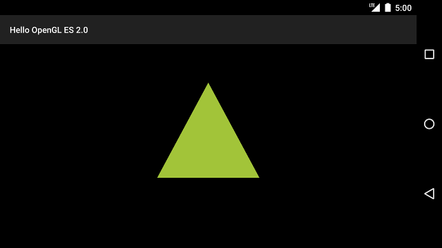
Figure 1. Triangle drawn with a projection and camera view applied.
Now that you have an application that displays your shapes in correct proportions, it's time to add motion to your shapes.