X.25 Networking Guide - FarSite Communications Ltd (original) (raw)
This guide explains X.25 Networking by comparing X.25 to networks with which the reader may be more familiar, namely TCP/IP Networks (such as the Internet) and the Public Switched Telephone Network (PSTN)
Network Interface Connector Standards - Defined and Explained
What is an X.25 Network?
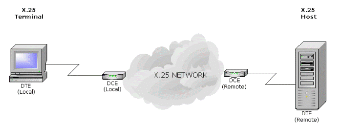
An X.25 network provides a means by which one X.25 DTE (a Terminal or Host of some kind) can exchange data with one or more other X.25 Host, on the other side of the network.

Data is carried within individual packets – X.25 is often referred to as a Packet Switching Protocol. This makes it similar to a TCP/IP network – the difference is that IP networks employ a Connectionless protocol: each packet is routed according to the information within that packet (typically by using the Destination Address).
By contrast, X.25 is a Connection-Oriented protocol: the routing information used by the network is carried only in the packets used to establish the connection; thereafter addressing information is not required. This does, however, mean that the X.25 network switching nodes need be aware of each connection, unlike IP routers.
X.25 Layers
The X.25 protocol is divided into 3 layers (or Levels); TCP/IP, on the other hand is divided into 4 layers.
| Layer | Description | X.25 | TCP/IP equivalence |
|---|---|---|---|
| 1 | Physical Layer | V.24, X.21, V.35, etc | Same as X.25, and others not normally used by X.25(too many to mention) |
| 2 | Data Link Layer | LAPB | Many, such as PPP, SLIP, Cisco HDLC, etc and even X.25 itself (see below)! |
| 3 | Network Layer | X.25 PLP | IP |
| 4 | Transport Layer | (none) | TCP or UDP |
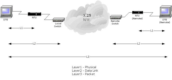
Each of these layers is independent. The Physical layer includes the mechanical and electrical aspect of communications – in other words, cabling. The X.25 Data Link Layer provides the reliable link between the DTE and the DCE (or Network), and the X.25 Packet Layer Protocol (PLP) provides the information necessary to make and maintain a connection across the network.

It’s probably most useful to think of Layer 1 as being the physical connection to the network NTU or modem, Layer 2 as being the Logical Link between the DTE and the local network switching node, and a Layer 3 Virtual Circuit as being the connection to the remote DTE.
The X.25 Guide was proudly written by FarSite Communications Ltd.