Digital DC Voltmeter using 7-Segment Display and Pic Microcontroller (original) (raw)
In this tutorial, we will design a digital voltmeter using a 7-segment display and pic microcontroller. Usually, we use LCDs to display sensor data. In the last tutorial, we designed a DC digital voltmeter with a 16×2 Liquid crystal display. But in this post, instead of using LCD, we will use a four-digit 7-segment display to print voltage value. We will use the ADC module of PIC16F877a microcontroller to measure DC voltage.
Components Required
- PIC16F877A Microcontroller
- 4-digital Seven Segment Display
- Resistors
- Crystal Oscillator
- Capacitors
- NPN transistors
Digital Voltmeter with 7-segment display circuit diagram
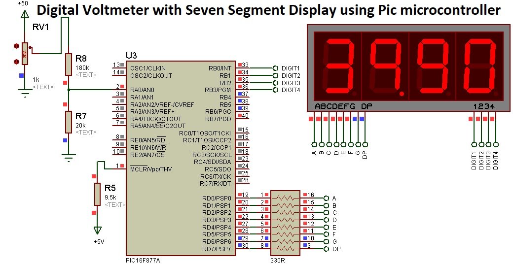
A picture below shows the circuit diagram of DC voltmeter with four digit seven-segment display and voltage divider circuits interfacing with PIC16F877A microcontroller. But you can use any other pic microcontroller also.
How to measure DC voltage?
Firstly, lets discuss do we need to use a voltage divider circuit. The simple and basic reason to use voltage divider circuit is that pic microcontroller operating voltage is between 0-5 volts. Hence, built-in ADC module of PIC16F877A microcontroller can read analog signal in the range 0 to 5 volts only. Therefore, in order to measure dc voltages higher than this level, we need come up with a solution to step down input voltage. This is the reason a voltage divider circuit is required in this project.

A voltage divider circuit as its name suggests divides the voltage between across two resistors. As you can see from the above circuit of dc voltmeter, we used two resistors
R9 = 180K
R7 =20k
The formula of voltage divider is very simple that is
VOUT = (R7/(R7+R9) x VIN)For example, if input voltage is 19 volts, the output voltage will be:
VOUT = (20k/(20k+180k) x 19) = 1.9 volts1.9 volts is less than 5 volts. Therefore, we can measure this voltage with ADC of PIC16F877A microcontroller. If you see from the voltage divider formula, the voltage step down or reduction factor is 20/200 = 1/10
Step down factor = 1/10We can use this reduction factor in our programming to get actual voltage by measuring only the output voltage of voltage divider. We will measure step -down voltage that is the output of voltage divider circuit. But, inside our program, we will multiply measured voltage value with the reduction factor to get actual value of input voltage.
We used analog channel AN0/RA0 of PIC16F877A microcontroller. We have already post a guide on how to use analog digital module of Pic Microcontroller, you can read this post:
Connection with 4-digital seven-segment device
As you know that there are two types of 7-segment displays: namely common anode and common cathode type. We will use a common cathode type 4-digit device to display measure voltage value.
Connect PORTD with A-g pins of 4-digital seven-segment display using 330ohm current limiting resistors. Also connect RB0-RB3 pins of PORTB with control pins 1-4 of display device. Same data lines are used to send binary pattern to each digit of display device, but control lines select that at which place (7-segment) we want to display a digit.
To explore further on 7-segment displays interfacing with pic microcontrollers, go through these in-depth guides:
- Seven-Segment displays interfacing with pic microcontroller
- How to print ADC value on 7-segment using pic microcontroller
Digital voltmeter with 7-segment display Simulation
This circuit is simulated with proteus. As you can see, we connect a 50 volts DC source with a voltage divider circuit through a variable resistor. We use this variable resistor to apply a variable voltage to the circuit.
We can observe the same voltage on a 4-digit seven-segment device according to the input voltage variation.
MikroC Code
This code is written using MikroC for Pic compiler. Create a new project with MikroC compiler by selecting PIC16F877A microcontroller and set frequency to 8MHz. If you don’t know how create new project in mikroC, we suggest you read this post:
After creating a new project with MikroC, set configuration bits to these values:
CONFIG : $2007 : 0x2F4AAfter that copy this code and compile it with MikroC for Pic compiler.
// define name to each control signal for 7-segment
sbit digit1 at PORTB.B0;
sbit digit2 at PORTB.B1;
sbit digit3 at PORTB.B2;
sbit digit4 at PORTB.B3;
// This array stores binary bit pattern that will be send to PORTD
unsigned char binary_pattern[]={0x3F,0x06,0x5B,0x4F,0x66,0x6D,0x7D,0x07,0x7F,0x6F}; // without Dp turn
unsigned char display1[10]= {0xBF,0x86,0xDB,0xCF,0xE6,0xED,0xFD,0x87,0xFF,0xE7};    // with dp turn on

// variables to store digits, digital value and output voltage
unsigned int a1,a2,a3,a4; // temporary variables to store data of adc
int adc_value; //store output value from Analog Read functoion
unsigned int number;
long tlong;
unsigned int voltage;

// this function retrive each digita that will displayed on device
void get_digits()
  {
           a1 =  voltage / 1000u;   // holds 1000's digit
           a2 = ((voltage/100u)%10u); // holds 100's digit
           a3 = ((voltage/10u)%10u);  // holds 10th digit
           a4 = (voltage%10u);  // holds unit digit value
   }

// this function displays measured voltage on seven-segments
void display_voltage()
 {
            PORTD = binary_pattern[a2]; // send 1000's place data to fourth digit
            digit1 = 0;   //  turn on forth display unit
            delay_ms(3);
            digit1 = 1;   //  turn off forth display unit
            PORTD = display1[a3];  // send 100's place data to 3rd digit
            digit2 = 0;    //  turn on 3rd display unit
            delay_ms(3);
            digit2 = 1;  //  turn off 3rd display unit
            PORTD = binary_pattern[a4];  // send 10th place data to 2nd digit
            digit3 = 0;  //  turn on 2nd display unit
            delay_ms(3);
            digit3 = 1;   //  turn off 2nd display unit
            PORTD=binary_pattern[a1];  // send unit place data to 1st digit
            digit4 = 0;  //  turn on 1st display unit
            delay_ms(3);
            digit4 = 1;  //  turn off 1st display unit
   }
void interrupt()
{

            get_digits();   // call function to split data
            display_voltage(); //call display_data() function to output value to seven segment

            T0IF_bit = 0;  // clear source of timer0 interrupt
}
void main(void)
{
    TMR0   = 0;         // timer0 reset bit
    OPTION_REG = 0x83;  // select prescalar value 1:16 for timer0
    INTCON = 0xA0;      // turn on global interrupt and timer0 overflow interrupt
    TRISD = 0x00; //define PORTD as a output pin
    PORTD=0x00;   // initialize PORTD pins to active low
    TRISB=0x00;// Set PORTB as a output port
  // set control pins pins initially active high
    digit1 = 1;
    digit2 = 1;
    digit3 = 1;
    digit4 = 1;

    while(1)
    {

           adc_value = ADC_Read(0);  // read data from channel 0
           tlong = (float)adc_value*0.488768555;
           voltage = tlong;
           //delay_ms(100);  // wait 100 milliseconds

    }

}
MPAB XC8 Code
This code is for MPLAB XC8 Compiler. If you don’t know how to use MPLAB and XC8 compiler, you can read this complete in-depth guide:
After creating a new project, set configuration bits by generating configuration bit file with MPLAB XC8. While generating this file, select the HS crystal option and leave the remaining setting as to default settings.
#include <xc.h>
#define _XTAL_FREQ 20000000 //define crystal frequency to 20MHz
#define digit1 PORTBbits.RB0
#define digit2 PORTBbits.RB1
#define digit3 PORTBbits.RB2
#define digit4 PORTBbits.RB3
// This array stores binary bit pattern that will be send to PORTD
unsigned char binary_pattern[]={0x3F,0x06,0x5B,0x4F,0x66,0x6D,0x7D,0x07,0x7F,0x6F};
unsigned char display1[10]= {0xBF,0x86,0xDB,0xCF,0xE6,0xED,0xFD,0x87,0xFF,0xE7};    // with dp turn on
unsigned int a1,a2,a3,a4;
unsigned int counter = 0;
int adc_value; //store output value from Analog Read functoion
unsigned int number;
long tlong;
unsigned int voltage;
void Analog_setting(){
    ADCON0 = 0x81;
    ADCON1 = 0x02;
}

unsigned int Analog_read(unsigned char channel){
    int aadc,bbdc, ccdc;
    if(channel>7)return 0;
    ADCON0 = ADCON0 & 0xC5;
    ADCON0 = ADCON0 | (channel << 3);
    __delay_ms(2);
    ADCON0bits.GO_DONE = 1;
    while(ADCON0bits.GO_DONE);
    aadc = ADRESH;
    aadc = aadc<<2;
    bbdc = ADRESL;
    bbdc = bbdc >>6;
    ccdc = aadc|bbdc;
    return ccdc;

}
void main(void)
{
    Analog_setting();
    TRISD = 0x00; //define PORTD as a output pin
    PORTD=0X00;   // initialize PORTD pins to active low
    TRISB=0X00;
    digit1 = 1;
    digit2 = 1;
    digit3 = 1;
    digit4 = 1;
    while(1)
    {
          adc_value = Analog_read(0);  // read data from channel 0
           tlong = (float)adc_value*0.488768555;
           voltage = tlong;

           a1 = voltage / 1000;   // holds 1000's digit
           a2 = ((voltage/100)%10); // holds 100's digit
           a3 = ((voltage/10)%10);  // holds 10th digit
           a4 = (voltage%10);  // holds unit digit value


PORTD=binary_pattern[a2]; // send 1000's place data to fourth digit
digit1=0;   //  turn on forth display unit
__delay_ms(3);
digit1=1;   //  turn off forth display unit
PORTD=display1[a3];  // send 100's place data to 3rd digit
digit2=0;    //  turn on 3rd display unit
__delay_ms(3);
digit2=1;  //  turn off 3rd display unit
PORTD=binary_pattern[a4];  // send 10th place data to 2nd digit
digit3 = 0;  //  turn on 2nd display unit
__delay_ms(3);
 digit3 = 1;   //  turn off 2nd display unit
PORTD=binary_pattern[a1];  // send unit place data to 1st digit
digit4 = 0;  //  turn on 1st display unit
__delay_ms(3);
digit4 = 1;  //  turn off 1st display unit


    }
    return ;
}