ESP32 Pinout Reference (original) (raw)
This tutorial focuses on the pinout of the ESP32 development board, specifically the ESP32 devkit that incorporates the ESP-WROOM-32 module. While various versions of the ESP32 chip exist in the market, the ESP32 devkit utilizes the ESP-WROOM-32 module. Fortunately, the functionality of all GPIO pins remains consistent across all ESP32 development boards.
Many people are asking questions about how to use its GPIO pins. Which GPIO pin can be used as a digital input-output pin? Which GPIO pin can be used as an analog pin? And which pin should not be used to use this board safely? You will get the answer to these questions in this article. So now let’s begin with the introduction of GPIO pins of the ESP32 development board.
you can check these articles on ESP32:

- Introduction to the ESP32 development board
- How to install ESP32 in Arduino IDE – step-by-step guide
you can check more information about this chip here.
ESP32 Main Features
The followings are the main features of ESP32 :
- It has onboard 18 Analog to digital converts ADCs. Each ADC is 12-bit SAR technology-based.
- 2 digital to analog converts DACs.
- It integrates 9 touch sensors.
- For communication, it has 2 UART communications channels, 2 I2C communications interfaces, two I2S channels, and one CAN communication interface.
- It has 16 pulse width modulation channels.
- It also has a cryptographic hardware acceleration module for various cryptographic algorithms like RSA, and AES.
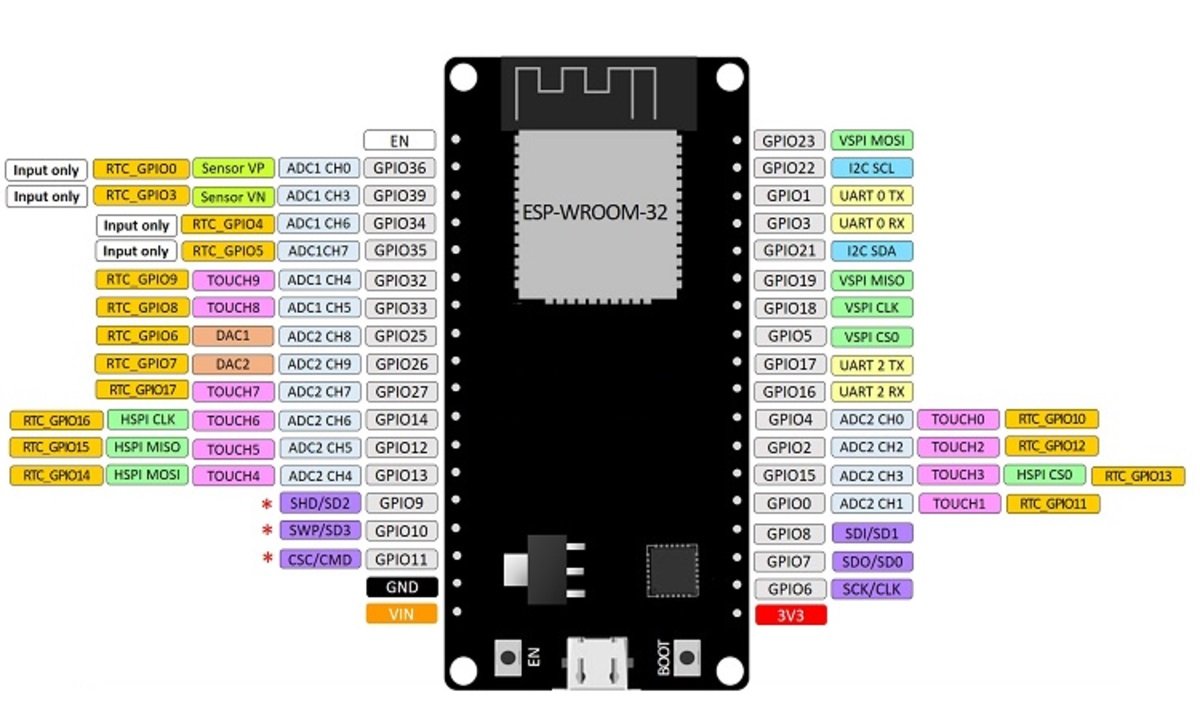
There are different types of ESP32 development kits available but the function of GPIO pins remains the same across all development boards. You can define the pins the same way in firmware also. The following picture shows the pinout diagram of the ESP32 DEVKIT V1 DOIT board. In your version of the ESP32 development kit, each GPIO pin may be exposed on a different pin number.
ESP32 Pin Configuration Details
As mentioned earlier, the chip used with this board has 48 GPIO pins, but all pins are not accessible through the pinout of development boards. This ESP32 devkit has 36 GPIO pins and 18 on each side of the board as shown in the picture above. It has 34 GPIO pins and each pin has multiple functionalities which can be configured using specific registers. There are many types of GPIOs available like digital input, digital output, analog input, analog output, capacitive touch, UART communication, and many other features mentioned above.
Digital input GPIO pins
ESP32 has four GPIO pins which can be used as digital input pins only. They cannot be configured as digital output pins. Also, unlike other GPIO pins, these pins do not have internally connected push-pull resistors. Therefore, when using any one of these pins as a digital input pin, we need to connect an external pull-up or pull-down resistor.
- GPIO34
- GPIO35
- GPIO36 (VP)
- GPIO39 (VN)
Check this tutorial: How to use push button with ESP32
Note: The maximum operating current which GPIO pins can sink and source is 40mA according to the datasheet of ESP32 chip. But it is recommended to keep it below 20mA.
All GPIO pins on initial boot-up or reset remain in the active low state except the following pins. The following pins will be in an active-high state by default during boot-up or reset. Therefore, you should initialize these pins to active-low state in the code in the setup function of the code.
- GPIO1
- GPIO3
- GPIO5
- GPIO6 to GPIO11
- GPIO14
- GPIO15
Interrupt Pins
All above-mentioned GPIO pins can be configured in interrupt mode to detect positive edge, negative edge, or level triggered. For more information refer to the following article:
Strapping GPIO Pins
Some GPIO pins are used to configure bootloader or flashing mode of ESP32 during application flashing or bootloading.
- GPIO0
- GPIO2
- GPIO4
- GPIO5 (must be HIGH during boot)
- GPIO12 (must be LOW during boot)
- GPIO15 (must be HIGH during boot)
But if you are using Arduino IDE to program ESP32 board, you don’t need to set or reset the states of these pins. Because Arduino IDE sets these pins in a required state to flash code.
If you want to know more about ESP32 boot selection mode you can check this link.
Analog to digital converter or Analog GPIO pins
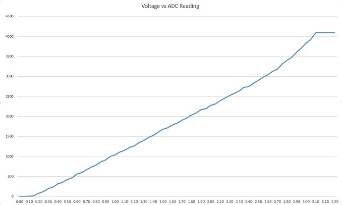
This development board supports 18 ADC channels. And each channel is of 12 bits. So it has a good resolution. It can be used to measure analog voltage, current and any analog sensor which provides output in the form of analog voltage. These ADCs can also be used in sleep mode for lower power consumption. Each ADC channel has a resolution of 12 bits which is equal to
3.3 / 4095 where 3.3 volt is a reference voltage and 4095 is minimum step by ADC
So the minimum voltage, we can measure with these ADC channels is about 80 microvolt. Anything less than this will be an error. I will talk more about it in coming tutorials. The major drawback of ESP32 ADC is that it has a nonlinear behavior. you can check the diagram below:
The mapping of Analog pins with GPIO pins is shown below:
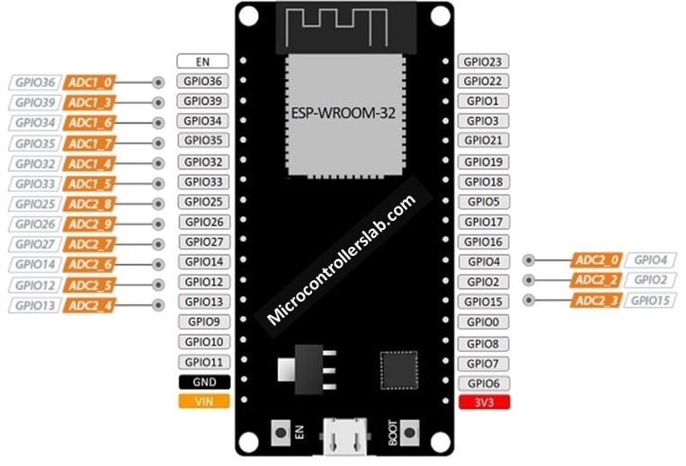
- ADC1_CH0 – GPIO36
- ADC1_CH1 – GPIO37
- ADC1_CH2 – GPIO38
- ADC1_CH3 – GPIO39
- ADC1_CH4 – GPIO32
- ADC1_CH5- GPIO33
- ADC1_CH6 – GPIO34
- ADC1_CH7 – GPIO35
- ADC2_CH0 – GPIO4
- ADC2_CH1 – GPIO0
- ADC2_CH2 – GPIO2
- ADC2_CH3 – GPIO15
- ADC2_CH4 – GPIO13
- ADC2_CH5 – GPIO12
- ADC2_CH6 – GPIO14
- ADC2_CH7 – GPIO27
- ADC2_CH8 – GPIO25
- ADC2_CH9 – GPIO26
Check this tutorial : How to use ADC of ESP32
Note: Not all Analog pins can be used when Wi-Fi is also being used. In our experience, ADC2_CH0 – GPIO4 does not work with WiFi being used. We recommend you to try each analog pin with Wi-Fi. It might be a design problem of EPS32. We are not sure if it is fixed in latest versions.
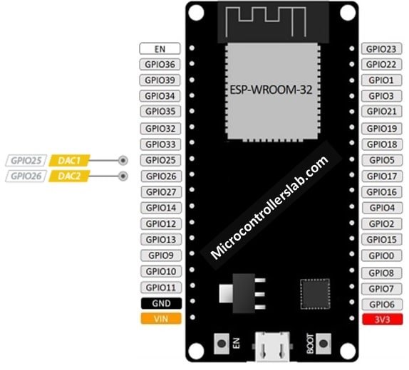
Digital to Analog converter pins
This development board has two onboard integrated 8-bit DAC. DACs are used to convert digital signals into analog signals. DACs have many applications like voltage control and PWM control.
- DAC_1 – GPIO25
- DAC_2 – GPIO26
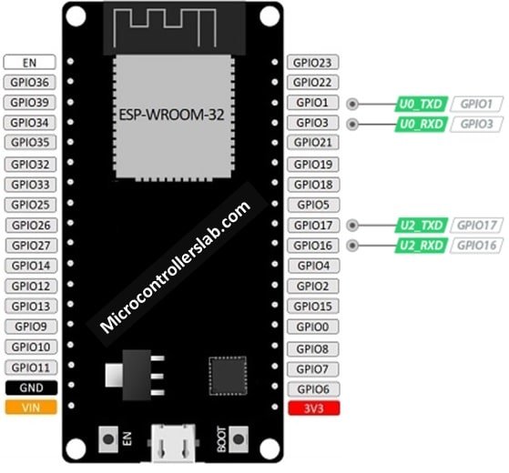
ESP32 UART Pins
According to the datasheet, ESP32 provides three universal asynchronous receivers and transmitter (UART) ports such as U0, U1, and U2. By default, only UART0 and UART2 can be used. To use UART1, we have to redefine the pins. Because default pins of UART1 such as GPIO9 and GPIO10 are internally connected to the SPI flash memory. Also, on some ESP32 boards, they are even exposed on the pinout headers. Hence, we can not use UART2 directly without reassigning pins in Arduino IDE.
| UART Port | Rx | Tx | Useable |
|---|---|---|---|
| UART0 | GPIO3 | GPIO1 | Yes |
| UART1 | GPIO9 | GPIO10 | Yes but require pins reassignment |
| UART2 | GPIO16 | GPIO17 | Yes |
Check this tutorial for more details:
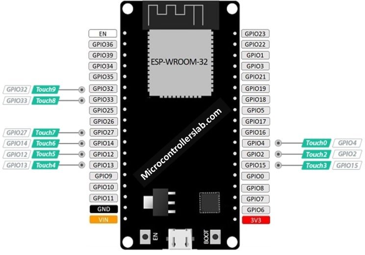
Touch sensor pins of Devkit
ESP-WROOM-32 provide onboard 10 capacitive touch sensors. So you don’t need to use separate touch sensors in your project when you are using this development board. These capacitive touch sensors can be used to detect any electrical and magnetic waves around like magnetic field detection. You can use a small array of pads instead of push buttons with these touch sensors.
- TOUCH0 – GPIO4
- TOUCH1 – GPIO0
- TOUCH2 – GPIO2
- TOUCH3 – GPIO15
- TOUCH4 – GPIO13
- TOUCH5 – GPIO12
- TOUCH6 – GPIO14
- TOUCH7 – GPIO27
- TOUCH8 – GPIO33
- TOUCH9 – GPIO32
How to use touch pins and how to use touch pins as a digital button?
Memory card interfacing pins
It also supports memory card interfacing through these pins.
- HS2_CLK – MTMS
- HS2_CMD – MTDO
- HS2_DATA0 – GPIO2
- HS2_DATA1 – GPIO4
- HS2_DATA2 – MTDI
- HS2_DATA3 – MTCK
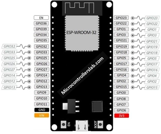
External interrupt pins
All general-purpose input output pins can be used as external interrupts. External interrupts are very useful. When you want to monitor change across any pin, you can use this pin as an interrupt instead of repeatedly monitoring the state of this pin.
PWM GPIO pins
All general-purpose input output pins can be used to generate PWM except digital input pins from GPIO pins 34-39. Because these pins cannot be used as digital output pins. PWM signals are digital output signals. The maximum frequency of these PWM pins is 80 MHz. you can configure any other pin as a PWM pin by following these steps:
- Select a frequency for pulse width modulation.
- Set the duty cycle or pulse width.
- Select the PWM channel. ESP32 provides 16 PWM channels.
- Assign a digital pin to select the PWM channel.
PWM motor control feature
It also supports motor control features through internal registers of the ESP32 chip. ESP32 supports two MCPWM units. These MCPWM units can be used to control motors directly. Each MCPWM has three pairs of outputs mentioned below. you just need to configure these registers with any GPIO pins. you can find more information about these registers in the datasheet. Registers names are given below:
- PWM1_OUT_IN0~2
- PWM0_FLT_IN0~2
- PWM1_FLT_IN0~2
- PWM0_CAP_IN0~2
- PWM1_CAP_IN0~2
- PWM0_SYNC_IN0~2
- PWM1_SYNC_IN0~2
You can attach the PWM signals to the GPIO pins to get output.
I2C communication pins
It has dedicated pins available for two-wire I2C communication. One pin is used for data transfer and another pin is used for clock synchronization.
- GPIO21 is SDA pin.
- GPIO22 is SCL pin.
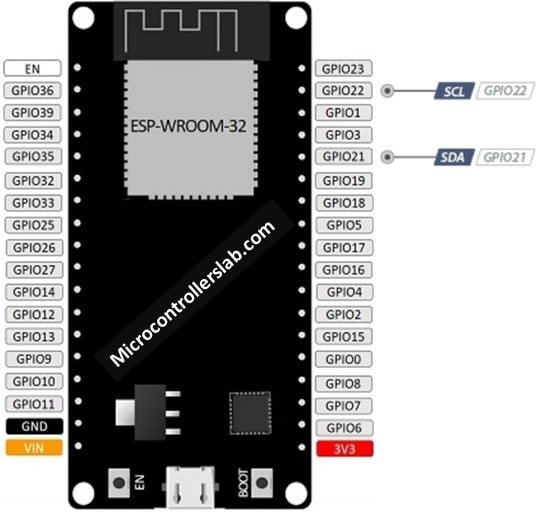
We have posted an article on I2C LCD interfacing with ESP32. This post explains how to I2C pins. you can read the complete article:
SPI Pins
By default, ESP32 has two SPI communication channels VSPI and HSPI and the following table provides the default SPI pins for both channels. But if we can also map these pins to other GPIO pins also in Arduino or esp-idf.
| SPI Channel | MOSI | MISO | SCK/CLK | CS/SS |
|---|---|---|---|---|
| VSPI | GPIO23 | GPIO19 | GPIO18 | GPIO15 |
| HSPI | GPIO13 | GPIO12 | GPIO14 | GPIO15 |
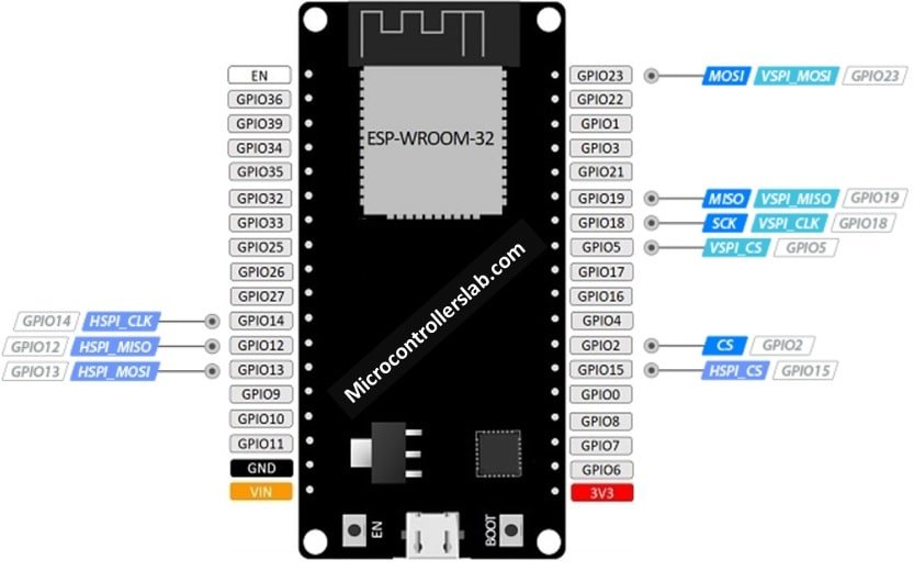
You can read this in-depth guide on ESP32 SPI communication:
RTC pins of ESP32 devkit
This board also provide RTC pins which can be used to trigger ESP32 from sleep mode.
- RTC_GPIO0 – GPIO36
- RTC_GPIO3 -GPIO39
- RTC_GPIO4 – GPIO34
- RTC_GPIO5 – GPIO35
- RTC_GPIO6 – GPIO25
- RTC_GPIO7 -GPIO26
- RTC_GPIO8 – GPIO33
- RTC_GPIO9 – GPIO32
- RTC_GPIO10 -GPIO4
- RTC_GPIO11 – GPIO0
- RTC_GPIO12 – GPIO2
- RTC_GPIO13 – GPIO15
- RTC_GPIO14 – GPIO13
- RTC_GPIO15 – GPIO12
- RTC_GPIO16 – GPIO14
- RTC_GPIO17 – GPIO27

Hall sensor pin
- A complete guide on How to use the built-in hall effect sensor of ESP32
It also has one hall sensor which is used to detect the magnetic field. Whenever you please this development board in the magnetic field, ESP32 generates a small voltage which can be measured with any pin. I will post a tutorial on it coming articles. Other features of the ESP32 development board and pins are shown in the above picture.
I2S (Inter-IC Sound)
ESP32 contains two I2S serial communication peripherals. I2S is used for Audio transmission and reception between two Audino devices. Each I2S controller works in a half-duplex communication mode. But we can combine these two available controllers to achieve full-duplex communication.
I2S -> GPIO25 and GPIO26 ( I2S can be directly connected with DAC output channels (GPIO25 and GPIO26) to get direct Audio analog output.
Pulse Counter Module (PCNT)
ESP32 has 8 pulse counter (PCNT) modules which are used to count the number of positive or negative edges of the signal given to the GPIO pins. Each pulse counter module consists of a 16-bits counter register which counts from 0 to 65536 on the positive or negative edge of an input signal. Moreover, it can also be configured to count-up and count-down mode based on the edges of an input signal. Most importantly, it provides a control pin to enable or disable the count from an input signal.
- All GPIO pins can be configured as an input signal for the pulse counter.
Remote Control Module
The remote control module driver can be used to transmit and receive IR remote control signals and any GPIO pin can be configured to receive and transmit IR signals.
Enable Pin
It also has an EN pin which can enable and disable ESP32 chip function. This pin is active high by default. When this pin is active high, the chip will be active and working and if this pin is active low, the chip will be disabled and not work at all. You can use enable button shown below:
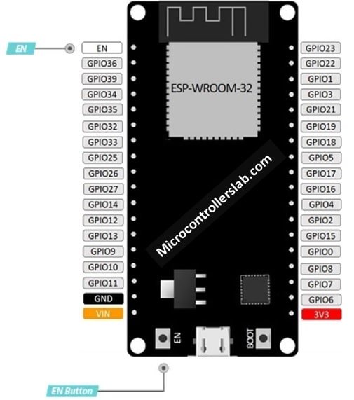
Automatically Resetting ESP32
This board has a 3.3V regulator enable pin with a pull-up resistor. This pin is connected to a push-button on the ESP32 board. Therefore, to automatically restart the board, connected this pin to the ground permanently.
If you liked this tutorial, you may also like to check these tutorials and projects:
- ESP32 tutorials and projects
- ESP32 Web server to control LEDs from the web page
- interfacing DHT11 DHT22 with ESP32 and displaying values on the webserver
- Displaying Images in ESP32 and ESP8266 Web Server
- Reconnect ESP32 to WIFI after Lost Connection (Solved)
- Use ESP32 Bluetooth Classic with Arduino IDE
- ESP32/ESP8266 Web Server to Control Outputs with a Timer (Pulse Width)
- Getting Current Date and Time with ESP32 using NTP Server-Client and Arduino IDE
- Save Data to ESP32 Flash Permanently using Preferences Library
- HTTP GET using ESP32 and Arduino IDE (OpenWeatherMap.org and ThingSpeak)
- ESP32 HTTP POST using Arduino IDE (ThingSpeak and IFTTT)