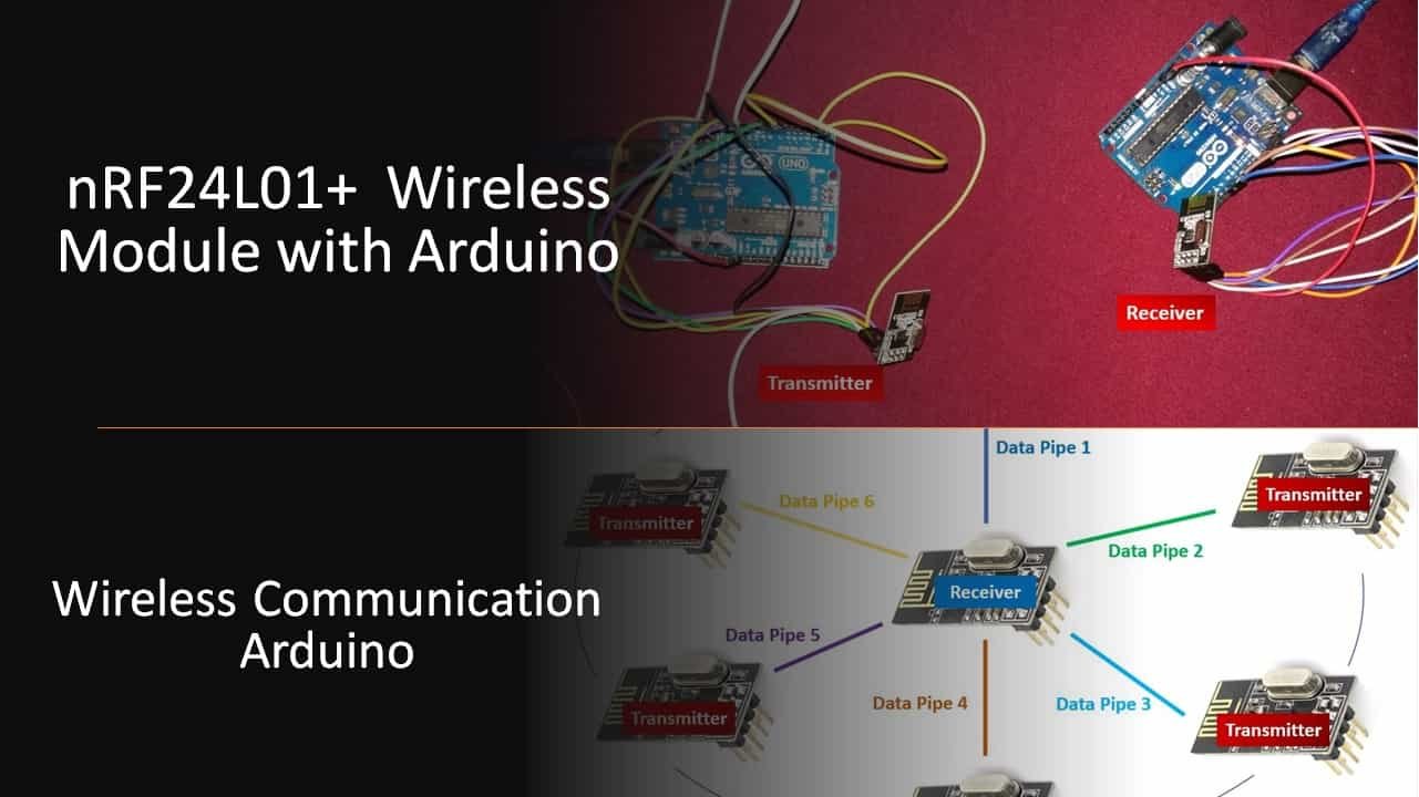
nRF24L01+ Wireless Module with Arduino ( Wireless Communication ) (original) (raw)
This in-depth guide focuses on nRF24L01+ wireless module, it’s working, and interfacing with Arduino. nF24L01+ is one of the legal RF communicators for modern applications. Its compact design and reliable nature make it a great option to be used in various projects that involve the wireless transmission of data over a distance. By the end of this guide, we will demonstrate two Arduino boards wirelessly transmitting/receiving data using nRF24L01.
Introducting nRF24L01+ Transceiver
nRF24L01 is the least expensive RF module and it comes with great features. A single module communicates at 2.4 GHz frequency which makes it legal. It can transmit and receive data by a single module. Acting as a transceiver is not its only ability, it can communicate with a total of 6 other same nRF24L01 modules at a single time. The device interfaces with the Arduino application and covers all kinds of remote-control applications. This wireless module uses SPI communication protocol and offers a 10MBs data rate with a 125 address range which makes it reliable the most reliable RF module. The RF module uses the GFSK module to transceiver the data. Let us learn all about this in detail.
Popular Versions
There are two common versions of nRF24L01+ available in the market.

- nRF24L01+ wireless module
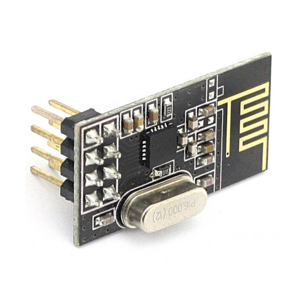
nRF24L01+ wireless module
The first version is small in size and already comes with an onboard antenna. It has a lesser transmission range, maximum of 100 meters.
- nRF24L01+ PA/LNA module

nRF24L01+ PA/LNA module
The second version comes with an external IPX antenna (with a power amplifier) which fits in the SMA connector. It has a higher cost than the first version due to the presence of the RFX2401C chip. This feature enables this module to cover a wider transmission range of approximately 1000m.
PA/LNA
PA is a power amplification of the RF band used for the transmission of a signal. LNA is low noise amplification which is generally used for higher RF bands. These two components act as important interfaces for wireless transmission between the internal circuitry and the antenna.

nRF24L01+ PA LNA Block Diagram
The antenna is connected with the duplexer which splits the transmitter and receiver side. A low noise amplifier also known as LNA is found on the receiver side and a power amplifier also known as PA is found on the transmitter path. Both of these signals pass through the duplexer that makes sure the powerful PA signal does not weigh down the sensitive LNA signal. The LNA makes sure that the weaker sensitive signal from the antenna gets amplified to a reasonable level via the PA through the RF system.
Notable Features
Let us briefly discuss some features possessed by the nRF24L01 wireless module.
Radio
The nRF240L01+ wireless module by Nordic semiconductors supports a 2.4 GHz worldwide ISM frequency band. It consists of 126 RF channels and has a common RX and TX interface. Data transmission is carried out through GFSSK modulation. Therefore an air data rate of 250kbps, 1Mbps, and 2Mbps is supported by this wireless module.
Transmitter & Power Management
The wireless module as a transmitter allows programmable output power of 0 dBm, -6 dBm, -12 dBm, and -18 dBm. Remarkably, it only takes up 11.3mA current at 0 dBm output power hence gaining the attribute for low-power consumption. Additionally, the module features idle modes (power down, Standby-I, and Standby-II mode) as well to facilitate good power management. This is enforced by very quick start-up times where the maximum start-up from power-down mode is 1.5ms and from standby-I mode is 130us.
Host Interface
This wireless module uses SPI communication protocol for the transmission of data. The maximum data transmission rate using this protocol is 10Mbps. The maximum number of nRF24L01 modules (that usually act as a slave where the microcontroller is the master) you can use with a single Arduino board is two. This is because the SPI protocol has a limitation of slaves. Additionally, this module features three distinct 32 bytes RX and TX FIFOs.
Take away Points
- nRF24L01+ wireless module is easily one of the most inexpensive wireless transceiver module available in the market bagging several useful features to its name.
- It works at 2.4GHz frequency which makes it legal in almost every country.
- A single module can act as both a transmitter or receiver.
- A built-in antenna can send the data up to 100 meters where the transmission distance significantly increases to 1000m if using the nRF240L01+ PA/LNA module instead.
- A module nRF24L01 can communicate with a maximum of 6 other modules at a time.
- It requires 3.3 volts to operate but voltages can only extend up to 3.6V otherwise it won’t take much time to heat up and burn.
- The device has a built-in oscillator of 16MHz.
- The transmission speed of nRF24L01 is 256kbps to 2Mbps.
- The device has 125 channel range which gives the feature of operating 125 different networks at a single place.
- The channel frequencies variate from 2400MHz to 2525MHz.
- Can easily be used with a number of microcontrollers that use SPI communication protocol. Moreover, it is very convenient to use with the widely used Arduino boards as the module has input pins that are 5V tolerant.
- This wireless module can be used in various applications. Some of these include :
- Creation of a small mesh network, nRF24L01 is the best choice to use.
- Remote control applications at developing and commercial works wonderfully with nRF24L01.
- Most IoT applications at home level have this wireless module at a small level.
Specifications
The following table briefly shows some key specifications of the nRF24L01+ wireless module:
| Supply Operating Voltage | 1.9 to 3.6V |
|---|---|
| Operating Temperature | -40 to +85 degree Celsius |
| Operating Frequency | 2400-2525 MHz |
| Maximum Output Power | +4 dBm |
| Maximum Operating Current | 13.5 mA |
| Maximum Air Data Rate | 2 Mb/s |
| Supply Current in Power-down Mode | 900 nA |
| Supply Current in Stand-by I mode | 26 uA |
How nRF24L01+ wireless module Works?
After learning some specifications and features of the nRF24L01+ wireless module let us see how exactly does the module work to transmit data.
RF Channels and Frequencies
We have already discussed how an nRF24L01+ transceiver supports the 2.4 GHz ISM frequency band which tells us that the operating frequency for this module to communicate with different nRF24L01+ modules is to operate between 2400-2525 MHz frequency range. This frequency is where the transceiver operates is also known as the RF channel. To enable different nRF24L01+ modules to communicate with each other they have to be present on the same channel or frequency. As the frequency range lies between 2400-2525 MHz and each corresponding channel has a spacing of approximately 1MHz (at 1Mbps air data rate) between them, hence a total of 125 operable channels may exist at a time.
This is shown in the figure below:

nRF240L01+ RF Channel Frequency
The following formula shows the relationship between the RF channel frequency and the RF channel:
RF Channel Frequency = 2400 + Selected Channel
For example, for channel 88, the RF channel frequency of this channel will be 2400 + 88 = 2488 MHz.
Multiple Transmitters Single Receiver Network
There are a bunch of applications nRF24L01 is useable but making a mesh is one of the best abilities of nRF24L01 which makes it different from another module.
One way to do that is to create a Multiple Transmitters Single Receiver (MultiCeiver) Network of the nRF24L01+ modules. One of the modules acts as the receiver obtaining data from 6 other transmitters at the same time. Each transmitter is connected to the receiver via a RF channel divided into 6 parallel data channels where a single one is known as a ‘Data Pipe.’ Here each data pipe has its own address.
The figure below shows a 6 data pipe MultiCeiver network:
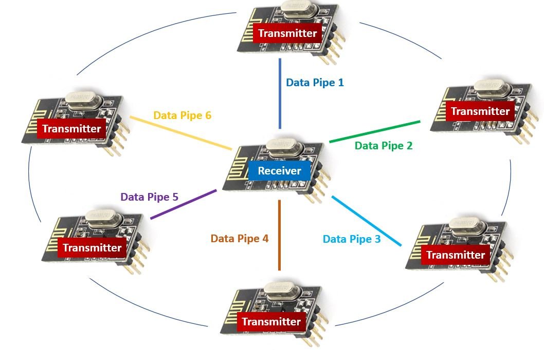
nRF240L01+ Multiceiver Network
Enhanced ShockBurst Protocol
The nRF240L01+ wireless transceivers use the enhanced ShockBurst protocol for the transmission/reception of data. It is a packet structure consisting of five separate fields known as Preamble, Address, Packet Control, Payload, and CRC (Cyclic Redundancy Check). The figure below shows a typical enhanced ShockBurst packet structure for nRF240L01+.
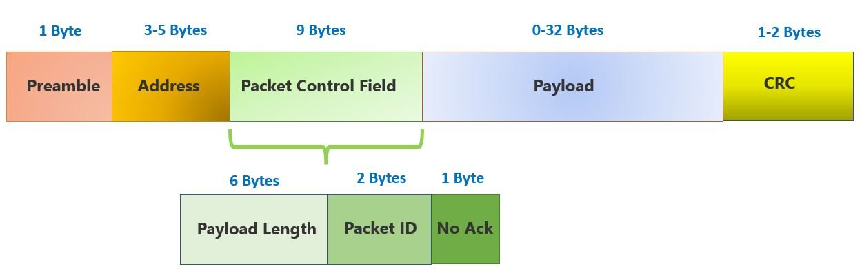
nRF24L01+ Enhanced ShockBurst Protocol packet structure
You may notice that the enhanced ShockBurst protocol contains an additional field of 9 bytes of Packet Control. This is an additional field added in the enhanced protocol. This field consists of three different subfields: 6 bytes of payload length, 2 bytes of packet ID, and 1 byte of No Ack. These all bring a great deal of efficacy for better communication between the modules.
1-32 bytes of dynamic payload length are now permitted with unique packet IDs for a packet that is sent to a receiver. This enables the receiver to easily distinguish between newly transmitted and retransmitted messages. Additionally, one very handy feature is the addition of acknowledgment messages. Here each message will be able to request an acknowledgment to be sent when it is received by another device. When a message with an ack payload is received, the nRF24L01+ module stores a preloaded message into its transmit FIFO buffer and sends the message to the listening pipe address.
Automatic Packet Handling
Another great feature of an nRF24L01+ enhanced ShockBurst protocol is the automatic packet handling. There are three ways in which the nRF24L01+ module carries out communication between another module via automatic packet handling. Let us discuss the scenarios:
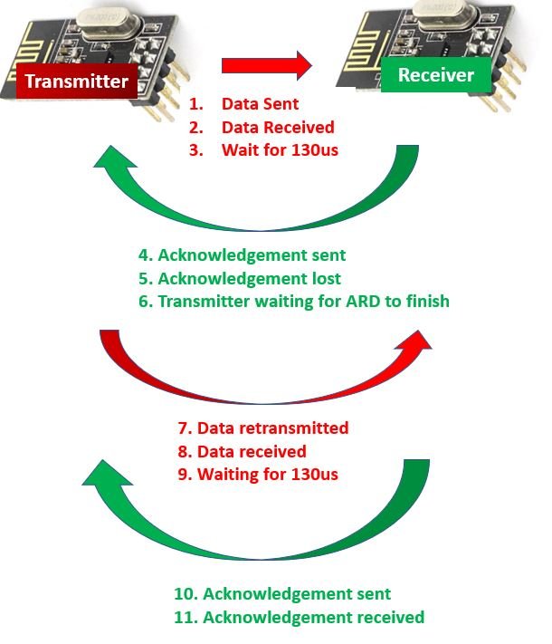
Data Transfer with acknowledgement and interrupt
This is the simplest case where data is sent from the transmitter to the receiver and gets received by the receiver. Then we have a wait for 130us for the acknowledgment packet to receive. After the receiver successfully obtains the message, it sends an acknowledgment message to the transmitter which is then received by it. The transmitter then generates an interrupt signal to denote the availability of new data packet.

Data Transfer with data packet lost
In this scenario, when the transmitter sends the data packet to the receiver, it gets lost before gets transmitted. In the meanwhile, the transmitter waits for the Auto-Retransmit-Delay also known as the ARD time to finish until it receives the acknowledgment message. If the acknowledgment message does not arrive within this time then the data pack is retransmitted to the receiver. After that, the retransmitted data gets received by the receiver which in turn sends the acknowledgment message after a wait of 130us. After the acknowledgment message is received by the transmitter, it creates the interrupt signal.

Data Transfer with acknowledgement lost
Now let us look at the case where the acknowledgment packet gets lost instead. Follow the diagram below to properly analyze the situation. Here the data is successfully received by the receiver but the acknowledgment packet gest lost. Therefore, the data packet is retransmitted as the transmitter did not receive an acknowledgment message. After the ARD time finishes, the data packet gets retransmitted. The receiver now receives the same data packet again, checks the packet ID, and abandons it. It then sends the acknowledgment message to the transmitter which then receives it and generates an interrupt signal for the next data packet transmission.
nRF24L01+ Module Pinout
In nRF24L01+ there aren’t any special pins, all pins it offers to communicate are present in all microcontrollers and boards. The device will interface with an external microcontroller/Arduino through these pins to operate. It consists of 8 pins. All available pins are:
| Pin Number | Name | Description |
|---|---|---|
| 1 | GND | nRF24L01+ operates with another microcontroller and it will need a common ground to operate with it. GND pin will solve the requirement of the common ground. |
| 2 | VCC | The power pin of the module is VCC (1.9-3.9V), which connects itself with the power supply. |
| 3 | CE | CE is the Chip Enable pin. It activates the transmission/receiving of the module. It will only activate the device when there is a HIGH state on itself. |
| 4 | CSN | This pin (Chip Select Not) is for activating the data listening and processing from the microcontroller. To keep the data communication between the microcontroller and the module it should be HIGH. |
| 5 | SCK | It is the clock pulse pin of SPI communication in nRF24L01+. The data will move between the module and the microcontroller according to the clock pulse on the SCK pin. |
| 6 | MOSI | Master Out Slave In pin, SPI input pin. |
| 7 | MISO | Master In Slave Out pin, SPI output pin. |
| 8 | IRQ | IRQ is an interrupt pin, which generates the event whenever new data is available for SPI pins. It helps to send feedback to the transmitter. |
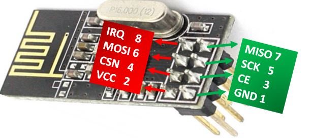
nRF240L01+ Pin Out
The nRF240L01+ PA/LNA module also has the same pin configurations as the nRF240L01+ wireless module we demonstrated above.
Interfacing nRF240L01+ Transmitter and Receiver with Arduino
Following components are required:
- Two Arduino UNO boards
- Two nRF240L01+ modules
- Connecting Wires
The connection diagram for the transmitter side and receiver side is the same. Follow the schematic diagram below to connect the two devices properly.

nRF240L01+ and Arduino UNO connection diagram
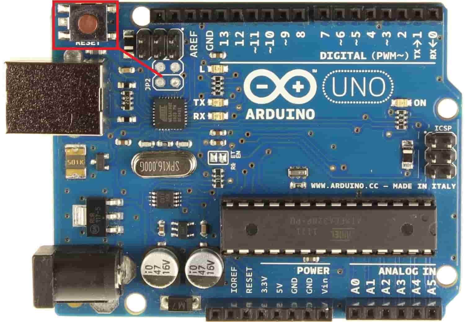
We have used the default SPI pins of Arduino UNO to connect with the SPI pins of the transceiver module. The diagram below shows the default SPI pins of Arduino UNO.
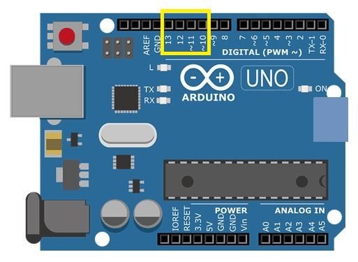
Arduino UNO SPI Pins
- Pin11 = MOSI
- Pin12 = MISO
- Pin13 = SCK
- Pin10 = SS
We have connected the SPI pins MOSI, MISO, and SCK of nRF24L01+ module with the respective SPI pins of Arduino UNO i.e. digital pin 11, pin 12, and pin 13 respectively. VCC pin and GND pin are connected with 3.3V and GND from Arduino respectively. Moreover, connect CE and CSN with any appropriate digital pin of the Arduino board. We have used digital pin 7 to connect with CE and digital pin 6 to connect with CSN.

You can also read this guide to know more about Arduino SPI communication:
Reducing Power Supply Noise
If powering the nRF24L01+ module using 3.3V from the Arduino board as shown in the connection diagram above then we could face some power supply noise issues. This will reduce the signal transmission range.
It is therefore recommended to use an nRF24L01 breakout power regulator module with the setup above. This module effectively step-downs the 5V input voltage and regulates it at 3.3V to power the wireless module. It easily connects with the nRF24L01+ wireless module via the male connectors.
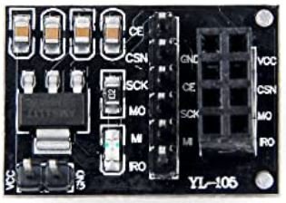
nRF24L01+ Breakout Adapter with On-board 3.3V Regulator
However, if you do not have access to this adapter then you should use a 10uF capacitor between the VCC and GND pins of the nRF24L01+ module. This will filter out and regulate the input voltage. Fluctuations will also be reduced.
Further ways to improve range of transmission
There are some other ways as well in which we can improve the range of our nRF24L01+ transceiver.
- Maximum Output Power: To enable a better range of transmission choose maximum power output of 0 dBm. The module itself supports programmable output power of 0 dBm, -6 dBm, -12 dBm and -18 dBm so better to choose maximum output power.
- Channel Frequency: Another aspect to keep in mind is the selection of channel frequency. It is always a better idea to use higher channels for your module as the lower channels are usually occupied and may pose as an interference for the radio frequency circuit.
- Lower Data Rate: A lower data rate is known to greatly increase the range of transmission. This is because lower data rates e.g. 250 Kbps speed has higher receiver sensitivity than higher data rates. The receiver is more sensitive at lower data levels thereby detecting a wider range of RF signals.
Installing RF24 Library
We will require the RF24 library to program our Arduino board with nRF24L01+ in Arduino IDE easily. This library provides us with adequate functions that unable a smooth and easy communication between devices.
This library is not available in the Arduino library manager so we will have to download and load it in the IDE ourselves. We will use GitHub to download the library and then place it in the library folder of our Arduino IDE.
Click RF24 library to open the respective GitHub page for the library.

Click the Code button and go to the Download Zip option as highlighted in the figure. Your zip file will get downloaded to your computer right away. After the download is complete, extract the .zip file to the Arduino library folder.
You can also go to Sketch > Include Library > Add .zip Library inside the IDE to add the library as well. Through this procedure now we will be able to use the functionalities of the library inside our Arduino IDE.
Arduino Sketch for nRF24L01+ Transmitter
Open your Arduino IDE and go to File > New. A new file will open. Copy the code given below in that file and save it.
This sketch will enable the nRF24L01+ module to act as a transmitter. It can only transmit data at a single channel to another module. We will transmit the message “Welcome” to the other module that will act as a receiver.
#include <SPI.h>
#include <nRF24L01.h>
#include <RF24.h>


RF24 radio(7, 6);  // CE, CSN


const byte address[6] = "00001";

void setup()
{
  radio.begin();

  //set the address
  radio.openWritingPipe(address);

  //Set module as transmitter
  radio.stopListening();
}
void loop()
{
  //Send message to receiver
  const char text[] = "Welcome";
  radio.write(&text, sizeof(text));

  delay(1000);
}
How the Code Works?
The first step is to include the necessary libraries required for this project.
#include <SPI.h>
#include <nRF24L01.h>
#include <RF24.h>
Next, we will create an object of R24 called radio() and pass the Arduino digital pins we have connected with CE and CSN as parameters inside it. The number 7 represents the CE pin and 6 represents the CSN pin. Both are changeable according to any digital pins; here they are according to the circuit we used above.
RF24 radio(7, 6); // CE, CSNThis is the byte variable that stores the address through which the two modules will communicate with each other. The address will be the same for both the transmitter and the receiver. The address is definable with 5 bits for the device at which it should communicate the receiver. Any 5-bits number is useable.
const byte address[6] = "00001";Inside the setup() function first we will initialize the wireless module using the begin() method on the radio object.
radio.begin();Then we will configure the address of the transmitter using the openWritingPipe() method.
radio.openWritingPipe(address);After that the module should know its mode: receiver or transmitter. The following line of code enables the nRF24L01+ module to be set up as a transmitter.
radio.stopListening();Inside the loop() function we will send the “Welcome” message to the receiver after every second. The write() method on the radio object will be responsible to send the data packet to the receiver. This takes in two parameters. The first parameter is the message and the second parameter is the size of the message.
Remember the transmitter can only send 32 bytes of data at a time because of module limitations.
void loop()
{
  const char text[] = "Welcome";
  radio.write(&text, sizeof(text));

  delay(1000);
}
Arduino Sketch for nRF24L01+ Receiver
Open your Arduino IDE and go to File > New. A new file will open. Copy the code given below in that file and save it.
This sketch will enable the nRF24L01+ module to act as a receiver. It can only receive data at a single channel with another module. We will receive the message “Welcome” from the other module that will act as a transmitter.
#include <SPI.h>
#include <nRF24L01.h>
#include <RF24.h>

RF24 radio(7, 6);  // CE, CSN

const byte address[6] = "00001";

void setup()
{
  while (!Serial);
    Serial.begin(115200);

  radio.begin();

  //set the address
  radio.openReadingPipe(0, address);

  //Set module as receiver
  radio.startListening();
}

void loop()
{
  if (radio.available())
  {
    char text[32] = {0};
    radio.read(&text, sizeof(text));
    Serial.println(text);
  }
}
How the Code Works?
Some parts of the code are different for the receiver module. Let us look at the relevant parts.
Inside the setup() function, we will first open the serial communication at a baud rate of 115200. The module will get initialized then we will start the communication between the receiver and transmitter by using the openReadingPipe() function. It takes in two parameters. The first part which is “0” defines the channel. The module offers 6 channels to communicate at a time, the first part of the programming will help to build multiple channels.
The second parameter is the address which defines the address of the transmission device. It is the same address that we used for the transmitter hence enabling both the devices to communicate with each other. After that, the module should know its mode: receiver or transmitter. The startListening() function enables the nRF24L01+ module to be set up as a receiver.
void setup()
{
  while (!Serial);
    Serial.begin(115200);

  radio.begin();
  radio.openReadingPipe(0, address);


  radio.startListening();
}
Inside the loop() function, if some data is available in the buffer then we will read it. The read() method on the radio object will be responsible to store the message sent by the transmitter in the array we defined. This takes in two parameters. The first parameter is the message and the second parameter is the size of the message. We will also print this message in our serial monitor.
void loop()
{
  if (radio.available())
  {
    char text[32] = {0};
    radio.read(&text, sizeof(text));
    Serial.println(text);
  }
}
Demonstration
Make sure you choose the correct board and COM port before uploading the codes to the respective boards.
Go to Tools > Board and select Arduino UNO. Next, go to Tools > Port and select the appropriate port through which your board is connected.

Click on the upload button to upload the code into the board.
After you have uploaded your code to the development board, press its RST button.
In your Arduino IDE, open up the serial monitor for the receiver side and you will be able to view the “Welcome” message that got transmitted by the module.

Serial Monitor
| Arduino Components | Amazon Links |
|---|---|
| Arduino Starter Kit | Buy Now |
| Arduino Development Kit | Buy Now |
| Arduino Smart Robot Car Kit V4 | Buy Now |
| Arduino Sensors Kit | Buy Now |