Temperature Sensor using PIC16F877A Microcontroller (original) (raw)
Temperature measurement is a crucial aspect in numerous applications, spanning from weather monitoring to industrial processes. The ability to accurately and efficiently measure temperature plays a vital role in ensuring the optimal performance and safety of various systems. In this article, we will explore the implementation of a digital temperature measurement system using a microcontroller. By utilizing components such as the PIC16F887A microcontroller, LM35 temperature sensor, and an LCD display, we will look into the circuitry, code, and practical aspects of this project.
Components
To build this system, we require the following components:
1. PIC16F877A Microcontroller
The PIC16F877A microcontroller is a powerful and easy-to-program 8-bit microcontroller. It features 256 bytes of EEPROM data memory and self-programming capabilities. The operating voltage range is between 2V and 5.5V, making it versatile for various projects. It also includes 2 comparators, a 10-bit Analog-to-Digital Converter (ADC), and PWM functions, making it suitable for interfacing with LCDs and sensors.

2. Pickit 3 Programmer
To program the PIC16F877A microcontroller, we require a Pickit 3 programmer. This programmer is compatible with the MPLAB Integrated Programmer Environment (IPE) and allows for easy programming of the microcontroller.
3. LCD 16×2 Display
A 16×2 LCD display is used to show the temperature readings. It consists of 16 pins and requires a 10K ohm potentiometer to adjust the contrast. The display also includes a backlight LED. The LCD is capable of displaying 16 characters in two lines, providing sufficient space for temperature display.
4. LM35 Temperature Sensor
The LM35 is an inexpensive yet precise temperature sensor. It has a temperature measurement range between -50°C to 150°C and operates from 4V to 30V, consuming less than 60μA current. Compared to other temperature sensors, the LM35 is more efficient, as it is made up of an integrated circuit with no risk of damaging internal circuitry. Additionally, it draws current only in micro Amperes, making it ideal for portable projects.
Others
Other components required for this project include a breadboard, jumper wires, and a 10K ohm potentiometer.
LM35 Temperature Sensor Interfacing with Pic Microcontroller
The LM35 temperature sensor converts temperature into an analog voltage value. Pin one and three of the LM35 are connected to the 5-volt power supply, whereas pin two outputs the analog voltage proportional to the temperature value. The relationship between the measured temperature and the analog output voltage is 1°C = 10mV.
To measure the analog voltage value, we use the PIC16F887A microcontroller’s built-in ADC. The microcontroller has seven built-in ADC channels, allowing for easy interfacing with multiple sensors. After reading the ADC value, the voltage is converted back into temperature using a conversion factor. The temperature value is then displayed on the LCD, which is connected to PORTB of the microcontroller.
Circuit Diagram
The circuit diagram for the digital temperature sensor is shown below:
The circuit diagram illustrates how the components, including the PIC16F877A microcontroller, LM35 temperature sensor, and LCD display, are interconnected to form a complete temperature measurement system. By using the microcontroller’s analog-to-digital converter (ADC) to read the voltage from the LM35 temperature sensor and utilizing specific code, the temperature value can be converted and displayed on the LCD screen.
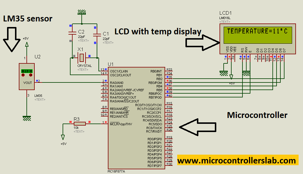
To protect the LM35 and microcontroller, it is recommended to connect an 80K ohm resistor in parallel to the output of the temperature sensor.
NOTE: Before starting this project, it is recommended to learn about LCD interfacing with a Pic microcontroller, especially the hardware part. Understanding this will help avoid any issues during the project implementation.
Code
The code for this project is written in the MIKROC compiler. It includes sections for reading the temperature, converting the data, and displaying it on the LCD. If you do not know how to use MikroC for Pic, you can refer to these tutorials:
- How to Use “MikroC PRO for PIC” to Program PIC Microcontrollers
- Pic microcontroller programming in c using Mikroc Pro for PIC
In programming part conversion factor is used to convert voltage back into temperature.The conversion factor is:
- 1 volt = 100 degree
- temp = ( Output voltage * 100 oC/V )
- Code is written in MIKRO C compiler.
// LCD module connections
sbit LCD_D7 at RB2_bit;
sbit LCD_D6 at RB3_bit;
sbit LCD_D5 at RB4_bit;
sbit LCD_D4 at RB5_bit;
sbit LCD_EN at RB6_bit;
sbit LCD_RS at RB7_bit;

sbit LCD_D7_Direction at TRISB2_bit;
sbit LCD_D6_Direction at TRISB3_bit;
sbit LCD_D5_Direction at TRISB4_bit;
sbit LCD_D4_Direction at TRISB5_bit;
sbit LCD_EN_Direction at TRISB6_bit;
sbit LCD_RS_Direction at TRISB7_bit;

int temp;
char temper[7];

void READ_temp(void)
{
    temp = ADC_Read(0);
    temp = temp * 5/1023;
    temp = temp * 100;
}

void data_conversion(void)
{
    inttostr(temp, temper);
}

void display_temperature(void)
{
    lcd_out(1, 1, "TEMPERATURE=");
    lcd_out(1, 13, Ltrim(temper));
    Lcd_Chr_Cp(0xdf);
    Lcd_Chr_Cp('C');
    Lcd_Chr_Cp(' ');
}

void main()
{
    ADC_Init();
    Lcd_Init(); // Initialize LCD
    Lcd_Cmd(_LCD_CLEAR); // Clear display
    lcd_cmd(_LCD_CURSOR_OFF);
    lcd_out(1, 4, "DIGITAL TEMPERATURE");
    lcd_out(2, 6, "SENSOR");
    delay_ms(1000);
    Lcd_Cmd(_LCD_CLEAR); // Clear display

    while(1)
    {
        READ_temp();
        data_conversion();
        display_temperature();
    }
}
How Does Code Work?
Here’s an explanation of each line of code:
// LCD module connections
sbit LCD_D7 at RB2_bit;
sbit LCD_D6 at RB3_bit;
sbit LCD_D5 at RB4_bit;
sbit LCD_D4 at RB5_bit;
sbit LCD_EN at RB6_bit;
sbit LCD_RS at RB7_bit;

sbit LCD_D7_Direction at TRISB2_bit;
sbit LCD_D6_Direction at TRISB3_bit;
sbit LCD_D5_Direction at TRISB4_bit;
sbit LCD_D4_Direction at TRISB5_bit;
sbit LCD_EN_Direction at TRISB6_bit;
sbit LCD_RS_Direction at TRISB7_bit;
These lines define the connections between the PIC microcontroller and the LCD module. The sbit keyword is used to define individual bits of the microcontroller’s ports (RB2, RB3, RB4, RB5, RB6, RB7) as corresponding pins of the LCD module. The sbit LCD_D7_Direction at TRISB2_bit; lines set the direction of the LCD pins as output.
int temp;
char temper[7];
Here, two variables are declared: temp to store the temperature value and temper, an array of characters to store the converted temperature value.
void READ_temp(void)
{
    temp = ADC_Read(0);
    temp = temp * 5/1023;
    temp = temp * 100;
}
This function reads the temperature value from the ADC (Analog-to-Digital Converter) channel 0. The ADC_Read(0) function returns a value in the range of 0 to 1023, which represents the analog voltage value. The temp value is then converted to temperature by multiplying it with a conversion factor.
void data_conversion(void)
{
    inttostr(temp, temper);
}
This function converts the integer temperature value (temp) into a string format (temper) using the inttostr() function. It enables the temperature value to be displayed on the LCD.
void display_temperature(void)
{
    lcd_out(1, 1, "TEMPERATURE=");
    lcd_out(1, 13, Ltrim(temper));
    Lcd_Chr_Cp(0xdf);
    Lcd_Chr_Cp('C');
    Lcd_Chr_Cp(' ');
}
This function displays the temperature value on the LCD. The lcd_out() function is used to output the string “TEMPERATURE=” at the specified position on the LCD (line 1, column 1). The Ltrim() function is used to remove any leading spaces from the temper string. The Lcd_Chr_Cp() function is used to display the degree symbol (0xdf) followed by the letter ‘C’ on the LCD.
void main()
{
    ADC_Init();
    Lcd_Init(); // Initialize LCD
    Lcd_Cmd(_LCD_CLEAR); // Clear display
    lcd_cmd(_LCD_CURSOR_OFF);
    lcd_out(1, 4, "DIGITAL TEMPERATURE");
    lcd_out(2, 6, "SENSOR");
    delay_ms(1000);
    Lcd_Cmd(_LCD_CLEAR); // Clear display

    while(1)
    {
        READ_temp();
        data_conversion();
        display_temperature();
    }
}
The main() function is the entry point of the program. It initializes the ADC and LCD by calling the ADC_Init() and Lcd_Init() functions, respectively. The Lcd_Cmd(_LCD_CLEAR) function is used to clear the LCD display. The lcd_cmd(_LCD_CURSOR_OFF) turns off the cursor on the LCD. The lcd_out() functions are used to output the specified strings on the LCD. After a brief delay, the while loop starts, continuously reading the temperature, converting it, and displaying it on the LCD.
Demonstration
To fully simulate and obtain the hex file for this project, please refer to the following link: Temperature Sensor using PIC Microcontroller.
Conclusion
Implementing a digital temperature measurement system using a microcontroller provides a cost-effective and accurate solution. By utilizing the LM35 temperature sensor and the PIC16F887A microcontroller, it is possible to measure and display temperature readings with ease.
You may also like to read: