Configuration of EByte RF E70 Module (esp32, STM32, Arduino, Raspberry Pi Pico) (original) (raw)
The EByte RF E70 module stands out in the realm of wireless communication, offering a unique blend of long-range capability and low power consumption. Ideal for IoT applications, this module has gained popularity among developers and hobbyists alike. This article aims to guide you through the essential steps to configure the EByte RF E70 module for your specific needs.
Configuration of EByte RF E70 Module (esp32, esp8266, STM32, Arduino, Raspberry Pi Pico)
Toggle
- Understanding the EByte RF E70 Module
- E70 modality
- Pinout E70 xxxT14S2
- Use a UART device with the EByte program.
- Library installation
- Using the library
- Set the configuration
- Thanks
Understanding the EByte RF E70 Module
Before diving into the configuration, it’s important to understand the features of the E70 module. It operates in the sub-gigahertz frequency bands, allowing extended-range communication. The module also supports various modes, including continuous and sub-packet modes, and adjustable parameters like frequency, power output, and data rate.
Here the RF devices E70 433/915 T S/S2 - E70 433/915 MT S
E70 modality
You can find all kinds of wiring diagrams in the previous articles of the series.
As you can see, I also connect the M0, M1, and M2, but these are unnecessary; you can select an operation modality by setting these values to those pins.
| Mode (0-7) | M2 | M1 | M0 | Mode introduction | Remark |
|---|---|---|---|---|---|
| 0 RSSI mode | 0 | 0 | 0 | Module outputs RSSI value each 100ms through UART. | The air data rate can be adjusted automatically according to the baud rate. The baud rate must be the same on both the receiver and transmitter. It is applicable for high-speed continuous data transmission. |
| 1 Continuous mode | 0 | 0 | 1 | UART opens. Wireless closes, and sub-package transparent transmission is available. | UART opens. Wireless closes, and continuous transparent transmission is available. |
| 2 Sub-package mode | 0 | 1 | 0 | UART opens. Wireless closes, and parameters can be configured. | Air data rate and baud rate can be adjusted separately. It is applicable for data packet transmission. |
| 3 Configuration mode | 0 | 1 | 1 | The baud rate is fixed as 9600 8N1. | UART opens. Wireless closes, and subpackage transparent transmission is available. |
| 4 WOR mode | 1 | 0 | 0 | Transmission is not available under this mode. It can be woken up by a transmitter under mode 4 to achieve low power consumption receiving. | Receiving is not available under this mode. Preamble code will be added proactively before transmission to wake up the receiver under mode 6. |
| 5 Configuration mode (Same as Mode 3) | 1 | 0 | 1 | – | – |
| 6 Power saving mode | 1 | 1 | 0 | Any M2, M1, or M0 falling edge can wake it up. | UART closes. Wireless works at WOR power saving mode. Multiple-time grades can be configured. |
| 7 Sleep mode | 1 | 1 | 1 | Any falling edge of M2, M1, or M0 can wake it up. | UART closes, wireless transmitting is available, and sleep mode is on. |
For this experiment, you must set the devices in sub-packet mode.
- M0: HIGH
- M1: HIGH
- M2: LOW
Pinout E70 xxxT14S2
For my test, I’m going to use an E70 S2 version because It’s a comfortable form factor with an onboard SMA antenna.
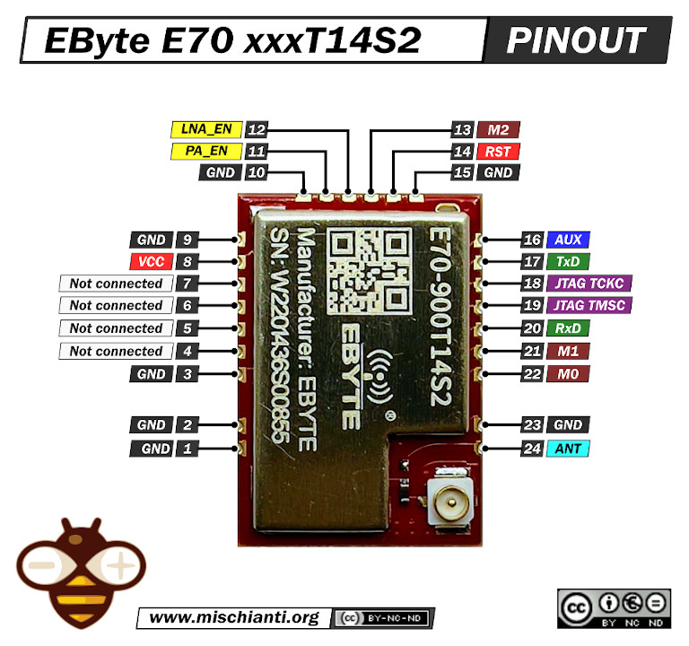
EByte E70 400/433/868/900/915 T14S2 pinout
3D printed socket for breadboard
I created a simple socket with my 3D printer to quickly prototype (and manage) the E70 S2; here is the 3D model and the result on a breadboard.
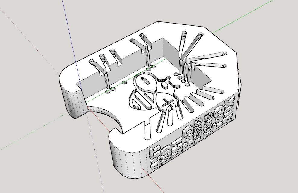
EByte E70 xxxT14S2 socket 3d printed for breadboard
It’s very simple and uses the same technique as other sockets I already created.
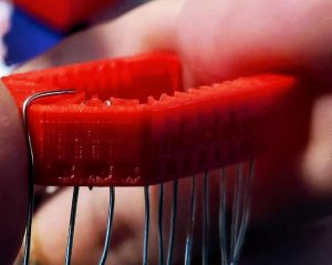
After printing, you must add writing inside the hole.
Insert it into the innermost holes and push it out about 3mm
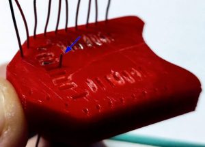
esp12 socket breadboard adapter step 1
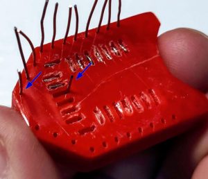
Bend the wire to the external of the adapter.
esp12 socket breadboard adapter step 2
Cut the external part of the wire, and extract,

esp12 socket breadboard adapter step 3
then reinsert in the internal and external holes.
esp12 socket breadboard adapter step 4
Now check if you need to cut more of the wire of the internal hole and bend It.
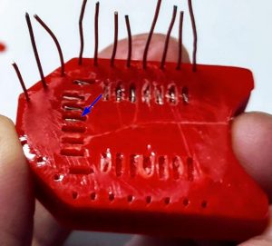
esp12 socket breadboard adapter step 5
Repeat for all pins. The result It’s very satisfying.
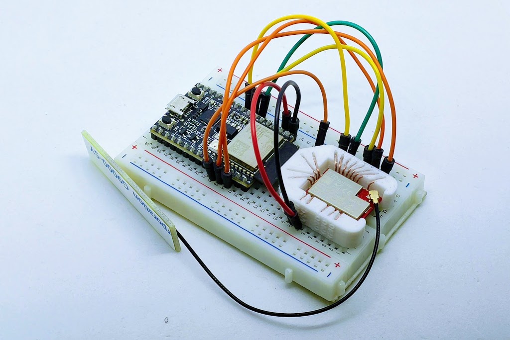
EByte E70 433T14S2 breadboard with socket adapter
Use a UART device with the EByte program.
The RF Setting program provided by EByte is a specialized software tool designed to configure devices, such as the EByte RF E70 module. This program allows users to customize various parameters and settings related to the radio frequency (RF) communication of the device. Here’s a technical description of its key features and functionalities:
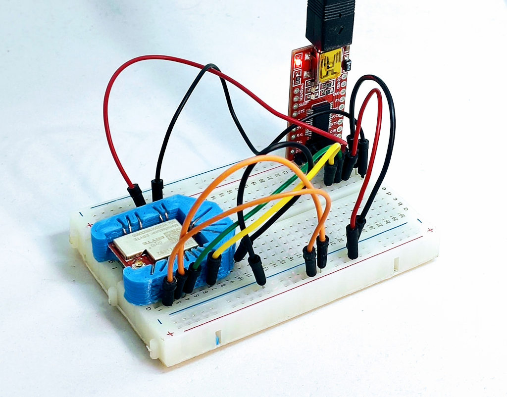
PC USB RF Settings E70 on breadboard wiring
- Frequency Configuration: One of the primary functions is to set the operating frequency of the device. This includes selecting the specific frequency bands that are compliant with regional regulations (e.g., 868 MHz for Europe, 915 MHz for North America).
- Transmission Power Control: Users can adjust the transmission power level of the device. This is crucial for managing the range and energy consumption of the device.
- Modulation and Bandwidth Settings: The software allows for the adjustment of modulation parameters, including bandwidth, spreading factor, and coding rate. These settings are essential for balancing data rate, range, and resistance to interference.
- Network Settings: You can specify the Address and Channel.
- Firmware Update and Management: The software may also facilitate firmware updates for the module, ensuring the device operates with the latest features and security patches.
- Diagnostics and Testing: Tools for diagnosing and testing the RF performance of the device, including signal strength indicators and transmission tests, are typically included.
- Saving and Loading Configurations: Users can save their configurations and load them later, making it easier to manage multiple devices or restore settings.
The RF Setting program is an essential tool for developers and engineers working with RF technology, providing a comprehensive and accessible means to tailor the performance of their RF devices to specific application needs.
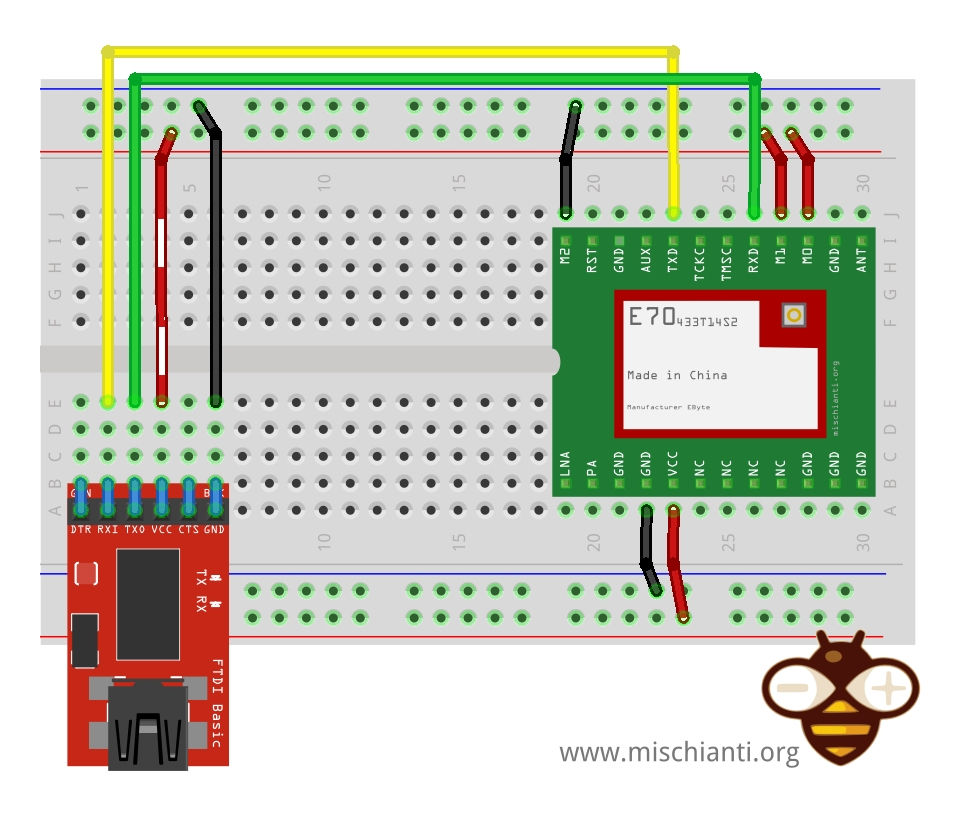
RF E70 EByte Serial wiring RF Settings
You can use the EByte program that I share also in the GitHub repository here.
The program is designed to connect with the RF device via a USB-to-serial interface or directly through a microcontroller’s serial port. For modules like the E70, a breadboard and jumper wires are often used for physical connections.
When you attach the RFSettings program and get the parameter, you have a screen like this.
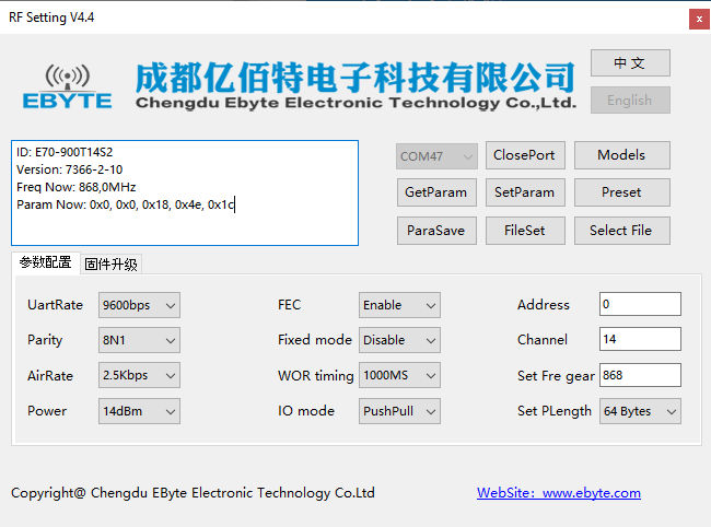
RFSettings of EByte RF E70 900T14S2
Library installation
You can find the library on GitHub.
But for simplicity, I added it to the Arduino Library manager.
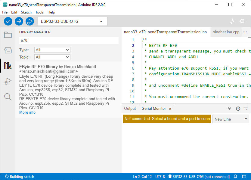
Arduino IDE installation of EByte RF E70 from the library manager.
Using the library
I create some examples to manage the configuration.
Retrieve configuration
To retrieve the configuration, you can use the function
ResponseStructContainer getConfiguration();That returns a ResponseStructContainer with inside the Configuration class.
struct Speed { uint8_t airDataRate :3; //bit 0-2 String getAirDataRateDescription() { return getAirDataRateDescriptionByParams(this->airDataRate); }
uint8_t uartBaudRate :3; //bit 3-5
String getUARTBaudRateDescription() {
    return getUARTBaudRateDescriptionByParams(this->uartBaudRate);
}

uint8_t uartParity :2; //bit 6-7
String getUARTParityDescription() {
    return getUARTParityDescriptionByParams(this->uartParity);
}
};
struct Option { uint8_t transmissionPower :2; //bit 0-1 String getTransmissionPowerDescription() { return getTransmissionPowerDescriptionByParams(this->transmissionPower); }
byte ioDriveMode  		: 1; //bit 2
String getIODroveModeDescription() {
    return getIODriveModeDescriptionDescriptionByParams(this->ioDriveMode);
}

byte fec       		: 1; //bit 3
String getFECDescription() {
    return getFECDescriptionByParams(this->fec);
}


byte wirelessWakeupTime : 3; //bit 4-6
String getWirelessWakeUPTimeDescription() {
    return getWirelessWakeUPTimeDescriptionByParams(this->wirelessWakeupTime);
}

byte fixedTransmission :1; //bit 7
String getFixedTransmissionDescription() {
    return getFixedTransmissionDescriptionByParams(this->fixedTransmission);
}
};
struct Channel { uint8_t CHAN :5; // bit 0-4 String getChannelDescription( ) { return String(this->CHAN + OPERATING_FREQUENCY) + F("MHz"); }
uint8_t subPacketSetting :3; //bit 5-7
String getSubPacketSetting() {
    return getSubPacketSettingByParams(this->subPacketSetting);
}
};
struct Configuration { byte COMMAND = 0;
byte ADDH = 0;
byte ADDL = 0;

struct Speed SPED;
struct Channel CHAN;

struct Option OPTION;
};
You can see that I also put some functions to get the description of the parameter.
/*
- RF E70
- Get configuration.
- You must uncommend the correct constructor.
- by Renzo Mischianti https://www.mischianti.org
- https://www.mischianti.org
- E70 ----- WeMos D1 mini ----- esp32 ----- Arduino Nano 33 IoT ----- Arduino MKR ----- Raspberry Pi Pico ----- stm32 ----- ArduinoUNO
- M0 ----- D6 ----- 23 ----- 4 ----- 2 ----- 9 ----- PB0 ----- 8 Volt div
- M1 ----- D7 ----- 19 ----- 5 ----- 3 ----- 10 ----- PB1 ----- 7 Volt div
- M1 ----- D8 ----- 22 ----- 6 ----- 4 ----- 11 ----- PB10 ----- 6 Volt div
- TX ----- D3 (PullUP) ----- TX2 (PullUP) ----- TX1 (PullUP) ----- 14 (PullUP) ----- 8 (PullUP) ----- PA2 TX2 (PullUP) ----- 4 (PullUP)
- RX ----- D4 (PullUP) ----- RX2 (PullUP) ----- RX1 (PullUP) ----- 13 (PullUP) ----- 9 (PullUP) ----- PA3 RX2 (PullUP) ----- 5 Volt div (PullUP)
- AUX ----- D5 (PullUP) ----- 18 (PullUP) ----- 2 (PullUP) ----- 0 (PullUP) ----- 2 (PullUP) ----- PA0 (PullUP) ----- 3 (PullUP)
- VCC ----- 3.3v/5v ----- 3.3v/5v ----- 3.3v/5v ----- 3.3v/5v ----- 3.3v/5v ----- 3.3v/5v ----- 3.3v/5v
- GND ----- GND ----- GND ----- GND ----- GND ----- GND ----- GND ----- GND
- Configuration can be emulated by set
- M0 = HIGH
- M1 = HIGH
- M2 = LOW
- */
#include "Arduino.h" #include "RF_E70.h"
// ---------- esp8266 pins -------------- //RF_E70 e70ttl(RX, TX, AUX, M0, M1, M2); // Arduino RX <-- e70 TX, Arduino TX --> e70 RX //RF_E70 e70ttl(D3, D4, D5, D7, D6, D7); // Arduino RX <-- e70 TX, Arduino TX --> e70 RX AUX M0 M1 //RF_E70 e70ttl(D2, D3); // Config without connect AUX and M0 M1
//#include <SoftwareSerial.h> //SoftwareSerial mySerial(D2, D3); // Arduino RX <-- e70 TX, Arduino TX --> e70 RX //RF_E70 e70ttl(&mySerial, D5, D6, D7, D8); // AUX M0 M1 // -------------------------------------
// ---------- Arduino pins -------------- //RF_E70 e70ttl(4, 5, 3, 8, 7, 6); // Arduino RX <-- e70 TX, Arduino TX --> e70 RX AUX M0 M1 //RF_E70 e70ttl(4, 5); // Config without connect AUX and M0 M1
//#include <SoftwareSerial.h> //SoftwareSerial mySerial(4, 5); // Arduino RX <-- e70 TX, Arduino TX --> e70 RX //RF_E70 e70ttl(&mySerial, 3, 8, 7, 6); // AUX M0 M1 // -------------------------------------
// ------------- Arduino Nano 33 IoT ------------- // RF_E70 e70ttl(&Serial1, 2, 4, 5, 6); // RX AUX M0 M1 // -------------------------------------------------
// ------------- Arduino MKR WiFi 1010 ------------- // RF_E70 e70ttl(&Serial1, 0, 2, 3, 4); // RX AUX M0 M1 // -------------------------------------------------
// ---------- esp32c3 pins -------------- // RF_E70 e70ttl(&Serial1, 1, 2, 3, 4,); // RX AUX M0 M1
RF_E70 e70ttl(4, 5, &Serial1, 6, 1, 2, 3, UART_BPS_RATE_9600); // esp32 RX <-- e70 TX, esp32 TX --> e70 RX AUX M0 M1 // -------------------------------------
// ---------- esp32 pins -------------- // RF_E70 e70ttl(&Serial2, 15, 23, 19, 22); // RX AUX M0 M1
//RF_E70 e70ttl(&Serial2, 22, 4, 18, 21, 19, UART_BPS_RATE_9600); // esp32 RX <-- e70 TX, esp32 TX --> e70 RX AUX M0 M1 // -------------------------------------
// ---------- Raspberry PI Pico pins -------------- // RF_E70 e70ttl(&Serial2, 2, 10, 11, 12); // RX AUX M0 M1 // -------------------------------------
// ---------------- STM32 -------------------- // HardwareSerial Serial2(USART2); // PA3 (RX) PA2 (TX) // RF_E70 e70ttl(&Serial2, PA0, PB0, PB1, PB10); // RX AUX M0 M1 // -------------------------------------------------
void printParameters(struct Configuration configuration); void printModuleInformation(struct ModuleInformation moduleInformation);
void setup() { Serial.begin(9600); #if defined(ARDUINO_ARCH_STM32) || defined(STM32F1) || defined(STM32F4) Serial.dtr(false); #endif
while(!Serial){};
delay(500);

Serial.println("INIT!!");

// Startup all pins and UART
e70ttl.begin();

ResponseStructContainer c;
c = e70ttl.getConfiguration();
// It's important get configuration pointer before all other operation
Configuration configuration = *(Configuration*) c.data;
Serial.println(c.status.getResponseDescription());
Serial.println(c.status.code);

printParameters(configuration);

ResponseStructContainer cMi;
cMi = e70ttl.getModuleInformation();
// It's important get information pointer before all other operation
ModuleInformation mi = *(ModuleInformation*)cMi.data;

Serial.println(cMi.status.getResponseDescription());
Serial.println(cMi.status.code);

printModuleInformation(mi);

c.close();
cMi.close();
}
void loop() {
} void printParameters(struct Configuration configuration) { Serial.println("----------------------------------------");
Serial.print(F("Configuration packet: "));
byte* byteArray = (byte*)&configuration;  // Cast the address of config to a byte pointer
for (int i = 0; i < sizeof(Configuration); i++) {
    if (byteArray[i] < 16) {
        Serial.print('0');  // Print a leading zero for single-digit hex values
    }
    Serial.print(byteArray[i], HEX);  // Print each byte of the struct in hexadecimal
    Serial.print(" ");
}
Serial.println(F(" "));

Serial.print(F("HEAD : "));  Serial.print(configuration.COMMAND, HEX);Serial.print(" ");
Serial.println(F(" "));
Serial.print(F("AddH : "));  Serial.println(configuration.ADDH, HEX);
Serial.print(F("AddL : "));  Serial.println(configuration.ADDL, HEX);
Serial.println(F(" "));
Serial.print(F("Chan : "));  Serial.print(configuration.CHAN.CHAN, DEC); Serial.print(" -> "); Serial.println(configuration.CHAN.getChannelDescription());
Serial.println(F(" "));
Serial.print(F("SpeedParityBit     : "));  Serial.print(configuration.SPED.uartParity, BIN);Serial.print(" -> "); Serial.println(configuration.SPED.getUARTParityDescription());
Serial.print(F("SpeedUARTDatte     : "));  Serial.print(configuration.SPED.uartBaudRate, BIN);Serial.print(" -> "); Serial.println(configuration.SPED.getUARTBaudRateDescription());
Serial.print(F("SpeedAirDataRate   : "));  Serial.print(configuration.SPED.airDataRate, BIN);Serial.print(" -> "); Serial.println(configuration.SPED.getAirDataRateDescription());
Serial.println(F(" "));
Serial.print(F("OptionFECPacketSett: "));  Serial.print(configuration.OPTION.fec, BIN);Serial.print(" -> "); Serial.println(configuration.OPTION.getFECDescription());
Serial.print(F("OptionTranPower    : "));  Serial.print(configuration.OPTION.transmissionPower, BIN);Serial.print(" -> "); Serial.println(configuration.OPTION.getTransmissionPowerDescription());
Serial.print(F("OptionIODrive: "));  Serial.print(configuration.OPTION.ioDriveMode, BIN);Serial.print(" -> "); Serial.println(configuration.OPTION.getIODroveModeDescription());
Serial.print(F("OptionFixedTransmission: "));  Serial.print(configuration.OPTION.fixedTransmission, BIN);Serial.print(" -> "); Serial.println(configuration.OPTION.getFixedTransmissionDescription());
Serial.print(F("OptionWirelessWakeUPTime: "));  Serial.print(configuration.OPTION.wirelessWakeupTime, BIN);Serial.print(" -> "); Serial.println(configuration.OPTION.getWirelessWakeUPTimeDescription());


Serial.println("----------------------------------------");
} void printModuleInformation(struct ModuleInformation moduleInformation) { Serial.println("----------------------------------------"); Serial.print(F("HEAD: ")); Serial.print(moduleInformation.COMMAND, HEX);Serial.print(" ");
Serial.print(F("Model no.: "));  Serial.println(moduleInformation.model, HEX);
Serial.print(F("Version  : "));  Serial.println(moduleInformation.version, HEX);
Serial.print(F("Features : "));  Serial.println(moduleInformation.features1, HEX);
Serial.print(F("Features : "));  Serial.println(moduleInformation.features2, HEX);
Serial.print(F("Features : "));  Serial.println(moduleInformation.features3, HEX);
Serial.print(F("Features : "));  Serial.println(moduleInformation.features4, HEX);
Serial.println("----------------------------------------");
}
The result becomes like that.
INIT!! Success 1
Configuration packet: C0 00 02 18 44 9C
HEAD : C0
AddH : 0
AddL : 2
Chan : 4 -> 414MHz
SpeedParityBit : 0 -> 8N1 (Default)
SpeedUARTDatte : 11 -> 9600bps (default)
SpeedAirDataRate : 0 -> 2.5kbps (default)
OptionFECPacketSett: 1 -> Turn on Forward Error Correction Switch (Default)
OptionTranPower : 0 -> 22dBm (Default)
OptionIODrive: 1 -> TXD, RXD, AUX are push-pulls/pull-ups (default)
OptionFixedTransmission: 1 -> Fixed transmission (first three bytes can be used as high/low address and channel)
OptionWirelessWakeUPTime: 1 -> 1000ms (default)
No response from device! (Check wiring) 12
HEAD: 31 Model no.: 30 Version : 30 Features : 30 Features : 6D Features : 73 Features : 20
As you can see, there is a problem: the module information does not work. In this device version, there is a BUG, and module information does not work correctly.
There is a bug in the current version of E70, and It can’t retrieve module information.
Basic configuration option
| Name | Description | Address |
|---|---|---|
| ADDH | High address byte of the module (the default 00H) | 00H |
| ADDL | Low address byte of the module (the default 00H) | 01H |
| SPED | Information about data rate parity bit and Air data rate | 02H |
| OPTION | Type of transmission and rate | 03H |
| CHAN | Communication channel(410M + CHAN*1M), default 17H (433MHz), valid only for 433MHz device check below to check the correct frequency of your deviceAnd packet size | 04H |
SPED detail
UART Parity bit
UART mode can be different between communication parties
| UART parity bit | Constant value |
|---|---|
| 8N1 (default) | MODE_00_8N1 |
| 8O1 | MODE_01_8O1 |
| 8E1 | MODE_10_8E1 |
| 8N1 (equal to 00) | MODE_11_8N1 |
UART baud rate
UART baud rate can be different between communication parties (but not reccomended). The UART baud rate has nothing to do with wireless transmission parameters & won’t affect the wireless transmit/receive features.
| TTL UART baud rate(bps) | Constant value |
|---|---|
| 1200 | UART_BPS_1200 |
| 2400 | UART_BPS_2400 |
| 4800 | UART_BPS_4800 |
| 9600 (default) | UART_BPS_9600 |
| 19200 | UART_BPS_19200 |
| 38400 | UART_BPS_38400 |
| 57600 | UART_BPS_57600 |
| 115200 | UART_BPS_115200 |
Air data rate
The lower the air data rate, the longer the transmitting distance, better anti-interference performance, and longer transmitting time; the air data rate must be constant for both communication parties.
| Air data rate(bps) | Constant value |
|---|---|
| 2.5k (default) | AIR_DATA_RATE_000_025 |
| 5k | AIR_DATA_RATE_001_050 |
| 12k | AIR_DATA_RATE_010_120 |
| 28k | AIR_DATA_RATE_011_280 |
| 64k | AIR_DATA_RATE_100_640 |
| 168k | AIR_DATA_RATE_101_168 |
| 168k | AIR_DATA_RATE_110_168 |
| 168k | AIR_DATA_RATE_111_168 |
CHAN detail
Channel
You can see the CHANNEL
Sub packet setting
This is the maximum length of the packet.
When the data is smaller than the subpacket length, the serial output of the receiving end is an uninterrupted continuous output. The receiving end serial port will output the subpacket when the data is larger than the subpacket length.
| Packet size | Constant value |
|---|---|
| 16bytes | SPS_0016_000 |
| 32bytes | SPS_0032_001 |
| 64bytes (default) | SPS_0064_010 |
| 128bytes | SPS_0128_011 |
| 256bytes | SPS_0256_100 |
| 512bytes | SPS_0512_101 |
| 1024bytes | SPS_1024_110 |
| 2048bytes | SPS_2048_111 |
OPTION detail
Transmission type
Transmission mode: The first three bytes of each user’s data frame can be used as high/low address and channel in fixed transmission mode. The module changes its address and channel when transmitted. And it will revert to the original setting after completing the process.
| Fixed transmission enabling bit | Constant value |
|---|---|
| Fixed transmission mode | FT_FIXED_TRANSMISSION |
| Transparent transmission mode (default) | FT_TRANSPARENT_TRANSMISSION |
FEC
FEC: after turning off FEC, the actual data transmission rate increases while anti-interference ability decreases. Also, the transmission distance is relatively short, and both communication parties must stay on the same page about turn-on or turn-off FEC.
| 2 | FEC switch | Constant value |
|---|---|---|
| 0 | Turn off FEC | FEC_0_OFF |
| 1 | Turn on FEC (default) | FEC_1_ON |
IO drive
IO drive mode: this bit is used for the module internal pull-up resistor. It also increases the level’s adaptability in case of an open drain. But in some cases, it may need an external pull-up resistor.
| 6 | IO drive mode ( default 1) | Constant value |
|---|---|---|
| 1 | TXD and AUX push-pull outputs, RXD pull-up inputs | IO_D_MODE_PUSH_PULLS_PULL_UPS |
| 0 | TXD、AUX open-collector outputs, RXD open-collector inputs | IO_D_MODE_OPEN_COLLECTOR |
WOR cycle
If WOR is transmitting: after the WOR receiver receives the wireless data and outputs it through the serial port, it will wait for 1000ms before entering the WOR again. Users can input the serial port data and return it via wireless during this period. Each serial byte will be refreshed for 1000ms. Users must transmit the first byte within 1000ms.
- Period T = (1 + WOR) * 500ms, maximum 4000ms, minimum 500ms
- The longer the WOR monitoring interval period, the lower the average power consumption, but the greater the data delay
- Both the transmitter and the receiver must be the same (very important).
| Wireless wake-up time | Constant value |
|---|---|
| 500ms | WAKE_UP_500 |
| 1000ms | WAKE_UP_1000 |
| 1500ms | WAKE_UP_1500 |
| 2000ms (default) | WAKE_UP_2000 |
| 2500ms | WAKE_UP_2500 |
| 3000ms | WAKE_UP_3000 |
| 3500ms | WAKE_UP_3500 |
| 4000ms | WAKE_UP_4000 |
Transmission power
You can change this set of constants by applying a define like so:
#define E70_22 // default value without set
Applicable for E70 with 22dBm as max power.
Low power transmission is not recommended due to its low power supply efficiency.
| Transmission power (approximation) | Constant value |
|---|---|
| 22dBm (default) | POWER_22 |
| 17dBm | POWER_17 |
| 13dBm | POWER_13 |
| 10dBm | POWER_10 |
Applicable for E70 with 30dBm as max power.
Low power transmission is not recommended due to its low power supply efficiency.
| Transmission power (approximation) | Constant value |
|---|---|
| 30dBm (default) | POWER_30 |
| 27dBm | POWER_27 |
| 24dBm | POWER_24 |
| 21dBm | POWER_21 |
You can configure Channel frequency also with this define:
// One of #define FREQUENCY_433 #define FREQUENCY_868 #define FREQUENCY_900 #define FREQUENCY_915
Set the configuration
In the same way, setConfiguration wants a configuration structure, so I think the better way to manage configuration is to retrieve the current one, apply the only change you need, and set It again.
ResponseStatus setConfiguration(Configuration configuration, PROGRAM_COMMAND saveType = WRITE_CFG_PWR_DWN_LOSE);configuration is the structure previously shown, saveType permitting you to choose if the change becomes permanent or only for the current session.
ResponseStructContainer c;
c = e70ttl.getConfiguration();
// It's important get configuration pointer before all other operation
Configuration configuration = *(Configuration*) c.data;
Serial.println(c.status.getResponseDescription());
Serial.println(c.status.code);

printParameters(configuration);
configuration.ADDL = 0x00;  // First part of address
configuration.ADDH = 0x00; // Second part


configuration.SPED.uartBaudRate = UART_BPS_9600; // Serial baud rate
configuration.SPED.airDataRate = AIR_DATA_RATE_000_025; // Air baud rate
configuration.SPED.uartParity = MODE_00_8N1; // Parity bit

configuration.CHAN.CHAN = 4;
configuration.CHAN.subPacketSetting = SPS_0064_010;

configuration.OPTION.fec = FEC_1_ON; // Packet size
configuration.OPTION.fixedTransmission = FT_TRANSPARENT_TRANSMISSION; // Need to send special command
configuration.OPTION.transmissionPower = POWER_30; // Device power
configuration.OPTION.ioDriveMode = IO_D_MODE_PUSH_PULLS_PULL_UPS; // IO Drive
configuration.OPTION.wirelessWakeupTime = WAKE_UP_1000; // Wake up time

// Set configuration changed and set to not hold the configuration
ResponseStatus rs = e70ttl.setConfiguration(configuration, WRITE_CFG_PWR_DWN_LOSE);
Serial.println(rs.getResponseDescription());
Serial.println(rs.code);
printParameters(configuration);
c.close()
The parameters are all managed as constant, as described previously.
A complete example is provided inside the library.
/*
- RF E70
- Set configuration.
- You must uncommend the correct constructor.
- by Renzo Mischianti https://www.mischianti.org
- https://www.mischianti.org
- E70 ----- WeMos D1 mini ----- esp32 ----- Arduino Nano 33 IoT ----- Arduino MKR ----- Raspberry Pi Pico ----- stm32 ----- ArduinoUNO
- M0 ----- D6 ----- 23 ----- 4 ----- 2 ----- 9 ----- PB0 ----- 8 Volt div
- M1 ----- D7 ----- 19 ----- 5 ----- 3 ----- 10 ----- PB1 ----- 7 Volt div
- M1 ----- D8 ----- 22 ----- 6 ----- 4 ----- 11 ----- PB10 ----- 6 Volt div
- TX ----- D3 (PullUP) ----- TX2 (PullUP) ----- TX1 (PullUP) ----- 14 (PullUP) ----- 8 (PullUP) ----- PA2 TX2 (PullUP) ----- 4 (PullUP)
- RX ----- D4 (PullUP) ----- RX2 (PullUP) ----- RX1 (PullUP) ----- 13 (PullUP) ----- 9 (PullUP) ----- PA3 RX2 (PullUP) ----- 5 Volt div (PullUP)
- AUX ----- D5 (PullUP) ----- 18 (PullUP) ----- 2 (PullUP) ----- 0 (PullUP) ----- 2 (PullUP) ----- PA0 (PullUP) ----- 3 (PullUP)
- VCC ----- 3.3v/5v ----- 3.3v/5v ----- 3.3v/5v ----- 3.3v/5v ----- 3.3v/5v ----- 3.3v/5v ----- 3.3v/5v
- GND ----- GND ----- GND ----- GND ----- GND ----- GND ----- GND ----- GND
- Configuration can be emulated by set
- M0 = HIGH
- M1 = HIGH
- M2 = LOW
- */
#include "Arduino.h" #include "RF_E70.h"
// ---------- esp8266 pins -------------- //RF_E70 e70ttl(RX, TX, AUX, M0, M1, M2); // Arduino RX <-- e70 TX, Arduino TX --> e70 RX //RF_E70 e70ttl(D3, D4, D5, D7, D6, D7); // Arduino RX <-- e70 TX, Arduino TX --> e70 RX AUX M0 M1 //RF_E70 e70ttl(D2, D3); // Config without connect AUX and M0 M1
//#include <SoftwareSerial.h> //SoftwareSerial mySerial(D2, D3); // Arduino RX <-- e70 TX, Arduino TX --> e70 RX //RF_E70 e70ttl(&mySerial, D5, D6, D7, D8); // AUX M0 M1 // -------------------------------------
// ---------- Arduino pins -------------- //RF_E70 e70ttl(4, 5, 3, 8, 7, 6); // Arduino RX <-- e70 TX, Arduino TX --> e70 RX AUX M0 M1 //RF_E70 e70ttl(4, 5); // Config without connect AUX and M0 M1
//#include <SoftwareSerial.h> //SoftwareSerial mySerial(4, 5); // Arduino RX <-- e70 TX, Arduino TX --> e70 RX //RF_E70 e70ttl(&mySerial, 3, 8, 7, 6); // AUX M0 M1 // -------------------------------------
// ------------- Arduino Nano 33 IoT ------------- // RF_E70 e70ttl(&Serial1, 2, 4, 5, 6); // RX AUX M0 M1 // -------------------------------------------------
// ------------- Arduino MKR WiFi 1010 ------------- // RF_E70 e70ttl(&Serial1, 0, 2, 3, 4); // RX AUX M0 M1 // -------------------------------------------------
// ---------- esp32c3 pins -------------- // RF_E70 e70ttl(&Serial1, 1, 2, 3, 4,); // RX AUX M0 M1
//RF_E70 e70ttl(4, 5, &Serial1, 6, 1, 2, 3, UART_BPS_RATE_9600); // esp32 RX <-- e70 TX, esp32 TX --> e70 RX AUX M0 M1 // -------------------------------------
// ---------- esp32 pins -------------- RF_E70 e70ttl(&Serial2, 15, 23, 19, 22); // RX AUX M0 M1
//RF_E70 e70ttl(&Serial2, 22, 4, 18, 21, 19, UART_BPS_RATE_9600); // esp32 RX <-- e70 TX, esp32 TX --> e70 RX AUX M0 M1 // -------------------------------------
// ---------- Raspberry PI Pico pins -------------- // RF_E70 e70ttl(&Serial2, 2, 10, 11, 12); // RX AUX M0 M1 // -------------------------------------
// ---------------- STM32 -------------------- // HardwareSerial Serial2(USART2); // PA3 (RX) PA2 (TX) // RF_E70 e70ttl(&Serial2, PA0, PB0, PB1, PB10); // RX AUX M0 M1 // -------------------------------------------------
void printParameters(struct Configuration configuration); void printModuleInformation(struct ModuleInformation moduleInformation);
void setup() { Serial.begin(9600); #if defined(ARDUINO_ARCH_STM32) || defined(STM32F1) || defined(STM32F4) Serial.dtr(false); #endif
while(!Serial){};
delay(500);

Serial.println();


// Startup all pins and UART
e70ttl.begin();

Serial.println("Retrieve configuration!");
ResponseStructContainer c;
c = e70ttl.getConfiguration();
// It's important get configuration pointer before all other operation
Configuration configuration = *(Configuration*) c.data;
Serial.println(c.status.getResponseDescription());
Serial.println(c.status.code);

printParameters(configuration);
// ----------------------- DEFAULT TRANSPARENT ----------------------- configuration.ADDL = 0x00; // First part of address configuration.ADDH = 0x00; // Second part
configuration.SPED.uartBaudRate = UART_BPS_9600; // Serial baud rate
configuration.SPED.airDataRate = AIR_DATA_RATE_000_025; // Air baud rate
configuration.SPED.uartParity = MODE_00_8N1; // Parity bit

configuration.CHAN.CHAN = 4;
configuration.CHAN.subPacketSetting = SPS_0064_010;

configuration.OPTION.fec = FEC_1_ON; // Packet size
configuration.OPTION.fixedTransmission = FT_TRANSPARENT_TRANSMISSION; // Need to send special command
configuration.OPTION.transmissionPower = POWER_22; // Device power
configuration.OPTION.ioDriveMode = IO_D_MODE_PUSH_PULLS_PULL_UPS; // IO Drive
configuration.OPTION.wirelessWakeupTime = WAKE_UP_1000; // Wake up time
// ----------------------- FIXED SENDER ----------------------- // configuration.ADDL = 0x02; // First part of address // configuration.ADDH = 0x00; // Second part // // // configuration.SPED.uartBaudRate = UART_BPS_9600; // Serial baud rate // configuration.SPED.airDataRate = AIR_DATA_RATE_000_025; // Air baud rate // configuration.SPED.uartParity = MODE_00_8N1; // Parity bit // // configuration.CHAN.CHAN = 4; // configuration.CHAN.subPacketSetting = SPS_0064_010; // // configuration.OPTION.fec = FEC_1_ON; // Packet size // configuration.OPTION.fixedTransmission = FT_FIXED_TRANSMISSION; // Need to send special command // configuration.OPTION.transmissionPower = POWER_22; // Device power // configuration.OPTION.ioDriveMode = IO_D_MODE_PUSH_PULLS_PULL_UPS; // IO Drive // configuration.OPTION.wirelessWakeupTime = WAKE_UP_1000; // Wake up time // // ----------------------- FIXED RECEIVER ----------------------- // configuration.ADDL = 0x03; // First part of address // configuration.ADDH = 0x00; // Second part // // // configuration.SPED.uartBaudRate = UART_BPS_9600; // Serial baud rate // configuration.SPED.airDataRate = AIR_DATA_RATE_000_025; // Air baud rate // configuration.SPED.uartParity = MODE_00_8N1; // Parity bit // // configuration.CHAN.CHAN = 4; // configuration.CHAN.subPacketSetting = SPS_0064_010; // // configuration.OPTION.fec = FEC_1_ON; // Packet size // configuration.OPTION.fixedTransmission = FT_FIXED_TRANSMISSION; // Need to send special command // configuration.OPTION.transmissionPower = POWER_22; // Device power // configuration.OPTION.ioDriveMode = IO_D_MODE_PUSH_PULLS_PULL_UPS; // IO Drive // configuration.OPTION.wirelessWakeupTime = WAKE_UP_1000; // Wake up time // // ----------------------- CONTINOUS RECEIVER & SENDER ----------------------- // configuration.ADDL = 0x01; // First part of address // configuration.ADDH = 0x00; // Second part // // // configuration.SPED.uartBaudRate = UART_BPS_9600; // Serial baud rate // configuration.SPED.airDataRate = AIR_DATA_RATE_000_025; // Air baud rate // configuration.SPED.uartParity = MODE_00_8N1; // Parity bit // // configuration.CHAN.CHAN = 4; // configuration.CHAN.subPacketSetting = SPS_0064_010; // // configuration.OPTION.fec = FEC_1_ON; // Packet size // configuration.OPTION.fixedTransmission = FT_FIXED_TRANSMISSION; // Need to send special command // configuration.OPTION.transmissionPower = POWER_22; // Device power // configuration.OPTION.ioDriveMode = IO_D_MODE_PUSH_PULLS_PULL_UPS; // IO Drive // configuration.OPTION.wirelessWakeupTime = WAKE_UP_1000; // Wake up time // // ----------------------- BROADCAST MESSAGE 1 ----------------------- // configuration.ADDL = 0x04; // First part of address // configuration.ADDH = 0x00; // Second part // // // configuration.SPED.uartBaudRate = UART_BPS_9600; // Serial baud rate // configuration.SPED.airDataRate = AIR_DATA_RATE_000_025; // Air baud rate // configuration.SPED.uartParity = MODE_00_8N1; // Parity bit // // configuration.CHAN.CHAN = 4; // configuration.CHAN.subPacketSetting = SPS_0064_010; // // configuration.OPTION.fec = FEC_1_ON; // Packet size // configuration.OPTION.fixedTransmission = FT_FIXED_TRANSMISSION; // Need to send special command // configuration.OPTION.transmissionPower = POWER_22; // Device power // configuration.OPTION.ioDriveMode = IO_D_MODE_PUSH_PULLS_PULL_UPS; // IO Drive // configuration.OPTION.wirelessWakeupTime = WAKE_UP_1000; // Wake up time // ----------------------- BROADCAST MESSAGE 2 ----------------------- // configuration.ADDL = 0x05; // First part of address // configuration.ADDH = 0x00; // Second part // // // configuration.SPED.uartBaudRate = UART_BPS_9600; // Serial baud rate // configuration.SPED.airDataRate = AIR_DATA_RATE_000_025; // Air baud rate // configuration.SPED.uartParity = MODE_00_8N1; // Parity bit // // configuration.CHAN.CHAN = 4; // configuration.CHAN.subPacketSetting = SPS_0064_010; // // configuration.OPTION.fec = FEC_1_ON; // Packet size // configuration.OPTION.fixedTransmission = FT_FIXED_TRANSMISSION; // Need to send special command // configuration.OPTION.transmissionPower = POWER_22; // Device power // configuration.OPTION.ioDriveMode = IO_D_MODE_PUSH_PULLS_PULL_UPS; // IO Drive // configuration.OPTION.wirelessWakeupTime = WAKE_UP_1000; // Wake up time // ----------------------- BROADCAST MESSAGE 3 ----------------------- // configuration.ADDL = 0x05; // First part of address // configuration.ADDH = 0x00; // Second part // // // configuration.SPED.uartBaudRate = UART_BPS_9600; // Serial baud rate // configuration.SPED.airDataRate = AIR_DATA_RATE_000_025; // Air baud rate // configuration.SPED.uartParity = MODE_00_8N1; // Parity bit // // configuration.CHAN.CHAN = 4; // configuration.CHAN.subPacketSetting = SPS_0064_010; // // configuration.OPTION.fec = FEC_1_ON; // Packet size // configuration.OPTION.fixedTransmission = FT_FIXED_TRANSMISSION; // Need to send special command // configuration.OPTION.transmissionPower = POWER_22; // Device power // configuration.OPTION.ioDriveMode = IO_D_MODE_PUSH_PULLS_PULL_UPS; // IO Drive // configuration.OPTION.wirelessWakeupTime = WAKE_UP_1000; // Wake up time // ----------------------- MONITORING ----------------------- // configuration.ADDL = BROADCAST_ADDRESS; // First part of address // configuration.ADDH = BROADCAST_ADDRESS; // Second part // // // configuration.SPED.uartBaudRate = UART_BPS_9600; // Serial baud rate // configuration.SPED.airDataRate = AIR_DATA_RATE_000_025; // Air baud rate // configuration.SPED.uartParity = MODE_00_8N1; // Parity bit // // configuration.CHAN.CHAN = 4; // configuration.CHAN.subPacketSetting = SPS_0064_010; // // configuration.OPTION.fec = FEC_1_ON; // Packet size // configuration.OPTION.fixedTransmission = FT_FIXED_TRANSMISSION; // Need to send special command // configuration.OPTION.transmissionPower = POWER_22; // Device power // configuration.OPTION.ioDriveMode = IO_D_MODE_PUSH_PULLS_PULL_UPS; // IO Drive // configuration.OPTION.wirelessWakeupTime = WAKE_UP_1000; // Wake up time
Serial.println("Set configuration!");
// Set configuration changed and set to not hold the configuration
ResponseStatus rs = e70ttl.setConfiguration(configuration, WRITE_CFG_PWR_DWN_SAVE);
Serial.println(rs.getResponseDescription());
Serial.println(rs.code);

Serial.println("Retrieve configuration!");
c = e70ttl.getConfiguration();
// It's important get configuration pointer before all other operation
configuration = *(Configuration*) c.data;
Serial.println(c.status.getResponseDescription());
Serial.println(c.status.code);

printParameters(configuration);
c.close();
}
void loop() {
} void printParameters(struct Configuration configuration) { Serial.println("----------------------------------------");
Serial.print(F("Configuration packet: "));
byte* byteArray = (byte*)&configuration;  // Cast the address of config to a byte pointer
for (int i = 0; i < sizeof(Configuration); i++) {
    if (byteArray[i] < 16) {
        Serial.print('0');  // Print a leading zero for single-digit hex values
    }
    Serial.print(byteArray[i], HEX);  // Print each byte of the struct in hexadecimal
    Serial.print(" ");
}
Serial.println(F(" "));

Serial.print(F("HEAD : "));  Serial.print(configuration.COMMAND, HEX);Serial.print(" ");
Serial.println(F(" "));
Serial.print(F("AddH : "));  Serial.println(configuration.ADDH, HEX);
Serial.print(F("AddL : "));  Serial.println(configuration.ADDL, HEX);
Serial.println(F(" "));
Serial.print(F("Chan : "));  Serial.print(configuration.CHAN.CHAN, DEC); Serial.print(" -> "); Serial.println(configuration.CHAN.getChannelDescription());
Serial.print(F("Packet size : "));  Serial.print(configuration.CHAN.subPacketSetting, BIN); Serial.print(" -> "); Serial.println(configuration.CHAN.getSubPacketSetting());
Serial.println(F(" "));
Serial.print(F("SpeedParityBit     : "));  Serial.print(configuration.SPED.uartParity, BIN);Serial.print(" -> "); Serial.println(configuration.SPED.getUARTParityDescription());
Serial.print(F("SpeedUARTDatte     : "));  Serial.print(configuration.SPED.uartBaudRate, BIN);Serial.print(" -> "); Serial.println(configuration.SPED.getUARTBaudRateDescription());
Serial.print(F("SpeedAirDataRate   : "));  Serial.print(configuration.SPED.airDataRate, BIN);Serial.print(" -> "); Serial.println(configuration.SPED.getAirDataRateDescription());
Serial.println(F(" "));
Serial.print(F("OptionFECPacketSett: "));  Serial.print(configuration.OPTION.fec, BIN);Serial.print(" -> "); Serial.println(configuration.OPTION.getFECDescription());
Serial.print(F("OptionTranPower    : "));  Serial.print(configuration.OPTION.transmissionPower, BIN);Serial.print(" -> "); Serial.println(configuration.OPTION.getTransmissionPowerDescription());
Serial.print(F("OptionIODrive: "));  Serial.print(configuration.OPTION.ioDriveMode, BIN);Serial.print(" -> "); Serial.println(configuration.OPTION.getIODroveModeDescription());
Serial.print(F("OptionFixedTransmission: "));  Serial.print(configuration.OPTION.fixedTransmission, BIN);Serial.print(" -> "); Serial.println(configuration.OPTION.getFixedTransmissionDescription());
Serial.print(F("OptionWirelessWakeUPTime: "));  Serial.print(configuration.OPTION.wirelessWakeupTime, BIN);Serial.print(" -> "); Serial.println(configuration.OPTION.getWirelessWakeUPTimeDescription());


Serial.println("----------------------------------------");
} void printModuleInformation(struct ModuleInformation moduleInformation) { Serial.println("----------------------------------------"); Serial.print(F("HEAD: ")); Serial.print(moduleInformation.COMMAND, HEX);Serial.print(" ");
Serial.print(F("Model no.: "));  Serial.println(moduleInformation.model, HEX);
Serial.print(F("Version  : "));  Serial.println(moduleInformation.version, HEX);
Serial.print(F("Features : "));  Serial.println(moduleInformation.features1, HEX);
Serial.print(F("Features : "));  Serial.println(moduleInformation.features2, HEX);
Serial.print(F("Features : "));  Serial.println(moduleInformation.features3, HEX);
Serial.print(F("Features : "));  Serial.println(moduleInformation.features4, HEX);
Serial.println("----------------------------------------");
}
When you launch the sketch, you can obtain this result.
Retrieve configuration! Success 1
Configuration packet: C0 00 00 18 44 1C
HEAD : C0
AddH : 0
AddL : 0
Chan : 4 -> 414MHz
Packet size : 10 -> 64bytes (default)
SpeedParityBit : 0 -> 8N1 (Default)
SpeedUARTDatte : 11 -> 9600bps (default)
SpeedAirDataRate : 0 -> 2.5kbps (default)
OptionFECPacketSett: 1 -> Turn on Forward Error Correction Switch (Default)
OptionTranPower : 0 -> 22dBm (Default)
OptionIODrive: 1 -> TXD, RXD, AUX are push-pulls/pull-ups (default)
OptionFixedTransmission: 0 -> Transparent transmission (default)
OptionWirelessWakeUPTime: 1 -> 1000ms (default)
Set configuration! Success 1 Retrieve configuration! Success 1
Configuration packet: C0 00 00 18 44 1C
HEAD : C0
AddH : 0
AddL : 0
Chan : 4 -> 414MHz
Packet size : 10 -> 64bytes (default)
SpeedParityBit : 0 -> 8N1 (Default)
SpeedUARTDatte : 11 -> 9600bps (default)
SpeedAirDataRate : 0 -> 2.5kbps (default)
OptionFECPacketSett: 1 -> Turn on Forward Error Correction Switch (Default)
OptionTranPower : 0 -> 22dBm (Default)
OptionIODrive: 1 -> TXD, RXD, AUX are push-pulls/pull-ups (default)
OptionFixedTransmission: 0 -> Transparent transmission (default)
OptionWirelessWakeUPTime: 1 -> 1000ms (default)
Thanks
- EByte RF E70 433/868/900 T14S2: pinout, datasheet and specs (1.5Km)
- EByte RF E70 Module Adapter: PCB, 3D Printed, Breadboard-Friendly Solution and configuration
- Connecting the EByte E70 to ESP32 c3/s3 devices and a simple sketch example
- Connecting the EByte E70 to Arduino SAMD (Nano 33, MKR…) devices and a simple sketch example
- Connecting the EByte E70 to STM32 (black/blue pill) devices and a simple sketch example
- Connecting the EByte E70 to Raspberry Pi Pico (rp2040) devices and a simple sketch example
- Exploring the Capabilities of the EByte RF E70 Module (esp32, STM32, Arduino, Raspberry Pi Pico)
- EByte RF E70 CC1310: exploring library (esp32, esp8266, STM32, Arduino, Raspberry Pi Pico)
- Configuration of EByte RF E70 Module (esp32, STM32, Arduino, Raspberry Pi Pico)