i2c Arduino SAMD MKR: additional interface SERCOM, network and address scanner (original) (raw)
I love the I2C protocol, and when I need a sensor, every time I try to find one with this protocol, I have also written some libraries for various sensors that use I2C. So I want to write some articles explaining (Arduino, Arduino SAMD MKR, esp8266, and esp32) some interesting features, and I will try to explain how to solve the problems you can have when working with multiple I2C devices.
Arduino MKR SAMD i2c protocol network additional SERCOM address scanner
It’s time to examine SERCOM interface, with a particular interest in the I2C interface, of new generation boards like Arduino Zero, MKR, and others.
Toggle
Introduction to I2C protocol
I2C (Inter-Integrated Circuit, eye-squared-C) and is alternatively known as I2C or IIC. It is a synchronous, multi-master, multi-slave, packet-switched, single-ended, serial communication bus. Invented in 1982 by Philips Semiconductors. It is widely used for attaching lower-speed peripheral ICs to processors and microcontrollers in short-distance, intra-board communication. (cit. WiKi)
Speed
I2C supports 100 kbps, 400 kbps, 3.4 Mbps. Some variants also supports 10 Kbps and 1 Mbps.
| Mode | Maximum speed | Maximum capacitance | Drive | Direction |
|---|---|---|---|---|
| Standard-mode (Sm) | 100 kbit/s | 400 pF | Open drain | Bidirectional |
| Fast-mode (Fm) | 400 kbit/s | 400 pF | Open drain | Bidirectional |
| Fast-mode Plus (Fm+) | 1 Mbit/s | 550 pF | Open drain | Bidirectional |
| High-speed mode (Hs) | 1.7 Mbit/s | 400 pF | Open drain | Bidirectional |
| High-speed mode (Hs) | 3.4 Mbit/s | 100 pF | Open drain | Bidirectional |
| Ultra Fast-mode (UFm) | 5 Mbit/s | Push-pull | Unidirectional |
Interface
Like UART communication, I2C only uses two wires to transmit data between devices:
- SDA (Serial Data) – The line for the master and slave to send and receive data.
- SCL (Serial Clock) – The line that carries the clock signal (common clock signal between multiple masters and multiple slaves).
I2C is a serial communication protocol, so data is transferred bit by bit along a single wire (the SDA line).
Like SPI, I2C is synchronous, so the output of bits is synchronized to the sampling of bits by a clock signal shared between the master and the slave. The clock signal is always controlled by the master.
There will be multiple slaves and multiple masters and all masters can communicate with all the slaves.

i2c data packet
- Start: The SDA line switches from a high voltage level to a low voltage level before the SCL line switches from high to low.
- Stop: The SDA line switches from a low voltage level to a high voltage level after the SCL line switches from low to high.
- Address Frame: A 7 or 10-bit sequence unique to each slave that identifies the slave when the master wants to talk to it.
- Read/Write Bit: A single bit specifying whether the master is sending data to the slave (low voltage level) or requesting data from it (high voltage level).
- ACK/NACK Bit: Each frame in a message is followed by an acknowledge/no-acknowledge bit. If an address frame or data frame was successfully received, an ACK bit is returned to the sender from the receiving device.
Devices connections
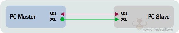
i2c wiring one master one slave
Because I2C uses addressing, multiple slaves can be controlled by a single master. With a 7-bit address, 128 (27) unique addresses are available. Using 10-bit addresses is uncommon but provides 1,024 (210) unique addresses. Up to 27 slave devices can be connected/addressed in the I2C interface circuit.
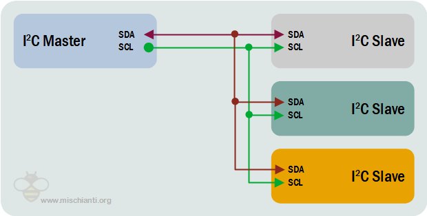
i2c wiring one master multiple slave
Multiple masters can be connected to a single slave or multiple slaves. The problem with multiple masters in the same system comes when two masters try to send or receive data at the same time over the SDA line. To solve this problem, each master needs to detect if the SDA line is low or high before transmitting a message. If the SDA line is low, this means that another master has control of the bus, and the master should wait to send the message. If the SDA line is high, then it’s safe to transmit the message. To connect multiple masters to multiple slaves
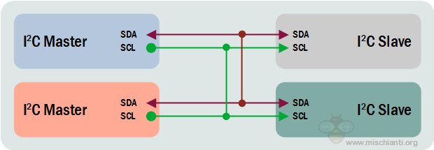
i2c wiring multiple master multiple slave
How to on Arduino SAMD MKR
Here new Arduino board on Amazon Arduino MKR WiFi 1010
SAMD21 can manage multiple (and configurable) serial interfaces with SERCOM (Serial Communication), which is a multiplexed serial configuration. It allows you to select various serial functions for most of your pins. For example, the ATmega328 has UART (RX/TX) on one pair of pins, I2C (SDA/SCL) on another set, and SPI (MOSI, MISO, SCK) on another set. The SAMD21 has 5 different internal ports which you can configure to use any combination of UART, I2C, and SPI.
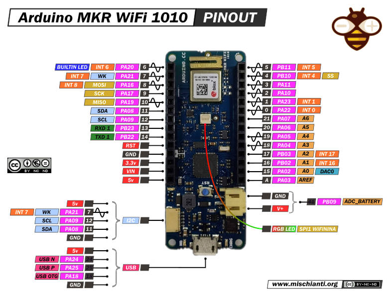
Arduino MKR WiFi 1010 pinouts low resolution
Arduino SAMD microcontrollers have six internal serial modules that can be configured individually, and just four of them are already configured. The other two are available for mapping onto specific pins.
| SERCOM | Protocol | Pins |
|---|---|---|
| SERCOM 0 | I2C | SDA: PIN 11SCL: PIN 12 |
| SERCOM 1 | SPI | MOSI: PIN 8SCK: PIN 9MISO: PIN 10 |
| SERCOM 5 | UART | RX: PIN 13TX: PIN 14 |
Internally usually, SERCOM 2 is used to manage additional interfaces like WiFi, Ethernet, or RGB LED.
| SERCOM | Protocol | Pins |
|---|---|---|
| SERCOM 2 | SPI | MOSI: PIN 26SCK: PIN 27MISO: PIN 29 |
Here a simple code that read from Wire and print to Serial.
#include <Wire.h>
void setup() { Wire.begin(); // join i2c bus (address optional for master) Serial.begin(9600); // start serial for output }
void loop() { Wire.requestFrom(8, 6); // request 6 bytes from slave device #8
while (Wire.available()) { // slave may send less than requested char c = Wire.read(); // receive a byte as character Serial.print(c); // print the character } }
You can specify the address as a parameter at the begin.
Arduino SAMD integrated I2C devices
If you connect an Arduino SAMD as Slave and another microcontroller as Master and launch an I2C scanner from Master like this:
I2C address scanner
#include <Wire.h>
void setup() { Wire.begin();
Serial.begin(9600); Serial.println("\nI2C Scanner"); }
void loop() { byte error, address; int nDevices;
Serial.println("Scanning...");
nDevices = 0; for(address = 1; address < 127; address++ ) { // The i2c_scanner uses the return value of // the Write.endTransmisstion to see if // a device did acknowledge to the address. Wire.beginTransmission(address); error = Wire.endTransmission();
if (error == 0)
{
  Serial.print("I2C device found at address 0x");
  if (address<16)
    Serial.print("0");
  Serial.print(address,HEX);
  Serial.println("  !");

  nDevices++;
}
else if (error==4)
{
  Serial.print("Unknow error at address 0x");
  if (address<16)
    Serial.print("0");
  Serial.println(address,HEX);
}
} if (nDevices == 0) Serial.println("No I2C devices found\n"); else Serial.println("done\n");
delay(5000); // wait 5 seconds for next scan }
you get this Serial output.
Scanning... I2C device found at address 0x60 ! I2C device found at address 0x6B ! done
This happens because devices like my Arduino MKR1010 WiFi uses I2C to control some integrated IC.
In this case, you have:
- Address 0x60: ATECC508 crypto chip;
- Address 0x6B: BQ24195L Linear Battery Charger.
These devices share the same I2C SERCOM, and have a specified library.
ATECC508 crypto chip
This chip It’s the most important element for IoT management. With this chip you can create certificate, store key and manage complex authentication pattern.
Here the specs:
- Cryptographic Co-processor with Secure Hardware-Based Key Storage
- Performs High-Speed Public Key (PKI) Algorithms
- ECDSA: FIPS186-3 Elliptic Curve Digital Signature Algorithm
- ECDH: FIPS SP800-56A Elliptic Curve Diffie-Hellman Algorithm
- NIST Standard P256 Elliptic Curve Support
- SHA-256 Hash Algorithm with HMAC Option
- Host and Client Operations
- 256-bit Key Length
- Storage for up to 16 Keys
- Two High-Endurance Monotonic Counters
- Guaranteed Unique 72-bit Serial Number
- Internal High-Quality FIPS Random Number Generator (RNG)
- 10 Kb EEPROM Memory for Keys, Certificates, and Data
- Multiple Options for Consumption Logging and One-Time Write Information
- Intrusion Latch for External Tamper Switch or Power-on Chip Enablement. Multiple I/O Options:
- High-speed Single Pin Interface, with One GPIO Pin
- 1 MHz Standard I2C Interface • 2.0V to 5.5V Supply Voltage Range
But you don’t manage It directly via the Wire library; Arduino offers you a specific library named ArduinoECCX08 to perform a lot of operations; some are very basic, and others are quite complex.
In this tutorial, we aren’t going to see It in deep, and we are going to use very basic features of this IC.
Random number generator with ATECC508A.
Here is a simple sketch that uses this chip to generate a random number.
#include <ArduinoECCX08.h>
void setup() { Serial.begin(9600); while (!Serial);
if (!ECCX08.begin()) { Serial.println("Failed to communicate with ECC508/ECC608!"); while (1); }
if (!ECCX08.locked()) { Serial.println("The ECC508/ECC608 is not locked!"); while (1); } }
void loop() { Serial.print("Random number = "); Serial.println(ECCX08.random(65535));
delay(1000); }
The result on Serial output is:
Random number = 60064 Random number = 25721 Random number = 22114 Random number = 29821 Random number = 57728 Random number = 43901 Random number = 39609 Random number = 45488 Random number = 28179
BQ24195L Linear Battery Charger
The BQ24195L It the IC that is used to the Arduino battery powered version like my MKR1010. You can ask to It the battery level, but you can check It from an ADC pin like in this sketch:
/*
This code is based on the readAnalogVoltage tutorial. For a deeper explanation about the code in this tutorial please refer to it.
ReadBatteryVoltage Reads the analog input connected to the battery output on a MKRZero or MKR1000, converts it to voltage, and prints the result to the serial monitor. Graphical representation is available using serial plotter (Tools > Serial Plotter menu)
This example code is in the public domain. */
// the setup routine runs once when you press reset: void setup() { // initialize serial communication at 9600 bits per second: Serial.begin(9600); }
// the loop routine runs over and over again forever: void loop() { // read the input on analog pin 0: int sensorValue = analogRead(ADC_BATTERY); // Convert the analog reading (which goes from 0 - 1023) to a voltage (0 - 4.3V): float voltage = sensorValue * (4.3 / 1023.0); // print out the value you read: Serial.print(voltage); Serial.println("V"); }
but with the specified library Arduino_BQ24195 you can configure the max voltage, min voltage, max ampere the overload voltage limit or enable/disable the charge mode. Here is the default sketch example.
/* Battery Charge Example This example shows how to configure and enable charge mode on Arduino MKR boards Circuit:
- Arduino MKR board
- 750 mAh LiPo battery
This sample code is part of the public domain. */
#include <Arduino_PMIC.h>
void setup() { Serial.begin(9600); while (!Serial) { ; // wait for serial port to connect. Needed for native USB port only }
if (!PMIC.begin()) { Serial.println("Failed to initialize PMIC!"); while (1); }
// Set the input current limit to 2 A and the overload input voltage to 3.88 V if (!PMIC.setInputCurrentLimit(2.0)) { Serial.println("Error in set input current limit"); }
if (!PMIC.setInputVoltageLimit(3.88)) { Serial.println("Error in set input voltage limit"); }
// set the minimum voltage used to feeding the module embed on Board if (!PMIC.setMinimumSystemVoltage(3.5)) { Serial.println("Error in set minimum system volage"); }
// Set the desired charge voltage to 4.2 V if (!PMIC.setChargeVoltage(4.2)) { Serial.println("Error in set charge volage"); }
// Set the charge current to 375 mA // the charge current should be defined as maximum at (C for hour)/2h // to avoid battery explosion (for example for a 750 mAh battery set to 0.375 A) if (!PMIC.setChargeCurrent(0.375)) { Serial.println("Error in set charge current"); } Serial.println("Initialization done!"); }
void loop() { // Enable the Charger if (!PMIC.enableCharge()) { Serial.println("Error enabling Charge mode"); } // canRunOnBattery() returns true if the battery voltage is < the minimum // systems voltage if (PMIC.canRunOnBattery()) { // loop until charge is done while (PMIC.chargeStatus() != CHARGE_TERMINATION_DONE) { delay(1000); } // Disable the charger and loop forever Serial.println("Disable Charge mode"); if (!PMIC.disableCharge()) { Serial.println("Error disabling Charge mode"); } while (1); // if you really want to detach the battery call // PMIC.disableBATFET(); //isbatteryconnected = false; } delay(100); }
Here is the Serial output.
Initialization done! Disable Charge mode
Network

Arduino SAMD MKR UNO MEGA connected via i2c, master multiple slave
Like Arduino standard, Arduino SAMD MKR has the possibility to self assign an I2C address so we can create a network.
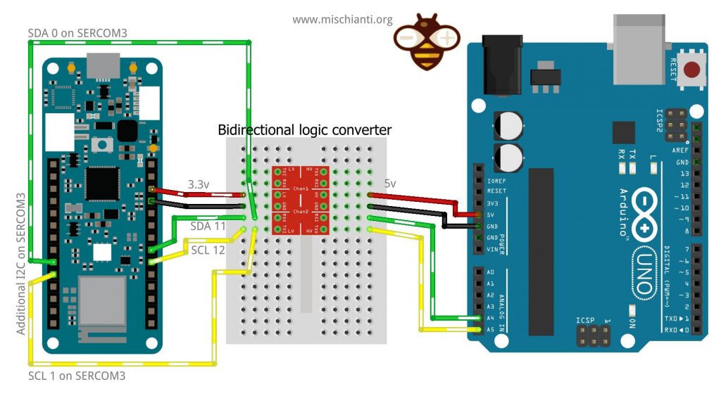
For the connection with the same logic and voltage, refer “i2c Arduino: how to create network, parameters and address scanner“, here I am going to connect via I2C an Arduino MKR1010 WiFi with an Arduino UNO.
You must remember that Arduino UNO has 5v logic, Arduino MKR has 3.3v logic, and It isn’t 5v tolerant.
Here the bidirectional logic converter Aliexpress
And here the classic series of Arduino board Arduino UNO - Arduino MEGA 2560 R3 - Arduino Nano - Arduino Pro Mini
One master one slave
The connection is simple 3.3v of Arduino MKR must connect to LV, and to the side of Low Voltage, you must connect the SDA 11 to an LV1 and SCL 12 to LV2, the 5v of Arduino UNO to HV and SDA A4 to HV1 and SCL A5 to HV2.

i2c Arduino MKR SAMD and Arduino UNO network wiring
The code for the master is the same as explained in the previous article and works with both microcontrollers.
/**
- i2c network: send parameter to client and receive response
- with data relative to the request. MASTER SKETCH
- by Renzo Mischianti <www.mischianti.org>
- https://mischianti.org
- Arduino UNO <------> Logic converter <------> Arduino MKR
- GND GND GND GND
- 5v HV LV 3.3v
- A4 HV1 LV1 11
- A5 HV2 LV2 12
- */
#include <Wire.h>
enum REQUEST_TYPE { NONE = -1, GET_NAME = 0, GET_AGE };
void setup() { Wire.begin(); // join i2c bus (address optional for master) Serial.begin(9600); // start serial for output
while (!Serial){}

Wire.beginTransmission(0x10); 	// Start channel with slave 0x10
Wire.write(GET_NAME);        		// send data to the slave
Wire.endTransmission();       	// End transmission

// Now the request

Wire.requestFrom(0x10, 14);    // request 14 bytes from slave device 0x10

while (Wire.available()) { // slave may send less than requested
    char c = Wire.read(); // receive a byte as character
    Serial.print(c);         // print the character
}

Serial.println();

delay(1000); // added to get better Serial print

Wire.beginTransmission(0x10); 	// Start channel with slave 0x10
Wire.write(GET_AGE);        		// send data to the slave
Wire.endTransmission();       	// End transmission

// Now the request

Wire.requestFrom(0x10, 1);    // request 1 bytes from slave device 0x10

while (Wire.available()) { // slave may send less than requested
    int c = (int)Wire.read(); // receive a byte as character
    Serial.println(c);         // print the character
}
}
void loop() { }
To understand the basic commands of I2C refer to the “I2C Arduino article”.
The slave sketch also is the same, I change only the address to 0x10.
/**
- i2c network: send parameter to client and receive response
- with data relative to the request. SLAVE SKETCH 3
- by Renzo Mischianti <www.mischianti.org>
- https://mischianti.org
- Arduino UNO <------> Logic converter <------> Arduino MKR
- GND GND GND GND
- 5v HV LV 3.3v
- A4 HV1 LV1 11
- A5 HV2 LV2 12
- */
#include <Wire.h>
enum I2C_REQUEST_TYPE { NONE = -1, GET_NAME = 0, GET_AGE };
void requestEvent(); void receiveEvent(int numBytes);
I2C_REQUEST_TYPE request = NONE;
void setup() { Wire.begin(0x10); // join i2c bus with address 0x10
Serial.begin(9600);  // start serial for output

while (!Serial){}

// event handler initializations
Wire.onReceive(receiveEvent);    // register an event handler for received data
Wire.onRequest(requestEvent);   // register an event handler for data requests
}
void loop() { // delay(100); }
// function that executes whenever data is requested by master // this function is registered as an event, see setup() void requestEvent() { switch (request) { case NONE: Serial.println(F("Not good, no request type!")); break; case GET_NAME: Wire.write("ArduinoMKR "); // send 14 bytes to master request = NONE; break; case GET_AGE: Wire.write((byte)47); // send 1 bytes to master request = NONE; break; default: break; } }
// function that executes whenever data is received by master // this function is registered as an event, see setup() void receiveEvent(int numBytes) { if (numBytes==1){ int requestVal = Wire.read();
    Serial.print(F("Received request -> "));
    Serial.println(requestVal);
    request = static_cast<I2C_REQUEST_TYPE>(requestVal);
}else{
    Serial.print(F("No parameter received!"));
}
}
One master and multiple slave with parameter transfer
Now we are going to extend the “One master multiple slave” example, adding the Arduino MKR1010 WiFi like so.

i2c Arduino MKR SAMD multi slave with UNO MEGA network wiring
Now the Master sketch with the request to our MKR.
/**
- i2c network: send parameter to client and receive response
- with data relative to the request
- by Renzo Mischianti <www.mischianti.org>
- https://mischianti.org
- Arduino UNO <------> Logic converter <------> Arduino MKR
- GND GND GND GND
- 5v HV LV 3.3v
- A4 HV1 LV1 11
- A5 HV2 LV2 12
- */
#include <Wire.h>
enum REQUEST_TYPE { NONE = -1, GET_NAME = 0, GET_AGE };
void setup() { Wire.begin(); // join i2c bus (address optional for master) Serial.begin(9600); // start serial for output
while (!Serial){}
Serial.flush();
Serial.println();

Wire.beginTransmission(0x08); 	// Start channel with slave 0x08
Wire.write(GET_NAME);        		// send data to the slave
Wire.endTransmission();       	// End transmission

delay(1000); // added to get better Serial print

Wire.requestFrom(0x08, 14);    // request 14 bytes from slave device 0x08

while (Wire.available()) { // slave may send less than requested
    char c = Wire.read(); // receive a byte as character
    Serial.print(c);         // print the character
}

Serial.println();

Wire.beginTransmission(0x09); 	// Start channel with slave 0x09
Wire.write(GET_NAME);        		// send data to the slave
Wire.endTransmission();       	// End transmission

delay(1000); // added to get better Serial print

Wire.requestFrom(0x09, 14);    // request 14 bytes from slave device 0x09

while (Wire.available()) { // slave may send less than requested
    char c = Wire.read(); // receive a byte as character
    Serial.print(c);         // print the character
}

Serial.println();

Wire.beginTransmission(0x10); 	// Start channel with slave 0x10
Wire.write(GET_NAME);        		// send data to the slave
Wire.endTransmission();       	// End transmission

delay(1000); // added to get better Serial print

Wire.requestFrom(0x10, 14);    // request 14 bytes from slave device 0x10

while (Wire.available()) { // slave may send less than requested
    char c = Wire.read(); // receive a byte as character
    Serial.print(c);         // print the character
}

Serial.println();

delay(1000); // added to get better Serial print

Wire.beginTransmission(0x08); 	// Start channel with slave 0x08
Wire.write(GET_AGE);        		// send data to the slave
Wire.endTransmission();       	// End transmission

delay(1000); // added to get better Serial print

Wire.requestFrom(0x08, 1);    // request 1 bytes from slave device 0x08

while (Wire.available()) { // slave may send less than requested
    int c = (int)Wire.read(); // receive a byte as character
    Serial.println(c);         // print the character
}

Wire.beginTransmission(0x09); 	// Start channel with slave 0x09
Wire.write(GET_AGE);        		// send data to the slave
Wire.endTransmission();       	// End transmission

delay(1000); // added to get better Serial print

Wire.requestFrom(0x09, 1);    // request 1 bytes from slave device 0x09

while (Wire.available()) { // slave may send less than requested
    int c = (int)Wire.read(); // receive a byte as character
    Serial.println(c);         // print the character
}

Wire.beginTransmission(0x10); 	// Start channel with slave 0x10
Wire.write(GET_AGE);        		// send data to the slave
Wire.endTransmission();       	// End transmission

delay(1000); // added to get better Serial print

Wire.requestFrom(0x10, 1);    // request 1 bytes from slave device 0x10

while (Wire.available()) { // slave may send less than requested
    int c = (int)Wire.read(); // receive a byte as character
    Serial.println(c);         // print the character
}
}
void loop() { }
The master result now is
ArduinoUNO
ArduinoMEGA
ArduinoMKR
43
45
47
Add new I2C interface with SERCOM

Arduino SAMD MKR UNO connected via i2c master with multiple slaves on the same device
As described SAMD devices have a set of SERCOM interfaces that can be configured as UART, SPI, or I2C.
Check the previous schema and select a free SERCOM interface; I select SERCOM3 for my purpose.
I’m going to use pin 0 as SDA and pin 1 as SCL, to assign this I2C interface to SERCOM3 you must first instantiate the Wire interface.
TwoWire myWire(&sercom3, 0, 1); // Create the new wire instance assigning it to pin 0 and 1
Then you must specify that PIN 0 and PIN 1 are SERCOM pins.
myWire.begin(0x11);                // join i2c bus on sercom3 with address 0x11
pinPeripheral(0, PIO_SERCOM);   //Assign SDA function to pin 0
pinPeripheral(1, PIO_SERCOM);   //Assign SCL function to pin 1
Now the most important thing is to attach the interrupt handler to the SERCOM.
// Attach the interrupt handler to the SERCOM extern "C" {
void SERCOM3_Handler(void);
void SERCOM3_Handler(void) {
myWire.onService();} }
Now your new I2C interface is ready and can be used as SLAVE like the other, and I assigned to this new interface address 0x11.
myWire.begin(0x11); // join i2c bus on sercom3 with address 0x11And I add I add 2 new receive and request event callbacks.
// event handler initializations
myWire.onReceive(receiveEventSercom);    // register an event handler for received data
myWire.onRequest(requestEventSercom);   // register an event handler for data requests
Now you must wire this new I2C interface.
i2c Arduino MKR SAMD and Arduino UNO network with additional i2c on SERCOM
If you launch a new I2C address scanner, the result on the master Serial is this.
Scanning... I2C device found at address 0x10 ! I2C device found at address 0x11 ! I2C device found at address 0x60 ! I2C device found at address 0x6B ! done
You can find new I2C devices that correspond to our SERCOM3 I2C.
Here is the complete double SLAVE sketch for Arduino MKR 1010 WiFi.
/**
- i2c network: send parameter to client and receive response
- with data relative to the request. SLAVE SKETCH 4
- We are going to create 2 i2c SLAVE on 2 different SERCOM
- interface, the first with address 0x10 to the standard Wire
- the second on additional i2c SERCOM3 interface
- by Renzo Mischianti <www.mischianti.org>
- https://mischianti.org
- Arduino UNO <------> Logic converter <------> Arduino MKR <------> Arduino MKR
- GND GND GND GND
- 5v HV LV 3.3v
- A4 HV1 LV1 11 1
- A5 HV2 LV2 12 0
- */
#include <Wire.h> #include "wiring_private.h"
TwoWire myWire(&sercom3, 0, 1); // Create the new wire instance assigning it to pin 0 and 1
enum I2C_REQUEST_TYPE { NONE = -1, GET_NAME = 0, GET_AGE }; void requestEvent(); void receiveEvent(int numBytes); void requestEventSercom(); void receiveEventSercom(int numBytes);
I2C_REQUEST_TYPE request = NONE; I2C_REQUEST_TYPE request_sercom = NONE;
void setup() { Wire.begin(0x10); // join i2c bus with address 0x10
myWire.begin(0x11);                // join i2c bus on sercom3 with address 0x11
pinPeripheral(0, PIO_SERCOM);   //Assign SDA function to pin 0
pinPeripheral(1, PIO_SERCOM);   //Assign SCL function to pin 1

Serial.begin(9600);  // start serial for output

while (!Serial){}

// event handler initializations
Wire.onReceive(receiveEvent);    // register an event handler for received data
Wire.onRequest(requestEvent);   // register an event handler for data requests
// event handler initializations
myWire.onReceive(receiveEventSercom);    // register an event handler for received data
myWire.onRequest(requestEventSercom);   // register an event handler for data requests
}
void loop() { delay(100); }
// function that executes whenever data is requested by master // this function is registered as an event, see setup() void requestEvent() { switch (request) { case NONE: Serial.println(F("Not good, no request type!")); break; case GET_NAME: Wire.write("ArduinoMKR "); // send 14 bytes to master request = NONE; break; case GET_AGE: Wire.write((byte)47); // send 1 bytes to master request = NONE; break; default: break; } }
// function that executes whenever data is received by master // this function is registered as an event, see setup() void receiveEvent(int numBytes) { if (numBytes==1){ int requestVal = Wire.read();
    Serial.print(F("Received request -> "));
    Serial.println(requestVal);
    request = static_cast<I2C_REQUEST_TYPE>(requestVal);
}else{
    Serial.print(F("No parameter received!"));
}
}
// function that executes whenever data is requested by master // this function is registered as an event, see setup() void requestEventSercom() { switch (request_sercom) { case NONE: Serial.println(F("Not good, no request type!")); break; case GET_NAME: myWire.write("ArduinoMKR SER"); // send 14 bytes to master request_sercom = NONE; break; case GET_AGE: myWire.write((byte)57); // send 1 bytes to master request_sercom = NONE; break; default: break; } }
// function that executes whenever data is received by master // this function is registered as an event, see setup() void receiveEventSercom(int numBytes) { if (numBytes==1){ int requestVal = myWire.read();
    Serial.print(F("Received request on SERCOM3 -> "));
    Serial.println(requestVal);
    request_sercom = static_cast<I2C_REQUEST_TYPE>(requestVal);
}else{
    Serial.print(F("No parameter received!"));
}
}
// Attach the interrupt handler to the SERCOM extern "C" {
void SERCOM3_Handler(void);
void SERCOM3_Handler(void) {
myWire.onService();} }
Now, if we are going to change the master sketch to ask for information to this new interface also, here the master sketch for this purpose.
/**
- i2c network: send parameter to client and receive response
- with data relative to the request
- by Renzo Mischianti <www.mischianti.org>
- https://mischianti.org
- Arduino UNO <------> Arduino UNO
- GND GND
- A4 A4
- A5 A5
- */
#include <Wire.h>
enum REQUEST_TYPE { NONE = -1, GET_NAME = 0, GET_AGE };
void setup() { Wire.begin(); // join i2c bus (address optional for master) Serial.begin(9600); // start serial for output
while (!Serial){}
Serial.flush();
Serial.println();

Wire.beginTransmission(0x10); 	// Start channel with slave 0x10
Wire.write(GET_NAME);        		// send data to the slave
Wire.endTransmission();       	// End transmission

delay(1000); // added to get better Serial print

Wire.requestFrom(0x10, 14);    // request 14 bytes from slave device 0x10

while (Wire.available()) { // slave may send less than requested
    char c = Wire.read(); // receive a byte as character
    Serial.print(c);         // print the character
}

Serial.println();

Wire.beginTransmission(0x11); 	// Start channel with slave 0x11
Wire.write(GET_NAME);        		// send data to the slave
Wire.endTransmission();       	// End transmission

delay(1000); // added to get better Serial print

Wire.requestFrom(0x11, 14);    // request 14 bytes from slave device 0x11

while (Wire.available()) { // slave may send less than requested
    char c = Wire.read(); // receive a byte as character
    Serial.print(c);         // print the character
}

Serial.println();

delay(1000); // added to get better Serial print

Wire.beginTransmission(0x10); 	// Start channel with slave 0x10
Wire.write(GET_AGE);        		// send data to the slave
Wire.endTransmission();       	// End transmission

delay(1000); // added to get better Serial print

Wire.requestFrom(0x10, 1);    // request 1 bytes from slave device 0x10

while (Wire.available()) { // slave may send less than requested
    int c = (int)Wire.read(); // receive a byte as character
    Serial.println(c);         // print the character
}

Wire.beginTransmission(0x11); 	// Start channel with slave 0x11
Wire.write(GET_AGE);        		// send data to the slave
Wire.endTransmission();       	// End transmission

delay(1000); // added to get better Serial print

Wire.requestFrom(0x11, 1);    // request 1 bytes from slave device 0x11

while (Wire.available()) { // slave may send less than requested
    int c = (int)Wire.read(); // receive a byte as character
    Serial.println(c);         // print the character
}
}
void loop() { }
And here is the Serial output of the master sketch:
ArduinoMKR
ArduinoMKR SER
47
57
As you can see, the 2 i2c interfaces are independent channels, and the same microcontroller results in multiple I2C slaves.
Thanks
- Arduino SAMD NINA: pinout, specs and Arduino IDE configuration
- Arduino SAMD NINA: WiFiNINA, firmware update, and RGB led
- Arduino SAMD (NANO 33 and MKR): SPI flash memory FAT FS
- i2c Arduino SAMD MKR: additional interface SERCOM, network and address scanner
- Arduino MKR SAMD: FAT filesystem on external SPI flash memory
- Connecting the EByte E70 to Arduino SAMD (Nano 33, MKR…) devices and a simple sketch example
- i2c Arduino: how to create a network, parameters, and address scanner
- i2c Arduino SAMD MKR: additional interface SERCOM, network, and address scanner
- i2c esp8266: how to, network 5v, 3.3v, speed, and address scanner
- Guide to I2C on ESP32: Communication with Heterogeneous 5V and 3.3V Devices, Additional Interface Management and Scanner