Simultaneous imaging of different focal planes in fluorescence microscopy for the study of cellular dynamics in three dimensions (original) (raw)
. Author manuscript; available in PMC: 2009 Oct 14.
Published in final edited form as: IEEE Trans Nanobioscience. 2004 Dec;3(4):237–242. doi: 10.1109/tnb.2004.837899
Abstract
The imaging of cellular dynamics in three dimensions using a standard microscope is severely limited due to the fact that only one focal plane can be imaged at a given point in time. Here we present a modification of the classical microscope design with which two or more focal planes can be imaged simultaneously. This is achieved by a modification of the emission pathway of a standard microscope. The efficacy of the design is shown by imaging bead samples and a FcRn-GFP transfected tubule that leaves a sorting endosome and subsequently exocytoses at the plasma membrane.
Index Terms: Fluorescence microscopy, three dimensional tracking, trafficking pathway, biological cells
I. Introduction
Fluorescence microscopy of live cells is an important tool to investigate cellular trafficking pathways. Much improved fluorescent labeling techniques, not least the use of the green fluorescent protein (GFP), in combination with highly sensitive detectors allows for new types of experiments to be carried out that have led to significant advances in the understanding of cellular events [1]. The current microscope design is very well suited to image fast moving organelles in one focal plane. In addition, the sensitivity of CCD detectors allows for the use of relatively high frame rates. However, the imaging of organelles as they move between different focal planes poses a significant problem. This is due to the fact that as the organelle leaves the current focal plane the focal plane has to be changed. This can be done by the use of a focusing device such as a piezo z-focus. However, such focusing devices are relatively slow, typically taking tens of milli seconds to move the focal plane even by a fairly short distance. In addition, independent of the speed of the z-focus, only one focal plane can be imaged at a time. As a result, important events may not be imaged if they are not in focus.
These limitations make it very difficult to image relatively rapid, intracellular trafficking processes that are of central interest to cell biologists. For example, due to the rapid movement of the organelles involved and the distance between the locations of the sorting endosomes and the plasma membrane, the tracking of tubules or vesicles on the recycling pathway leading from sorting endosomes to exocytosis has, in general, not been possible.
A central problem with current microscope setups is that only one focal plane can be imaged at a time and that imaging of different focal planes is therefore limited by the time taken to readjust the focus to a distinct plane. Here we address this problem by proposing a novel microscope design with which two or more focal planes can be imaged simultaneously. This is achieved by a modification of the emission pathway of a standard fluorescence microscope and by using a dual camera acquisition format with which two different focal planes can be imaged at the same time.
Our proposed design requires a reconfiguration of a standard fluorescence microscope. This reconfiguration is, however, such that existing setups could be altered to incorporate the proposed approach without necessitating major modifications. We expect that this novel design will become an important tool in the study of intracellular trafficking pathways in live cells.
II. Materials and Methods
Sample preparation
Preparation of Bead Samples
Fluoresbrite carboyxlate YG 1 _μ_m or fluoresbrite carboxylate YG 100 nm diameter beads (both from Polysciences Inc, Warrington) were resuspended at 4.5 × 10⁷ or 4.55 × 10⁸ beads/ml, respectively, in MilliQ water. 150 _μ_l of the bead suspension was added to coverslips and allowed to air dry for 24 hours. Prior to imaging, 1 ml of MilliQ water was added to the dish.
Plasmid constructs
Expression constructs encoding the chain of FcRn linked to enhanced GFP (eGFP) in pEGFP-N1 (Clontech) and human _β_2-microglobulin in pCB7 have been described previously ([2]). An analogous plasmid with the same polylinker and reading frame as pEGFP-N1 was generated by replacement of the EGFP gene in pEGFP-N1 by the monomeric red fluorescent protein gene (mRFP [3]); generously provided by Dr. R. Tsien, University of California at San Diego using standard methods. The FcRn _α_-chain gene was recloned into this mRFP plasmid (‘mRFP-N1’) as an EcoRI fragment.
Maintenance and transfection of HMEC-1 cells
HMEC-1 cells ([4]) were maintained and transfected as described previously ([2]). Cells were cotransfected with constructs encoding the FcRn _α_-chain gene in pEGFP-N1, mRFP-N1 and human _β_2-microglobulin.
Dual focal plane microscope
A Zeiss Axiovert S100 was modified by removing the standard optical emission system and replacing it by a custom built emission system (see Fig. 1 for a sketch of the layout). In the emission light path of the objective a beam splitter is inserted to split the emitted light into two paths. In each of the two paths an appropriate emission filter is inserted followed by a tube lens that focuses the image onto the detector. The important feature of this design is that one of the cameras (Camera 2 in Fig. 1) is positioned on a translation stage that allows the distance to be changed between this camera and the tube lens. Changing this distance results in introducing a difference in the focal planes that are imaged by the two cameras.
Fig. 1.
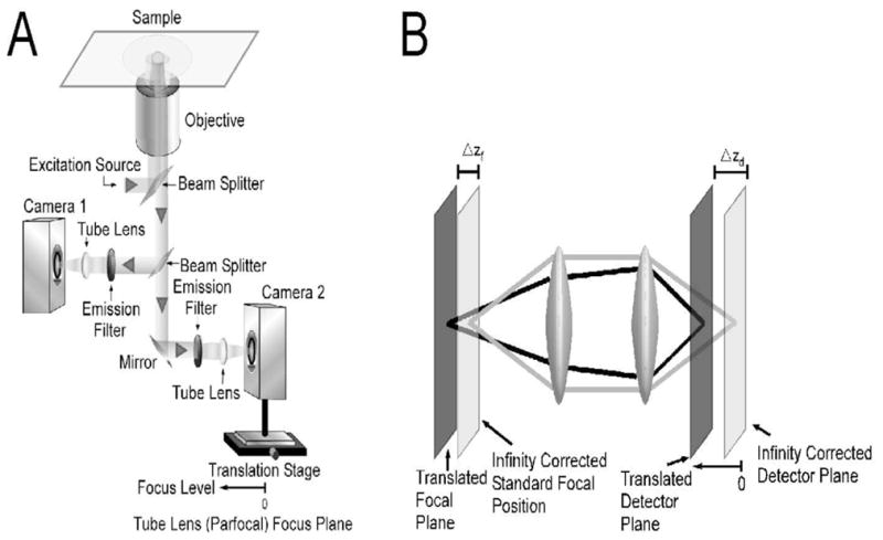
(A) Layout of microscope configuration. The emission path is split by a beam splitter into two paths. In each of those two paths emission filters are followed by a tube lens that focuses the image onto the detector. One focusing method is provided by the focusing mechanism of the microscope (not shown) by changing the position of the objective with respect to the sample. The focal plane that is imaged with camera 1 is adjusted in this way. The focal plane that is imaged by camera 2 is additionally adjustable through the position of the translation stage on which camera 2 is mounted. This translation stage changes the distance of the detector of camera 2 with respect to the tube lens. In contrast, the detector of camera 1 is located at the focal plane of its tube lens. If the detector of camera 2 is also put at the focal plane of the tube lens both cameras will image the same focal plane in the sample. Changing the position of camera 2 away from the focal plane of the tube lens changes the focal plane in the sample that is imaged by camera 2. Moving camera 2 towards the tube lens results in imaging planes in the sample that are further away from the cover glass.
(B) Sketch of emission light path that shows how a detector position different from the typical infinity corrected position results in the imaging of a focal plane that is further from the cover glass than the focal plane corresponding to the standard configuration.
All images were acquired using a 100x Zeiss NA1.45 objective that is suitable for total internal reflection excitation. Using a custom beam steering setup two laser lines were used for excitation: 488 nm laser (Laser Physics, West Jordan, UT), 543 nm laser (Research Electro-Optics, Boulder, CO). Custom filter sets and beam splitters were used (Chroma Technology Corp, Brattleboro, VT) for combining the laser lines on a breadboard and guiding the emitted fluorescence to the camera. The bead samples were imaged with the 488nm laser in widefield mode. For the analysis of the cell sample the 488 nm laser line was focused onto the sample in total internal reflection mode ([5]) whereas the 543 nm line was used for widefield excitation. Images were acquired with two Orca ER cameras (Hamamatsu, Bridgewater, NJ) at a rate of 5 frames per second.
All data were processed in our Matlab (The Math-works, Inc., Natick, MA) based custom written software package Microscope Image Analysis Toolbox (MIATool) (see www4.utsouthwestern.edu/wardlab/miatool/). The images from the two cameras were registered with an approach that is based on a piecewise linear registration algorithm. Exocytosis is detected by inspection of the time lapse images and by plotting the fluorescence intensity over time for a region of interest A that contains the exocytic site and for a region of interest B that forms an annulus around the first region. An exocytic event is characterized by a dispersion of the fluorescence in the plasma membrane. Therefore the signal from region A will increase with the tubule coming in focus at the plasma membrane. This is followed by a rapid decrease of the signal in region A and a rapid increase in region B as the fluorescent molecules disperse into the plasma membrane.
Calibration
An important aspect of the novel dual focal plane setup is the calibration of the distances between the two focal planes. To do this and to demonstrate the functioning of the approach bead samples were prepared as above.
In our configuration (Fig. 1A) the position of Camera 1 is fixed whereas that of Camera 2 can be changed towards the tube lens. This position of Camera 2 was changed in increments of mm. For each position of Camera 2 a z-stack was acquired of the bead sample at 25 nm increments using a piezo z-focus system (Polytec-PI). For each z-focus position and each camera the fluorescence intensity of the images acquired for a 1 _μ_m bead are recorded and plotted (Fig. 2B). The distance between the maxima for the fluorescence intensity for each camera then gives a measurement for the distance of the focal planes at this position of Camera 2. Those distances are then plotted (appropriately calibrated to account for parfocality) and a least-squares fit to these data points reveals the relationship between the position of Camera 2 and the distance of the focal planes between the two cameras.
Fig. 2.
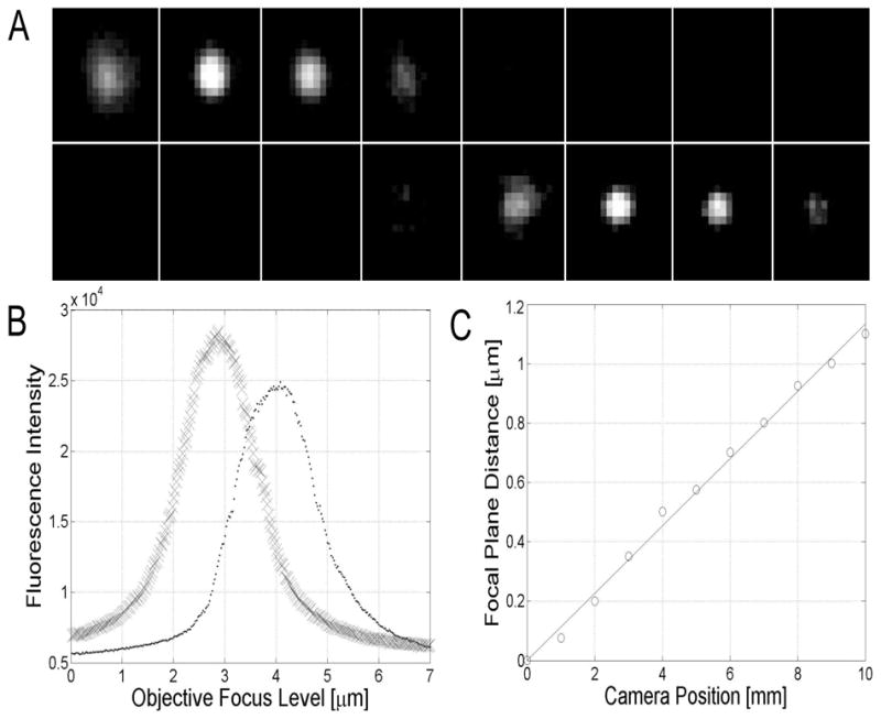
(A) Montage of images taken of a 100 nm diameter fluorescent bead with the two camera system for the imaging of different focal planes (Fig. 1). Camera 1 was positioned at the focal plane of the tube lens, whereas Camera 2 was positioned 8.8 mm away from the focal position towards the tube lens corresponding to a 1 _μ_m distance between the two focal planes (based on calibration data obtained from Fig. 2C). The top row shows images acquired by Camera 2 whereas the bottom row shows images acquired by Camera 1. The images were taken at different positions of the z-focus of the objective (from left to right the z-focus positions of the objective were: 1.125 _μ_m, 1.375 _μ_m, 1.625 _μ_m, 1.875 _μ_m, 2.125 _μ_m, 2.375 _μ_m, 2.625 _μ_m, 2.875 _μ_m). It is clearly seen that the bead is in focus at different planes for the two cameras, thereby confirming that the acquisition system allows the imaging of different focal planes. (B) Fluorescent intensities of the images acquired as in (A) plotted against objective z-focus levels. Here images are analyzed that were acquired at 25nm increments. The fluorescence intensity plots have different peaks indicating that the focal planes for the two cameras are different. (C) Measurement of the distance between the peaks of the plots in (B) gives a measurement of the difference in the focal planes between Camera 1 and Camera 2. For different positions of Camera 2 analyses of the images were carried out as in (B) that result in estimates of the difference in focal planes between the two cameras. The current plot reveals a linear relationship between the position of Camera 2 (X [mm]) and the difference in focal planes between the two cameras (Y [μ_m]), given by Y = 0.113_X
III. Results and Discussion
In the current study we have developed a novel design of the emission pathway of a microscope for the purpose of imaging two different focal planes simultaneously. The specifics of the design (Fig. 1) are discussed in the Methods Section. That this modified microscope is indeed capable of imaging two different focal planes was first verified by imaging a small fluorescent bead. In Fig. 2A the results are shown of the imaging of a 100 nm fluorescent bead. The bead was imaged with Camera 1 positioned at the focal plane of the tube lens, i.e. positioned at the standard location in a conventional microscope. Camera 2 was positioned 8.8 mm towards the tube lens from the parfocal position. In a montage plot images are shown that are acquired in the two cameras as the z-focus of the objective is incremented. The bead is clearly seen to be in focus at different positions of the objective z-focus. This shows that the imaging system indeed produces images at different focal planes. In Fig. 2B fluorescence intensity levels are recorded for different focal levels of the objective z-focus for a 1 _μ_m bead. These plots also confirm that the two cameras image two different focal planes. The difference between the peak positions of the two plots allow the determination of the distance of the focal planes for the two cameras. This is further analyzed in Fig. 2C where for different positions of Camera 2 with respect to the tube lens, the difference in focal planes was determined between the two cameras. For the range of positions of Camera 2 that were investigated there is a linear relationship between the position of Camera 2 and the difference in focal planes between the two cameras.
We next used the new imaging set up to analyze the trafficking of the Fc receptor, FcRn, in transfected, human endothelial cells (HMEC-1). In earlier studies we have shown that this receptor is a recycling receptor that sorts bound IgG molecules in the sorting endosomes ([2]). Receptor bound IgG is subsequently exocytosed ([6]). However, in these earlier studies we were not able to track the movement of an individual tubule or vesicle from the sorting endosome to an exocytic site at the plasma membrane due the distance between the plasma membrane and the sorting endosomes which are typically located at least around 0.8 _μ_m above the plasma membrane. In Fig. 3 images are shown of the results of a live-cell experiment using HMEC-1 cells cotransfected with FcRn-GFP and FcRn-mRFP. A sorting endosome is imaged in one focal plane (see [2] for the identification of the sorting endosome). The plasma membrane is simultaneously imaged in the second focal plane that is 0.88 _μ_m from the first focal plane. A tubule first leaves the sorting endosome. The tubule then travels in this focal plane for a number of frames, leaves this focal plane and emerges in the focal plane corresponding to the plasma membrane. Subsequent images of the focal plane of the plasma membrane show that the tubule moves along the plasma membrane until it partially fuses with the plasma membrane.
Fig. 3.

Time lapse images acquired with dual plane configuration of endothelial (HMEC-1) cell cotransfected with both FcRn-GFP and FcRn-RFP. One focal plane was set to image (images are labeled ‘L’) the plasma membrane (in TIRFM with a GFP specific filter set); the second focal plane (images are labeled ‘U’) was set to image the sorting endosome level (0.88 _μ_m above in widefield with a RFP specific filter set). The two images in the top left hand corner show a larger part of the cell with the sorting endosome marked by the box in both the upper and lower planes. The frame in image 10 shows the excerpt that is presented for the subsequent images. Images are shown for both focal planes. The number in the bottom right hand corner indicates the time of acquisition (in seconds). The frames in the upper level show how a tubule leaves the sorting endosome (images 1U–6U). This tubule then breaks up (images 9U–10U). One of the two resulting tubules (arrow) then starts to leave the sorting endosome level and appears in the membrane level (image 14 onwards) until it has completely disappeared from the sorting endosome level (image 21U). After arriving on the membrane the tubule partially exocytoses (27L–30L). The fluorescence intensity plots confirm this partial fusion event. Size bars equal 2 _μ_m.
The presented technique has also been successfully applied to image cellular events away from the plasma membrane with two focal planes such as tubular behavior above and below a sorting endosome (data not shown). These events were imaged in widefield mode. Total internal reflection fluorescence microscopy (TIRFM) is a widely used technique to image dynamic cellular events near the plasma membrane ([7], [8], [9]). The reason for the success of TIRFM lies in the fact that out of focus fluorescence does not interfere since only a thin layer near the cover glass is illuminated ([5]). To take advantage of the properties of TIRFM, and also to clearly visualize exocytosis ([6]) the images for the plasma membrane in Fig. 3 were acquired in TIRFM mode. The plasma membrane was illuminated in TIRFM mode with the 488 nm laser to excite FcRn-GFP. The 543 nm laser was used in widefield illumination to excite FcRn-mRFP. Due to the spectral separation of GFP and mRFP, the mRFP emission does not obscure the events that are imaged in proximity to the plasma membrane. Thereby the advantages of TIRFM imaging can be preserved while at the same time the cell is illuminated in widefield mode to allow the imaging of the sorting endosomes.
The design of the emission light path described here allows for the simultaneous imaging of two focal planes. This approach can be generalized in a relatively straightforward manner so that additional focal planes can be imaged by inserting further beamsplitters into the emission light path and repeating the setup for Camera 2 using the current design. In this context it is important to point out that for the purposes of tracking, only relatively few focal planes need to be imaged that can be significant distances apart. This is in contrast to other approaches that aim to obtain a full reconstruction of the cell for which it is necessary to acquire images for focal planes that are much more closely spaced.
In [10], [11], [12], [13] methodologies were proposed that are suitable for the tracking of a labeled object such as a bead using a confocal microscope. Based on a measurement of the current position of the bead the z-focus of the microscope is adjusted in a feedback scheme to track the bead. However, for image based sensors and the tracking of organelles this approach appears less well suited than the approach presented here, since the objects that are to be tracked can typically only be identified in a post-acquisition examination of the acquired imaging data. Our design does not only allow the simultaneous imaging of focal planes that can be significantly apart. It also avoids the vibrational disturbances that can occur when the focal plane is changed using a standard focusing device. Our new approach can, of course, be combined with changes of the focal planes using a focusing drive should this be desirable. The current study was carried out for fluorescence microscopy. The underlying principles, however, also apply to other imaging approaches such as transmitted illumination.
In summary, we have described a new imaging modality with which cellular events can simultaneously be imaged at two or more focal planes. This approach, for example, circumvents earlier limitations for the tracking of entire intracellular trafficking pathways. In the example presented, we demonstrate that it is possible to use this method to follow the movement of the same tubule along the part of the recycling pathway that spans from the sorting endosome to exocytosis at the plasma membrane. Such an imaging method therefore has obvious implications for the study of this, and numerous other, intracellular trafficking pathways. Importantly, the proposed redesign of a microscope does not require a severe modification to existing microscope set ups, and could readily be incorporated into standard microscope bodies. We therefore expect that this imaging method will become an important and readily available tool for the study of cellular dynamics in three dimensions.
Acknowledgments
The authors would like to thank J. Zhou and C. Martinez for assistance in carrying out the experiments and P. Long for help in producing the sketches.
The research was supported in part by grants from the National Institutes of Health (NIH RO1 AI50747, R21 AI 53748, R01 AI 39167).
Biographies
 Prashant Prabhat was born in Bihar, India in 1976. He received the Bachelors Degree in Mechanical Engineering from Manipal Insitute of Technology, Karnataka, India in 1998, and the Masters Degree in Mechanical Engineering from University of Missouri, Rolla in 2003. He is currently a graduate student and a research assistant at the department of Electrical Engineering, University of Texas at Dallas and a fellow at the University of Texas Southwestern Medical Center at Dallas.
He worked at the automotive research and development division of Mahindra and Mahindra Ltd, India in 1998-1999. In his masters program he worked in the area of neural networks and control. His current research is related to Bioengineering and is focussed on the imaging of live biological cells using fluorescence microscopy. He is a student member of the American Society for Cell Biology.
 Sripad Ram was born in Chennai (Madras), India in 1979. He received the Bachelors degree in Applied Sciences from PSG College of Technology, Coimbatore, India in 1999 and the Masters degree in Physics from Indian Institute of Technology, Chennai, India in 2001. Since fall 2001 he has been a graduate student in the joint Biomedical Engineering graduate program at the University of Texas at Arlington/University of Texas Southwestern Medical Center at Dallas. His research interests include statistical image processing and fluorescence microscopy. He is a student member of the International Society of Optical Engineering (SPIE) and the Biophysical Society.
 E. Sally Ward completed her Ph.D. at the Department of Biochemistry at Cambridge University in 1985. From 1985 to 1987, she was a Research Fellow at Gonville and Caius College whilst working at the Department of Biochemistry, Cambridge University. From 1988 to 1990, she held the Stanley Elmore Senior Research Fellowship at Sidney Sus-sex College and carried out research at the MRC Laboratory of Molecular Biology, Cambridge. In 1990 she joined the Department of Microbiology and Cancer Immunobiology Center at the University of Texas Southwestern Medical Center at Dallas as an Assistant Professor. Since 2002 she has been a Professor at the same institution, and was recently appointed to the Paul and Betty Meek-FINA Professorship in Molecular Immunology. Her research interests include understanding the factors that lead to autoimmune disease and studying how antibody levels are maintained at different sites in the body.
 Raimund J. Ober received the Ph.D. degree in electrical engineering from the Cambridge University, Cambridge, U.K., in 1987. From 1987 to 1990, he was a Research Fellow at Girton College and the Engineering Department, Cambridge University. In 1990, he joined the University of Texas at Dallas, Richardson, where he is currently a Professor with the Department of Electrical Engineering. He is also Adjunct Professor at the University of Texas Southwestern Medical Center, Dallas. He is an associate editor of Systems and Control Letters and Mathematics of Control, Signals, and Systems. His research interests include system theory, signal and imaging processing, and their applications in bioengineering problems, such as fluorescence microscopy.
Contributor Information
Prashant Prabhat, Department of Electrical Engineering, University of Texas at Dallas, Richardson, TX 75083-0688 USA, and also with the Center for Immunology, University of Texas Southwestern Medical Center, Dallas, TX 75235-8576 USA (e-mail: prashant.prabhat@student.utdallas.edu).
Sripad Ram, Joint Biomedical Engineering Graduate program, University of Texas at Arlington/University of Texas Southwestern Medical Center, and with the center for Immunology, University of Texas Southwestern Medical Center, Dallas, TX 75235-8576 USA (e-mail: sripad.ram@utsouthwestern.edu).
E. Sally Ward, Center for Immunology, University of Texas Southwestern Medical Center, Dallas, TX 75235-8576 USA (e-mail: sally.ward@utsouthwestern.edu).
Raimund J. Ober, Department of Electrical Engineering, University of Texas at Dallas, Richardson, TX 75083-0688 USA, and also with the Center for Immunology, University of Texas Southwestern Medical Center, Dallas, TX 75235-8576 USA (e-mail: ober@utdallas.edu), Corresponding Author, Phone: 214-648-1608, Fax: 214-648-1259.
References
- 1.Inoue S, Spring KR. Video Microscopy: The fundamentals. 2. Plenum Press; 1997. [Google Scholar]
- 2.Ober RJ, Martinez C, Vacarro C, Ward ES. Visualizing the site and dynamics of IgG salvage by the MHC class I related receptor, FcRn. Journal of Immunology. 2004;172:2021–2029. doi: 10.4049/jimmunol.172.4.2021. [DOI] [PubMed] [Google Scholar]
- 3.Campbell RE, Tour O, Palmer AE, Steinbach PA, Baird GS, Zacharias DA, Tsien RY. A monomeric red fluorescent protein. Proceedings of the National Academy of Sciences. 2002;99:7877–7882. doi: 10.1073/pnas.082243699. [DOI] [PMC free article] [PubMed] [Google Scholar]
- 4.Pruckler M, Lawley TJ, Ades EW. Use of a human microvascular endothelial cell line as a model system to evaluate cholestoral uptake. Pathobiology. 1993;61:283–287. doi: 10.1159/000163806. [DOI] [PubMed] [Google Scholar]
- 5.Axelrod D. Surface fluorescence microscopy with evanescent illumination. In: Lacey AJ, editor. Light microscopy in biology. Oxford University Press; 1999. pp. 399–423. [Google Scholar]
- 6.Ober RJ, Martinez C, Lai X, Zhou J, Ward ES. FcRn-mediated exocytosis of immunoglobulin G: an analysis at the single molecule level. Proceedings of the National Academy of Sciences. 2004;101:11076–11081. doi: 10.1073/pnas.0402970101. [DOI] [PMC free article] [PubMed] [Google Scholar]
- 7.Toomre D, Steyer JA, Keller P, Almers W, Simons K. Fusion of constitutive membrane traffic with the cell surface observed by evanescent wave microscopy. Journal of Cell Biology. 2000;149:33–40. doi: 10.1083/jcb.149.1.33. [DOI] [PMC free article] [PubMed] [Google Scholar]
- 8.Steyer JA, Almers W. A real-time view of life within 100nm of the plasma membrane. Nature Review Molecular Cell Biology. 2001;2(4):268–275. doi: 10.1038/35067069. [DOI] [PubMed] [Google Scholar]
- 9.Schmoranzer J, Goulian M, Axelrod D, Simon SM. Imaging constitutive exocytosis with total internal reflection fluorescence microscopy. Journal of Cell Biology. 2000;149:23–32. doi: 10.1083/jcb.149.1.23. [DOI] [PMC free article] [PubMed] [Google Scholar]
- 10.Enderlein J. Tracking of fluorescent molecules diffusing within membranes. Applied Physics B. 2000;71:773–777. [Google Scholar]
- 11.Enderlein J. Positional and temporal accuracy of single molecule tracking. Single Molecule. 2000;1(2):225–230. [Google Scholar]
- 12.Levi V, Ruan Q, Kis-Petikova K, Gratton E. Scanning FCS, a novel method for three dimensional particle tracking. Biochemical Society Transactions. 2003;31(5):997–1000. doi: 10.1042/bst0310997. [DOI] [PubMed] [Google Scholar]
- 13.Kis-Petikova K, Gratton E. Distance measurement by circular scanning of the excitation beam in the two photon microscope. Microscopy Research and Technique. 2004;63:34–49. doi: 10.1002/jemt.10417. [DOI] [PubMed] [Google Scholar]