Chemically etched open tubular and monolithic emitters for nanoelectrospray ionization mass spectrometry - PubMed (original) (raw)
Chemically etched open tubular and monolithic emitters for nanoelectrospray ionization mass spectrometry
Ryan T Kelly et al. Anal Chem. 2006.
Abstract
We have developed a new procedure for fabricating fused-silica emitters for electrospray ionization-mass spectrometry (ESI-MS) in which the end of a bare fused-silica capillary is immersed into aqueous hydrofluoric acid, and water is pumped through the capillary to prevent etching of the interior. Surface tension causes the etchant to climb the capillary exterior, and the etch rate in the resulting meniscus decreases as a function of distance from the bulk solution. Etching continues until the silica touching the hydrofluoric acid reservoir is completely removed, essentially stopping the etch process. The resulting emitters have no internal taper, making them much less prone to clogging compared to, e.g., pulled emitters. The high aspect ratios and extremely thin walls at the orifice facilitate very low flow rate operation; stable ESI-MS signals were obtained for model analytes from 5-microm-diameter emitters at a flow rate of 5 nL/min with a high degree of interemitter reproducibility. In extensive evaluation, the etched emitters were found to enable approximately four times as many LC-MS analyses of proteomic samples before failing compared with conventional pulled emitters. The fabrication procedure was also employed to taper the ends of polymer monolith-containing silica capillaries for use as ESI emitters. In contrast to previous work, the monolithic material protrudes beyond the fused-silica capillaries, improving the monolith-assisted electrospray process.
Figures
Figure 1
Schematic depiction of the emitter etching procedure. (A) Surface tension causes a concave meniscus to form on the capillary. (B) The etch rate in the meniscus decreases as a function of distance from the bulk solution. Horizontal arrows are vectors indicating etch rate. (C) Completed emitter after the capillary has etched through and separated from the etchant solution.
Figure 2
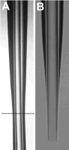
Photomicrographs of etched silica emitters. Additional description is in the text.
Figure 3
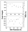
ESI performance for 5 μM reserpine at 5 nL/min (top) and 50 nL/min (bottom). Open circles refer to peak height (arbitrary units, left axes), and closed circles correspond to %RSD (right axes). The solvent was 99% water, 1% HAc.
Figure 4
ESI-MS reproducibility for 5 μM reserpine with three 5-μm-i.d. emitters. Open shapes indicate reserpine intensity vs. ESI voltage for the different emitters (left axis). Closed circles refer to %RSD of peak height for the replicates. The flow rate was 50 nL/min and the solvent was 99% water, 1% HAc.
Figure 5
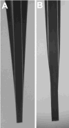
Photomicrographs of etched ESI emitters containing (A) silica and (B) polymer monoliths. The capillaries in both (A) and (B) were 360 lm o.d. and 50 lm i.d.
Similar articles
- Array of chemically etched fused-silica emitters for improving the sensitivity and quantitation of electrospray ionization mass spectrometry.
Kelly RT, Page JS, Tang K, Smith RD. Kelly RT, et al. Anal Chem. 2007 Jun 1;79(11):4192-8. doi: 10.1021/ac062417e. Epub 2007 May 2. Anal Chem. 2007. PMID: 17472340 - New method for fabrication of fused silica emitters with submicrometer orifices for nanoelectrospray mass spectrometry.
Ek P, Roeraade J. Ek P, et al. Anal Chem. 2011 Oct 15;83(20):7771-7. doi: 10.1021/ac201308n. Epub 2011 Sep 22. Anal Chem. 2011. PMID: 21939240 - Design and performance of a sheathless capillary electrophoresis/mass spectrometry interface by combining fused-silica capillaries with gold-coated nanoelectrospray tips.
Kele Z, Ferenc G, Klement E, Tóth GK, Janáky T. Kele Z, et al. Rapid Commun Mass Spectrom. 2005;19(7):881-5. doi: 10.1002/rcm.1866. Rapid Commun Mass Spectrom. 2005. PMID: 15724233 - A review of nanoelectrospray ionization applications for drug metabolism and pharmacokinetics.
Wickremsinhe ER, Singh G, Ackermann BL, Gillespie TA, Chaudhary AK. Wickremsinhe ER, et al. Curr Drug Metab. 2006 Dec;7(8):913-28. doi: 10.2174/138920006779010610. Curr Drug Metab. 2006. PMID: 17168691 Review. - Supercritical water-treated fused silica capillaries in analytical separations: Status review.
Karásek P, Horká M, Šlais K, Planeta J, Roth M. Karásek P, et al. J Chromatogr A. 2018 Mar 2;1539:1-11. doi: 10.1016/j.chroma.2018.01.051. Epub 2018 Jan 31. J Chromatogr A. 2018. PMID: 29397060 Review.
Cited by
- Top-Down Characterization of the Post-Translationally Modified Intact Periplasmic Proteome from the Bacterium Novosphingobium aromaticivorans.
Wu S, Brown RN, Payne SH, Meng D, Zhao R, Tolić N, Cao L, Shukla A, Monroe ME, Moore RJ, Lipton MS, Paša-Tolić L. Wu S, et al. Int J Proteomics. 2013;2013:279590. doi: 10.1155/2013/279590. Epub 2013 Mar 10. Int J Proteomics. 2013. PMID: 23555055 Free PMC article. - Unexpected diversity of signal peptides in prokaryotes.
Payne SH, Bonissone S, Wu S, Brown RN, Ivankov DN, Frishman D, Pasa-Tolić L, Smith RD, Pevzner PA. Payne SH, et al. mBio. 2012 Nov 20;3(6):e00339-12. doi: 10.1128/mBio.00339-12. mBio. 2012. PMID: 23169999 Free PMC article. - Uncovering Hidden Members and Functions of the Soil Microbiome Using De Novo Metaproteomics.
Lee JY, Mitchell HD, Burnet MC, Wu R, Jenson SC, Merkley ED, Nakayasu ES, Nicora CD, Jansson JK, Burnum-Johnson KE, Payne SH. Lee JY, et al. J Proteome Res. 2022 Aug 5;21(8):2023-2035. doi: 10.1021/acs.jproteome.2c00334. Epub 2022 Jul 6. J Proteome Res. 2022. PMID: 35793793 Free PMC article. - Enhanced ion utilization efficiency using an electrodynamic ion funnel trap as an injection mechanism for ion mobility spectrometry.
Clowers BH, Ibrahim YM, Prior DC, Danielson WF 3rd, Belov ME, Smith RD. Clowers BH, et al. Anal Chem. 2008 Feb 1;80(3):612-23. doi: 10.1021/ac701648p. Epub 2008 Jan 1. Anal Chem. 2008. PMID: 18166021 Free PMC article. - Nanowell-mediated multidimensional separations combining nanoLC with SLIM IM-MS for rapid, high-peak-capacity proteomic analyses.
Dou M, Chouinard CD, Zhu Y, Nagy G, Liyu AV, Ibrahim YM, Smith RD, Kelly RT. Dou M, et al. Anal Bioanal Chem. 2019 Aug;411(21):5363-5372. doi: 10.1007/s00216-018-1452-5. Epub 2018 Nov 5. Anal Bioanal Chem. 2019. PMID: 30397757 Free PMC article.
References
- Fenn JB, Mann M, Meng CK, Wong SF, Whitehouse CM. Mass Spectrom Rev. 1990;9:37–70.
- Smith RD, Shen Y, Tang K. Accounts Chem Res. 2004;37:269–278. - PubMed
- Simpson DC, Smith RD. Electrophoresis. 2005;26:1291–1305. - PubMed
- Wilm MS, Mann M. Int J Mass Spectrom Ion Processes. 1994;136:167–180.
- Wilm M, Mann M. Anal Chem. 1996;68:1–8. - PubMed
Publication types
MeSH terms
Substances
LinkOut - more resources
Full Text Sources
Other Literature Sources


