A bipedal DNA Brownian motor with coordinated legs - PubMed (original) (raw)
A bipedal DNA Brownian motor with coordinated legs
Tosan Omabegho et al. Science. 2009.
Abstract
A substantial challenge in engineering molecular motors is designing mechanisms to coordinate the motion between multiple domains of the motor so as to bias random thermal motion. For bipedal motors, this challenge takes the form of coordinating the movement of the biped's legs so that they can move in a synchronized fashion. To address this problem, we have constructed an autonomous DNA bipedal walker that coordinates the action of its two legs by cyclically catalyzing the hybridization of metastable DNA fuel strands. This process leads to a chemically ratcheted walk along a directionally polar DNA track. By covalently cross-linking aliquots of the walker to its track in successive walking states, we demonstrate that this Brownian motor can complete a full walking cycle on a track whose length could be extended for longer walks. We believe that this study helps to uncover principles behind the design of unidirectional devices that can function without intervention. This device should be able to fulfill roles that entail the performance of useful mechanical work on the nanometer scale.
Figures
Fig. 1
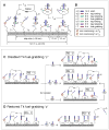
(A) Cartoon of the DX track structure with the walker on it. The walker is shown on stem-loops T1 and T2. The walker’s 5′-5′ link is denoted by two black dots, and its 3′ ends by half arrows. T16 denotes flexible poly-thymidine linkers on the walker and two fuel hairpins F1 and F2. Two T5 regions provide flexibility at the base of the track stem-loops. All the binding sites are labeled with lowercase letters and complementary sequences are capped with a bar. The two fuel-grabbing sequences f and c on T1 and T4 respectively are not functional. (B) Color-coding and names of the binding sites. (C) Transitions made with a non-functional T4 fuel-grabbing sequence c. The walker is programmed to take two steps from RS-1 to RS-3 with the addition of F1 and F2 simultaneously (middle transition). A single step is made from RS-1 to RS-2 with the addition of F1 alone (top transition). With the addition of F2 alone, the walker does not move, and only with the further addition of F1 does the walker make the transition from RS-1 to RS-3 (bottom transition). (D) With the T4 fuel-grabbing sequence c restored, the walker transitions to RS-4, incorporating another F1 into the track, thereby kicking L-O off of T3.
Fig. 2
Transition from RS-1 to RS-3. In 12 sequential frames, this cartoon depicts the biped taking 2 steps. The leading-leg L-O catalyzing the release of the trialing-leg L-E) is depicted in steps 6–10. Central to directionally biasing the biped, steps 3 and 9, show how the activated fuel strands are spatially restricted to act on the stem-loop 7 nm away rather than the stem-loop 21 nm away.
Fig. 3
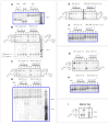
Psoralen crosslinking and 32P labeling. (A) A detailed picture of the UV activated psoralen crosslinking reaction between the track stem-loops and the walker. The psoralen on the stem-loops covalently links to the thymidines on the walker’s legs just outside the duplex formed by the stem-loops and the walker’s legs. (B) Visualizing the crosslink products with 32P. The three crosslinked products w-t (walker linked to the stem-loop on its trailing leg), w-l (walker linked to the stem-loop on its leading leg), and w-t-l (walker linked on both its trailing and leading leg) are shown forming in each experiment (W*, T1*, T2*, T3* and T4*) that they are visible for each resting state (RS-1, RS-2, RS-3, RS-4) of the system. The radioactive strand is drawn in bold red and the non-radioactive strands that are part of the crosslinked complex are drawn in bold blue. The constituent components of the products formed are listed in each box. (C) Denatured topologies and size of the three walker-stem-loop crosslink products w-t, w-l, and w-t-l.
Fig. 4
Autoradiogram analysis of the walking cycle. Non-denaturing gels (all 4%) are outlined in blue and super-denaturing gels (all 10%) are outlined in grey. Target products for the two states shown in each super-denaturing gel are drawn on the left and right hand side of each gel. The bands in the marker lanes that are labeled, are labeled by the number of nucleotides they correspond to. (A) Non-denaturing gel verifying formation of the track. The front half of the track (lanes 1–3) was annealed to the back half (lanes 4, 5) to make five species of the complete track or RS-1 (lanes 6–7) where only one strand was radioactive in each species. (B) Super-denaturing gel showing the walkers position in RS-1 at 0 hrs (lanes 3–7) and then in RS-2 (lanes 8–12) with the addition of F1 after 1 hour. [The box inside the gel outlines the walker-stem-loop crosslink products. See SOM text S6 and Fig. S7–S10 for a detailed explanation of the secondary products seen on the super-denaturing gels, as well as complete images of the super denaturing gels] (C) Super-denaturing gel verifying the transition to RS-3 (lanes 8–12) with the addition of F1 and F2, and no transition with no fuel added (lanes 3–7), both within an hour. (D) Non-denaturing gel verification of (B) and (C), showing the global state changes in the five experiments for RS-1 (lane 1), RS-2 (lanes 2–6) and RS-3 (lane 7–11). (E) Composite super-denaturing gel showing the track remained in RS-1 while sitting in solution with F2 for 1 hour (lanes 1–5), and then transitioned to RS-3 when F1 was added to the mixture (lanes). (Note: the grey line separates data from two different gels. (SOM Fig. S9)) (F) Non-denaturing gel of (E), showing co-localization of the RS-1 track with no fuel and the track in solution with F2, and then the transition to RS-3 when F1 was further added. (G) Super-denaturing gel verifying the transition to RS-4 (lanes 6–10) with the addition of F1 and F2, and verification that the system remained in RS-1 (lanes 3–7) with no fuel added (lanes), both within an hour. (H) Non-denaturing gel verification of (G), showing the global state changes in the five experiments for RS-1 (lane 1), RS-2 (lanes 2–6) and RS-4 (lane 7–11). (I) Marker gel showing the position of the w-t, w-l, and w-t-l products on a super-denaturing gel. [Complete pictures of the non-denaturing gels are outlined in SOM text S7 and Fig. S11].
Comment in
- Materials science. Building a better nano-biped.
Sherman W. Sherman W. Science. 2009 Apr 3;324(5923):46-7. doi: 10.1126/science.1172136. Science. 2009. PMID: 19342576 No abstract available.
Similar articles
- Coordinated chemomechanical cycles: a mechanism for autonomous molecular motion.
Green SJ, Bath J, Turberfield AJ. Green SJ, et al. Phys Rev Lett. 2008 Dec 5;101(23):238101. doi: 10.1103/PhysRevLett.101.238101. Epub 2008 Dec 3. Phys Rev Lett. 2008. PMID: 19113596 - Direct observation of stepwise movement of a synthetic molecular transporter.
Wickham SF, Endo M, Katsuda Y, Hidaka K, Bath J, Sugiyama H, Turberfield AJ. Wickham SF, et al. Nat Nanotechnol. 2011 Mar;6(3):166-9. doi: 10.1038/nnano.2010.284. Epub 2011 Feb 6. Nat Nanotechnol. 2011. PMID: 21297627 - A bipedal DNA motor that travels back and forth between two DNA origami tiles.
Liber M, Tomov TE, Tsukanov R, Berger Y, Nir E. Liber M, et al. Small. 2015 Feb 4;11(5):568-75. doi: 10.1002/smll.201402028. Epub 2014 Sep 18. Small. 2015. PMID: 25236793 - Dynamic DNA nanotechnology using strand-displacement reactions.
Zhang DY, Seelig G. Zhang DY, et al. Nat Chem. 2011 Feb;3(2):103-13. doi: 10.1038/nchem.957. Nat Chem. 2011. PMID: 21258382 Review. - Walking molecules.
von Delius M, Leigh DA. von Delius M, et al. Chem Soc Rev. 2011 Jul;40(7):3656-76. doi: 10.1039/c1cs15005g. Epub 2011 Mar 17. Chem Soc Rev. 2011. PMID: 21416072 Review.
Cited by
- Engineering DNA-based synthetic condensates with programmable material properties, compositions, and functionalities.
Do S, Lee C, Lee T, Kim DN, Shin Y. Do S, et al. Sci Adv. 2022 Oct 14;8(41):eabj1771. doi: 10.1126/sciadv.abj1771. Epub 2022 Oct 14. Sci Adv. 2022. PMID: 36240277 Free PMC article. - Development of the DNA-based biosensors for high performance in detection of molecular biomarkers: More rapid, sensitive, and universal.
Wang Q, Wang J, Huang Y, Du Y, Zhang Y, Cui Y, Kong DM. Wang Q, et al. Biosens Bioelectron. 2022 Feb 1;197:113739. doi: 10.1016/j.bios.2021.113739. Epub 2021 Oct 29. Biosens Bioelectron. 2022. PMID: 34781175 Free PMC article. Review. - A plasmonic nanorod that walks on DNA origami.
Zhou C, Duan X, Liu N. Zhou C, et al. Nat Commun. 2015 Aug 25;6:8102. doi: 10.1038/ncomms9102. Nat Commun. 2015. PMID: 26303016 Free PMC article. - Structural DNA nanotechnology: state of the art and future perspective.
Zhang F, Nangreave J, Liu Y, Yan H. Zhang F, et al. J Am Chem Soc. 2014 Aug 13;136(32):11198-211. doi: 10.1021/ja505101a. Epub 2014 Jul 28. J Am Chem Soc. 2014. PMID: 25029570 Free PMC article. Review. - A stochastic DNA walker that traverses a microparticle surface.
Jung C, Allen PB, Ellington AD. Jung C, et al. Nat Nanotechnol. 2016 Feb;11(2):157-63. doi: 10.1038/nnano.2015.246. Epub 2015 Nov 2. Nat Nanotechnol. 2016. PMID: 26524397 Free PMC article.
References
- Sherman WB, Seeman NC. Nano Lett. 2004;4:1203.
- Shin JS, Pierce NA. J Am Chem Soc. 2004;126:10834. - PubMed
- Tian Y, He Y, Chen Y, Yin P, Mao C. Angew Chem Int Edn. 2005;44:2. - PubMed
- Pei R, et al. J Am Chem Soc. 2006;128:12693. - PubMed
- Yin P, Choi HMT, Calvert CR, Pierce NA. Nature. 2008;451:318. - PubMed
Publication types
MeSH terms
Substances
LinkOut - more resources
Full Text Sources
Other Literature Sources


