A bilayered elastomeric scaffold for tissue engineering of small diameter vascular grafts - PubMed (original) (raw)
A bilayered elastomeric scaffold for tissue engineering of small diameter vascular grafts
Lorenzo Soletti et al. Acta Biomater. 2010 Jan.
Abstract
A major barrier to the development of a clinically useful small diameter tissue engineered vascular graft (TEVG) is the scaffold component. Scaffold requirements include matching the mechanical and structural properties with those of native vessels and optimizing the microenvironment to foster cell integration, adhesion and growth. We have developed a small diameter, bilayered, biodegradable, elastomeric scaffold based on a synthetic, biodegradable elastomer. The scaffold incorporates a highly porous inner layer, allowing cell integration and growth, and an external, fibrous reinforcing layer deposited by electrospinning. Scaffold morphology and mechanical properties were assessed, quantified and compared with those of native vessels. Scaffolds were then seeded with adult stem cells using a rotational vacuum seeding device to obtain a TEVG, cultured under dynamic conditions for 7 days and evaluated for cellularity. The scaffold showed firm integration of the two polymeric layers with no delamination. Mechanical properties were physiologically consistent, showing anisotropy, an elastic modulus (1.4 + or - 0.4 MPa) and an ultimate tensile stress (8.3 + or - 1.7 MPa) comparable with native vessels. The compliance and suture retention forces were 4.6 + or - 0.5 x 10(-4) mmHg(-1) and 3.4 + or - 0.3N, respectively. Seeding resulted in a rapid, uniform, bulk integration of cells, with a seeding efficiency of 92 + or - 1%. The scaffolds maintained a high level of cellular density throughout dynamic culture. This approach, combining artery-like mechanical properties and a rapid and efficient cellularization, might contribute to the future clinical translation of TEVGs.
Figures
Figure 1
ES-TIPS PEUU scaffold fabrication. A. The inner layer of the ES-TIPS PEUU scaffold is obtained by pouring hot polymer solution into a custom-made mold and rapidly freezing it to induce solvent-polymer phase separation (TIPS). B. After freeze drying, the resulting tubular scaffolds are mounted onto a mandrel in order to deposit an external micro-fibrous PEUU layer via electrospinning (ES). An intermediate sleeve between the TIPS scaffold and the mandrel is used to facilitate removal of the ES-TIPS scaffold at the end of the procedure.
Figure 2
Representative morphological assessment of the ID-4.7 ES-TIPS PEUU scaffold. A. Macroscopic appearance after electrospinning. B. Micrograph representing a cross-sectional portion of the compound scaffold. The arrow indicates the lumen. C. Interface between the two layers of the scaffold. D. Adhesion points (indicated by black arrow heads) in which electrospun fibers are fused with the pore structures of the TIPS.
Figure 3
Representative morphological assessment of the ID-1.3 ES-TIPS PEUU scaffold. A. Micrograph of the whole cross-section. Note the small luminal defect in the right portion of the scaffold due to sample processing (liquid nitrogen fracture). B. Increased magnification. The arrow indicates the lumen of the scaffold.
Figure 4
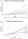
Stress-strain plots from uniaxial tensile testing of PEUU scaffolds. A. Circumferential and longitudinal uniaxial tensile properties of ID-4.7 ES-TIPS PEUU scaffolds (circles) and its two single components (i.e., TIPS PEUU (squares) and ES PEUU (triangles), respectively). Note the ES-TIPS material properties fall between those of its two individual components. (TIPS PEUU: n = 3; ES PEUU: n = 5; ES-TIPS PEUU: n = 3) B. Circumferential (dark grey) and longitudinal (light grey) uniaxial tensile properties of ID-4.7 scaffolds (mean ± standard deviation) along the complete testing range. The scaffold shows significant anisotropy (p<0.05; n = 3) with stiffer and stronger mechanical properties in the longitudinal direction. The level of strain to failure is comparable in the two directions. Note the level of breaking strain for the ES-TIPS scaffolds being approximately 500% of the initial sample length.
Figure 5
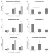
Summary of mechanical properties based on uniaxial tensile testing of PEUU scaffolds and native blood vessels. A. Comparison of strength among the three different PEUU scaffolds. The dashed bars indicate the absence of statistical significance between two groups; all the other comparisons are statistically significant (p < 0.05) (TIPS PEUU: n = 3; ES PEUU: n = 5; ES-TIPS PEUU: n = 3). B. Comparison of circumferential UTS between ES-TIPS PEUU scaffolds and native vessels. The plain bar indicates statistically significant difference (p < 0.05) between two groups; all the other comparisons are not statistically significant. (ES-TIPS PEUU: n = 3; hSV: n = 4; pIMA: n = 6). C. Strain to failure results from uniaxial tensile tests for the three different PEUU scaffolds. D. Comparison of circumferential STF between ES-TIPS PEUU scaffolds and native vessels. E. Approximated elastic modulus for the three different PEUU scaffolds. F. Comparison of approximated circumferential elastic modulus between the ES-TIPS scaffolds and the native vessels.
Figure 6
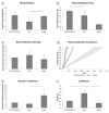
Summary of mechanical properties based on pressurization of ES-TIPS scaffolds and native blood vessels. A. Comparison of burst pressure between ES-TIPS PEUU scaffolds and native vessels. The plain bar indicates statistically significant difference between two groups (p < 0.05); all the other comparisons are not statistically significant. (ES-TIPS PEUU: n = 3; hSV: n = 4; pIMA: n = 6). B. Comparison of suture retention force between the ES-TIPS PEUU and native vessels. The dashed bar indicates absence of statistically significant difference (p < 0.05) between two groups; all the other comparisons are statistically significant. C. Comparison of suture retention strength between ES-TIPS PEUU and native vessels. None of the differences are statistically significant. D. Comparison of P-D curves between ES-PEUU scaffolds and native vessels. These results are presented as average ± SEM. E. Comparison of dynamic compliance between ES-TIPS PEUU scaffolds and native vessels. F. Comparison of β stiffness between the ES-TIPS PEUU scaffolds and the native vessels.
Figure 7
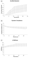
Geometrical and mechanical properties of the ID-4.7 ES-TIPS PEUU scaffold measured throughout a 24 h period of perfusion under physiological arterial conditions presented as mean ± SEM; n = 3; no significant differences were detected between any time points). A. Percent variation of average external diameter from the initial value (i.e., measured at time 0) for the ID-4.7 scaffold during perfusion ex vivo. B. Dynamic compliance. C. β stiffness.
Figure 8
Representative cell density of the ID-4.7 (A) and ID-1.3 (B) scaffolds 2 h after seeding (n=3). Blue=nuclei, green=F-actin, red=scaffold. Insets. Grayscale micrographs of the seeded scaffolds stained with H&E. Note the extent of the TIPS and ES layers. Scale bar = 100 μm. The arrows indicate the luminal surface of the scaffolds.
Figure 9
Dynamic culture results for the rat MSCS-incorporated ID-1.3 ES-TIPS PEUU scaffolds. A. Representative qualitative results after 2 h of static culture. B. Results after 3 days of dynamic culture. C. Results after 7 days of dynamic culture. The plain arrows indicate the luminal surface. Blue = nuclei, green = F-actin, red = scaffold. Images taken at 100X. The dashed orange arrow indicates a tissue-like cluster of cells detaching from the luminar surface of the scaffold after 7 days of dynamic culture. D. Image-base quantification of cell density into ES-TIPS PEUU scaffolds at different time points. The bar indicates statistically significant difference between two groups (p < 0.05; n = 3); all the other comparisons are not statistically significant.
Similar articles
- A novel polymeric fibrous microstructured biodegradable small-caliber tubular scaffold for cardiovascular tissue engineering.
Dimopoulos A, Markatos DN, Mitropoulou A, Panagiotopoulos I, Koletsis E, Mavrilas D. Dimopoulos A, et al. J Mater Sci Mater Med. 2021 Mar 1;32(2):21. doi: 10.1007/s10856-021-06490-1. J Mater Sci Mater Med. 2021. PMID: 33649939 Free PMC article. - Bilayered scaffold for engineering cellularized blood vessels.
Ju YM, Choi JS, Atala A, Yoo JJ, Lee SJ. Ju YM, et al. Biomaterials. 2010 May;31(15):4313-21. doi: 10.1016/j.biomaterials.2010.02.002. Epub 2010 Feb 25. Biomaterials. 2010. PMID: 20188414 - Electrospun PET/PCL small diameter nanofibrous conduit for biomedical application.
Rahmati Nejad M, Yousefzadeh M, Solouk A. Rahmati Nejad M, et al. Mater Sci Eng C Mater Biol Appl. 2020 May;110:110692. doi: 10.1016/j.msec.2020.110692. Epub 2020 Jan 24. Mater Sci Eng C Mater Biol Appl. 2020. PMID: 32204006 - Biodegradable and biomimetic elastomeric scaffolds for tissue-engineered heart valves.
Xue Y, Sant V, Phillippi J, Sant S. Xue Y, et al. Acta Biomater. 2017 Jan 15;48:2-19. doi: 10.1016/j.actbio.2016.10.032. Epub 2016 Oct 22. Acta Biomater. 2017. PMID: 27780764 Review. - Biodegradable polyester elastomers in tissue engineering.
Webb AR, Yang J, Ameer GA. Webb AR, et al. Expert Opin Biol Ther. 2004 Jun;4(6):801-12. doi: 10.1517/14712598.4.6.801. Expert Opin Biol Ther. 2004. PMID: 15174963 Review.
Cited by
- Crosslinked urethane doped polyester biphasic scaffolds: Potential for in vivo vascular tissue engineering.
Dey J, Xu H, Nguyen KT, Yang J. Dey J, et al. J Biomed Mater Res A. 2010 Nov;95(2):361-70. doi: 10.1002/jbm.a.32846. J Biomed Mater Res A. 2010. PMID: 20629026 Free PMC article. - Electrospun vascular grafts with improved compliance matching to native vessels.
Nezarati RM, Eifert MB, Dempsey DK, Cosgriff-Hernandez E. Nezarati RM, et al. J Biomed Mater Res B Appl Biomater. 2015 Feb;103(2):313-23. doi: 10.1002/jbm.b.33201. Epub 2014 May 21. J Biomed Mater Res B Appl Biomater. 2015. PMID: 24846218 Free PMC article. - Medical Textiles as Vascular Implants and Their Success to Mimic Natural Arteries.
Singh C, Wong CS, Wang X. Singh C, et al. J Funct Biomater. 2015 Jun 30;6(3):500-25. doi: 10.3390/jfb6030500. J Funct Biomater. 2015. PMID: 26133386 Free PMC article. Review. - Pericyte-based human tissue engineered vascular grafts.
He W, Nieponice A, Soletti L, Hong Y, Gharaibeh B, Crisan M, Usas A, Peault B, Huard J, Wagner WR, Vorp DA. He W, et al. Biomaterials. 2010 Nov;31(32):8235-44. doi: 10.1016/j.biomaterials.2010.07.034. Epub 2010 Aug 3. Biomaterials. 2010. PMID: 20684982 Free PMC article. - In Vitro Mechanical Property Evaluation of Chitosan-Based Hydrogels Intended for Vascular Graft Development.
Aussel A, Montembault A, Malaise S, Foulc MP, Faure W, Cornet S, Aid R, Chaouat M, Delair T, Letourneur D, David L, Bordenave L. Aussel A, et al. J Cardiovasc Transl Res. 2017 Dec;10(5-6):480-488. doi: 10.1007/s12265-017-9763-z. Epub 2017 Jul 31. J Cardiovasc Transl Res. 2017. PMID: 28762052
References
- Rosamond W, Flegal K, Friday G, Furie K, Go A, Greenlund K, et al. Heart disease and stroke statistics--2007 update: a report from the American Heart Association Statistics Committee and Stroke Statistics Subcommittee. Circulation. 2007;115(5):e69–171. - PubMed
- Onuma Y, Daemen J, Kukreja N, Serruys P. Revascularization in the high-risk patient: multivessel disease. Minerva Cardioangiol. 2007;55:579–92. - PubMed
- U.S. Renal Data System, USRDS . 2008 Annual Data Report: Atlas of Chronic Kidney Disease and End-Stage Renal Disease in the United States. National Institutes of Health, National Institute of Diabetes and Digestive and Kidney Diseases; Bethesda, MD: 2008.
- Nowygrod R, Egorova N, Greco G, Anderson P, Gelijns A, Moskowitz A, et al. Trends, complications, and mortality in peripheral vascular surgery. J Vasc Surg. 2006;43:205–16. - PubMed
- Grigioni M, et al. Vascular Grafts: Experiment and Modeling. WIT Press; Boston: 2003. Biomechanics and Hemodynamics of Grafting.
Publication types
MeSH terms
Substances
LinkOut - more resources
Full Text Sources
Other Literature Sources


