Nanomaterials based on DNA - PubMed (original) (raw)
Review
Nanomaterials based on DNA
Nadrian C Seeman. Annu Rev Biochem. 2010.
Abstract
The combination of synthetic stable branched DNA and sticky-ended cohesion has led to the development of structural DNA nanotechnology over the past 30 years. The basis of this enterprise is that it is possible to construct novel DNA-based materials by combining these features in a self-assembly protocol. Thus, simple branched molecules lead directly to the construction of polyhedrons, whose edges consist of double helical DNA and whose vertices correspond to the branch points. Stiffer branched motifs can be used to produce self-assembled two-dimensional and three-dimensional periodic lattices of DNA (crystals). DNA has also been used to make a variety of nanomechanical devices, including molecules that change their shapes and molecules that can walk along a DNA sidewalk. Devices have been incorporated into two-dimensional DNA arrangements; sequence-dependent devices are driven by increases in nucleotide pairing at each step in their machine cycles.
Figures
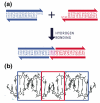
Figure 1. Sticky-Ended Cohesion. (a) Cohesion Between Two Molecular Overhangs
Two duplex molecules are shown, a red one and a blue one. Each has a single-stranded molecular overhang that is complementary to the overhang on the other molecule. When mixed, the two molecules can cohere in solution, as shown below. (b) Structural Features of Stick-Ended Cohesion. A crystal structure (6) is shown that contains DNA decamers whose cohesion in the direction of the helix axis is directed by dinucleotide sticky ends. This interaction is seen readily in the red box, where the continuity of the chains is interrupted by gaps. The two blue boxes contain B-form duplex DNA. It is a half-turn away from the DNA in the red box, so it is upside-down from it, but otherwise the structure is the same. Thus, sticky ends cohere to form B-DNA, and one can use this information in a predictive fashion to estimate the local structures of DNA constructs held together by sticky ends.
Figure 2. Self-Assembly of Branched DNA Molecules to Form Larger Arrangements
The image on the left shows a 4-arm branched junction made from four differently colored strands. Its double helical domains are tailed in 5′ sticky ends labeled (clockwise from the left) X, Y, X’ and Y’; the sticky ends are indicated by small extensions from the main strand (our convention is to represent 3′ ends by arrowheads or, as here, by half-arrowheads). The primed sticky ends complement the unprimed ones. The image on the right shows how four of these junctions can self-assemble through this complementarity to yield a quadrilateral. The sticky ends have come together in a complementary fashion. Note that this assembly does not use up all the available sticky ends, so that those that are left over could be used to generate a lattice in 2D, and, indeed, in 3D.
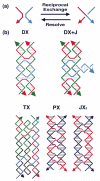
Figure 3. Motif Generation by Reciprocal Exchange
(a) The Fundamental Operation. The basic operation of reciprocal exchange is shown: A red stand and a blue strand become a red-blue and a blue-red strand following the operation. (b) Motifs that can result from Reciprocal Exchange of DNA Molecules. At the top of the panel are shown the DX motif and the DX+J motif. The DX motif results from two reciprocal exchanges between double helical motifs. The DX+J motif contains another DNA domain. Usually this domain is oriented perpendicular to the plane of the two helix axes in the DX part of the motif. When this orientation is achieved, the extra domain can behave as a topographic marker for 2D arrays containing the DX+J motif. The bottom row of the panel shows the TX motif at left, wherein a third domain has been added; again the exchanges take place between strands of opposite polarity. In the center and right are the PX motif and its topoisomer, the JX2 motif. The PX molecule is formed by exchanges between strands of identical polarity at every possible position. The JX2 molecule lacks two of these exchanges.
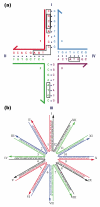
Figure 4
(a) Sequence Design. The four-arm junction shown contains four 16-mers that are each broken up into 13 overlapping tetramers. Insisting that each tetramer be unique and that no tetramer complement the those that flank the branch point leads to the formation of a stable branch, particularly if the twofold symmetry that enables branch migration is forbidden. Tetramers provide a ‘vocabulary’ of 256 (less 16 self-complementary units) possible sequences to use, leading to competition from trimers. It would be difficult to design this molecule to have 56 unique trimers. Larger units clearly are to be used with larger constructs. (b) A Twelve-Arm Junction. It is not possible to eliminate symmetry around the center of this junction, so identical nucleotide pairs were spaced at four-step intervals around the junction.
Figure 5. Early Topological Constructs Built from DNA
(a) A Cube-Like Molecule. This molecule is a hexacatenane; each edge corresponds to two double helical turns of DNA. Each backbone strand is drawn in a different color, and each one corresponds to a given face of the cube. Each is linked twice to each of the four strands that flank it, owing to the two-turn lengths of the edges. (b) A DNA Truncated Octahedron. This molecule is a 14-catenane, again with each edge consisting of two turns of double helical DNA. Although the truncated octahedron has 3 edges flanking each vertex (i.e., it is ‘3- connected’), it has been built using 4-arm junctions.
Figure 6. Atomic Force Micrographs of DNA Origami Constructs
(a) A Smiley Face. The scaffold strand, bound to helper strands, zigzags back and forth from left to right, yielding the structure seen. (b) A Map of the Western Hemisphere. This image demonstrates dramatically the addressability of the DNA array. Each of the white pixels is made by a small DNA double helical domain, similar to the DX+J tile (Figure 3).
Figure 7. Two-Dimensional Arrays of DX and DX+J Molecules
(a) An Alternating Array of DX and DX+J Molecules. Two tiles are shown, a DX tile labeled A and a DX+J tile labeled B*. The black dot represents the extra domain of the DX+J. Sticky ends are shown as geometrically complementary shapes. The array that would be formed by these two tiles is shown below them, including a stripe-like feature formed by the extra domain of the DX+J tile. The horizontal direction of each tile is 16 nm. The atomic force micrograph at right shows stripes separated by 32 nm. (b) An Array of Three DX and One DX+J Tiles. The A, B and C tiles are DX molecules and the D* tile is a DX+J tile. All tiles have the same dimensions as in (a). This should lead to a 64 nm separation of stripes, as seen in the atomic force micrograph at the right.
Figure 8. The 3D Lattice Formed by the Tensegrity Triangles
(a) The Surroundings of an Individual Triangle. This stereoscopic simplified image distinguishes the three independent directions by the colors (red, green and yellow) of their base pairs. Thus, the central triangle is shown flanked by three other pairs of triangles in the three differently colored directions. (b) The Rhombohedral Cavity Formed by the Tensegrity Triangles. This stereoscopic projection shows seven of the eight tensegrity triangles that comprise the corners of the rhombohedron. The outline of the cavity is shown in white. The red triangle at the back connects through one edge each to the three yellow triangles that lie in a plane somewhat closer to the viewer. The yellow triangles are connected through two edges each to two different green triangles that are in a plane even nearer the viewer. A final triangle that would cap the structure has been omitted for clarity. That triangle would be directly above the red triangle, and would be even closer to the viewer than the green triangles.
Figure 9. Organizing Gold Nanoparticles with a 2D Motif
(a) Two different 3D-DX motifs, containing 5 nm or 10 nm particles on one end of a propagation direction yield a checkerboard nanoparticle array. (b) The two 3D-DX motifs in greater detail assembled to form a 2D array. (c) A TEM image showing a checkerboard array of gold nanoparticles.
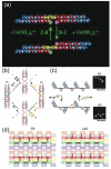
Figure 10. DNA-Based Nanomechanical Devices
(a) A DNA Nanomechanical Device Based on the B-Z Transition. The device consists of two DX molecules connected by a shaft containing 20 nucleotide pairs (yellow) capable of undergoing the B-Z transition. Under B-promoting conditions the short domains are on the same side of the shaft, but under Z-promoting conditions (added Co(NH ) 3+ 3 6 ) they are on opposite sides of the shaft. The pink and green FRET pair are used to monitor this change. (b) The Machine Cycle of a PX-JX2 Device. Starting with the PX device on the left, the green set strands are removed by their complements (Process I) to leave an unstructured frame. The addition of the yellow set strands (process II) converts the frame to the JX2 structure, in which the top and bottom domains are rotated a half turn relative to their arrangement in the PX conformation. Processes III and IV reverse this process to return to the PX structure. (c) AFM Demonstration of the Operation of the Device. A series of DNA trapezoids are connected by devices. In the PX state, the trapezoids are in a parallel arrangement, but when the system is converted to the JX2 state, they are in a zigzag arrangement. (d) Insertion of a Device Cassette into a 2D Array. The eight TX tiles that form the array are shown in differently colored outlined tiles. For clarity the cohesive ends are shown to be the same geometrical shape, although they all contain different sequences. The domain connecting the cassette to the lattice is not shown. The cassette and reporter helix are shown as red filled components; the marker tile is labeled ‘M’ and is shown with a black filled rectangle representing the domain of the tile that protrudes from the rest of the array. Both the cassette and the marker tile are rotated about 103° from the other components of the array (three nucleotides rotation). The PX arrangement is shown at the left and the JX2 arrangement is on the right. Note that the reporter hairpin points towards the marker tile in the PX state, but points away from it in the JX2 state.
Similar articles
- Construction of three-dimensional stick figures from branched DNA.
Seeman NC. Seeman NC. DNA Cell Biol. 1991 Sep;10(7):475-86. doi: 10.1089/dna.1991.10.475. DNA Cell Biol. 1991. PMID: 1892564 Review. - Dynamic patterning programmed by DNA tiles captured on a DNA origami substrate.
Gu H, Chao J, Xiao SJ, Seeman NC. Gu H, et al. Nat Nanotechnol. 2009 Apr;4(4):245-8. doi: 10.1038/nnano.2009.5. Epub 2009 Feb 15. Nat Nanotechnol. 2009. PMID: 19350035 Free PMC article. - An overview of structural DNA nanotechnology.
Seeman NC. Seeman NC. Mol Biotechnol. 2007 Nov;37(3):246-57. doi: 10.1007/s12033-007-0059-4. Epub 2007 Jul 12. Mol Biotechnol. 2007. PMID: 17952671 Free PMC article. Review. - Surface-assisted DNA self-assembly: An enzyme-free strategy towards formation of branched DNA lattice.
Bhanjadeo MM, Nayak AK, Subudhi U. Bhanjadeo MM, et al. Biochem Biophys Res Commun. 2017 Apr 1;485(2):492-498. doi: 10.1016/j.bbrc.2017.02.024. Epub 2017 Feb 9. Biochem Biophys Res Commun. 2017. PMID: 28189681 - Biochemistry and structural DNA nanotechnology: an evolving symbiotic relationship.
Seeman NC. Seeman NC. Biochemistry. 2003 Jun 24;42(24):7259-69. doi: 10.1021/bi030079v. Biochemistry. 2003. PMID: 12809482
Cited by
- Ionic conductivity, structural deformation, and programmable anisotropy of DNA origami in electric field.
Li CY, Hemmig EA, Kong J, Yoo J, Hernández-Ainsa S, Keyser UF, Aksimentiev A. Li CY, et al. ACS Nano. 2015 Feb 24;9(2):1420-33. doi: 10.1021/nn505825z. Epub 2015 Jan 30. ACS Nano. 2015. PMID: 25623807 Free PMC article. - Expanding the rule set of DNA circuitry with associative toehold activation.
Chen X. Chen X. J Am Chem Soc. 2012 Jan 11;134(1):263-71. doi: 10.1021/ja206690a. Epub 2011 Dec 14. J Am Chem Soc. 2012. PMID: 22129141 Free PMC article. - Biosensors with built-in biomolecular logic gates for practical applications.
Lai YH, Sun SC, Chuang MC. Lai YH, et al. Biosensors (Basel). 2014 Aug 27;4(3):273-300. doi: 10.3390/bios4030273. eCollection 2014 Sep. Biosensors (Basel). 2014. PMID: 25587423 Free PMC article. Review. - Interenzyme substrate diffusion for an enzyme cascade organized on spatially addressable DNA nanostructures.
Fu J, Liu M, Liu Y, Woodbury NW, Yan H. Fu J, et al. J Am Chem Soc. 2012 Mar 28;134(12):5516-9. doi: 10.1021/ja300897h. Epub 2012 Mar 16. J Am Chem Soc. 2012. PMID: 22414276 Free PMC article. - Engineering living functional materials.
Chen AY, Zhong C, Lu TK. Chen AY, et al. ACS Synth Biol. 2015 Jan 16;4(1):8-11. doi: 10.1021/sb500113b. ACS Synth Biol. 2015. PMID: 25592034 Free PMC article.
References
- Voet D, Rich A. The crystal structures of purines, pyrimidines and their intermolecular complexes. Prog. Nucl. Acid. Res. & Mol. Biol. 1970;10:183–265. - PubMed
- Watson JD, Crick FHC. Molecular structure of nucleic acids - a structure for deoxyribose nucleic acid. Nature. 1953;171:737–8. - PubMed
- Rich A, Davies DR. A new, 2-stranded helical structure, polyadenylic acid and polyuridylic acid. J. Am. Chem. Soc. 1956;78:3548–9.
- Yin P, Choi HMT, Calvert CR, Pierce NA. Programming biomolecular self-assembly pathways. Nature. 2008;451:318–23. - PubMed
Publication types
MeSH terms
Substances
LinkOut - more resources
Full Text Sources
Other Literature Sources
Miscellaneous


