NeuroML: a language for describing data driven models of neurons and networks with a high degree of biological detail - PubMed (original) (raw)
. 2010 Jun 17;6(6):e1000815.
doi: 10.1371/journal.pcbi.1000815.
Sharon Crook, Robert C Cannon, Michael L Hines, Guy O Billings, Matteo Farinella, Thomas M Morse, Andrew P Davison, Subhasis Ray, Upinder S Bhalla, Simon R Barnes, Yoana D Dimitrova, R Angus Silver
Affiliations
- PMID: 20585541
- PMCID: PMC2887454
- DOI: 10.1371/journal.pcbi.1000815
NeuroML: a language for describing data driven models of neurons and networks with a high degree of biological detail
Padraig Gleeson et al. PLoS Comput Biol. 2010.
Abstract
Biologically detailed single neuron and network models are important for understanding how ion channels, synapses and anatomical connectivity underlie the complex electrical behavior of the brain. While neuronal simulators such as NEURON, GENESIS, MOOSE, NEST, and PSICS facilitate the development of these data-driven neuronal models, the specialized languages they employ are generally not interoperable, limiting model accessibility and preventing reuse of model components and cross-simulator validation. To overcome these problems we have used an Open Source software approach to develop NeuroML, a neuronal model description language based on XML (Extensible Markup Language). This enables these detailed models and their components to be defined in a standalone form, allowing them to be used across multiple simulators and archived in a standardized format. Here we describe the structure of NeuroML and demonstrate its scope by converting into NeuroML models of a number of different voltage- and ligand-gated conductances, models of electrical coupling, synaptic transmission and short-term plasticity, together with morphologically detailed models of individual neurons. We have also used these NeuroML-based components to develop an highly detailed cortical network model. NeuroML-based model descriptions were validated by demonstrating similar model behavior across five independently developed simulators. Although our results confirm that simulations run on different simulators converge, they reveal limits to model interoperability, by showing that for some models convergence only occurs at high levels of spatial and temporal discretisation, when the computational overhead is high. Our development of NeuroML as a common description language for biophysically detailed neuronal and network models enables interoperability across multiple simulation environments, thereby improving model transparency, accessibility and reuse in computational neuroscience.
Conflict of interest statement
The authors have declared that no competing interests exist.
Figures
Figure 1. Relationship between the three Levels of NeuroML and MorphML, ChannelML and NetworkML.
Level 1 incorporates MorphML, which allows descriptions of cell structure ranging from single compartment cells to detailed cells based on morphological reconstructions. Metadata describing the provenance of the data (authors, citations, etc.) can be used at this and subsequent Levels. Level 2 builds on Level 1 to specify the passive properties and the location and densities of active conductances on the cell, and includes ChannelML, for description of the membrane processes that generate the electrophysiological behavior of cells. Level 3 contains NetworkML, allowing networks of these neuronal models and their synaptic connections to be described. MorphML, ChannelML and NetworkML can be used in isolation to describe model components, while a Level X file can include any elements from that and any lower Level.
Figure 2. Relationship between experimental data and model components expressed in NeuroML.
Experimental neuroscience data is measured at different scales describing subcellular, cellular and network properties and NeuroML provides a framework to describe models developed using this data at all of these levels. Once models are defined in NeuroML they can either be directly imported into a simulator or translated via a metasimulator like neuroConstruct. Optimization of such data-driven models involves an iterative process of experimentation, creation of models, comparison with data and refinement of models, and suggestions for new experiments based on modeling results.
Figure 3. XML structure of a ChannelML file and mappings to text and graphs.
(A) A ChannelML file containing a Hodgkin-Huxley type K+ conductance model, with four instances of a gating mechanism with open and closed states, and the rates of transitions between them. Supporting Text S1 contains a description of each of the elements contained in this file, and section 10.2 of that document outlines in more detail the equations behind a channel model expressed in ChannelML. (B) A section of a HTML page automatically generated from the ChannelML using an XML Stylesheet (XSL) file. (C) Top: plots of the forward (alpha, black) and reverse (beta, red) transition rates. Bottom: the time constant (tau) of the transition (black) and steady state of the gating variable (inf, red). These views of the contents of the ChannelML file can be generated automatically (e.g. by neuroConstruct) for any valid file.
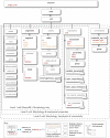
Figure 4. Elements for representing cells in NeuroML Levels 1-3.
The main element for expressing a branching neuronal structure in NeuroML is cell which is used for all Levels in NeuroML. The core of the cell description is a set of segment elements which describe the 3D shape of the cell. These can be grouped into cables which represent unbranched neurites of the cell. Metadata present in the cell description can contain details of the creators of the cell model, or the data on which it was based (e.g. a neuronal reconstruction from NeuroMorpho.org). Addition of the biophysics element allows a Level 2 conductance based spiking cell model to be described, and the connectivity element can be used for the allowed synaptic connectivity of a Level 3 cell (e.g. to be used when connecting the cell in a network). A detailed description of each of these elements can be found in Supporting Text S1. Only the elements in Level 1 which are normally used in compartmental cell modeling are shown in the figure. Other elements such as freePoints, features etc. could be present in a Level 1 file from a camera lucida reconstruction .
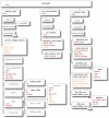
Figure 5. Elements in ChannelML.
ChannelML allows expression of models of voltage (and ligand) gated conductances which are dispersed across the cell membrane (in channel_type element), conductances which are concentrated at synaptic contacts (in synapse_type element) and basic models of time varying internal ion concentrations (in ion_concentration element). Distributed conductance descriptions contain a number of gate elements, which describe the transitions between conducting and non conducting states of the channels underlying the conductances. A number of synaptic conductance models are allowed including simple double exponential waveforms, AMPA and NMDA receptor mediated synapses, Short Term Plasticity (STP) models, Spike Timing Dependent Plasticity (STDP) models, and electrical synapses. The ion_concentration element can be used for the simple models of exponentially decaying Ca2+ pools often used in detailed cell models. A detailed description of each of these elements can be found in Supporting Text S1.
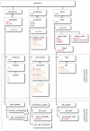
Figure 6. Elements in NetworkML.
The core elements for expressing networks are population for homogenous groups of cells positioned in 3D, projections for synaptic contacts between (or within) populations and inputs for electrical stimulation to the network. The networks can either be expressed as lists of precise positions, connections and input locations (instance based representation) or as templates for generating these lists (template based representation). A detailed description of each of these elements can be found in Supporting Text S1.
Figure 7. CA1 pyramidal cell model with non-uniform active conductances (based on Migliore et al.[2]).
(A) Top: cell morphology visualized in neuroConstruct with color scale showing the density of h-type (HCN) channels (yellow lower, red higher). Bottom: voltage traces (in response to a current pulse input at the soma) at 5 different locations in the cell after execution on NEURON (gray), GENESIS (red), MOOSE (blue) and PSICS (green). (B) Voltage map of same cell executed on the NEURON simulator (top) and membrane potential traces (bottom) for the axon (black), soma (yellow) and 3 locations (green, blue, red) at increasing distances along the dendritic tree. (C) Recompartmentalized morphology visualized and run in GENESIS (top) with membrane potential traces (bottom, colors as for panel (B)). (D) Cell morphology visualized in PSICS using the ICING application (
, top). Inset shows a small section of dendrite and the locations of the individual ion channels. Membrane potential traces obtained with PSICS below, with colors as for panel (B). MOOSE does not have a native graphical interface at present. The simulation time step in all cases was 0.002 ms, and spatial discretisation is described in Materials and Methods.
Figure 8. Models of electrical and chemical synapses implemented in NeuroML.
(A) Voltage traces from a pair of gap junction coupled model cells (300 pS) during 0.19 nA current pulse injected into one of the cells. Blue indicates cell receiving current pulse and red shows gap junction coupled cell simulated in GENESIS. White overlapping dashes indicate the same model in NEURON. Black overlapping dashes indicate the same model in MOOSE. (B) Simulated EPSCs for a single compartment cell receiving synaptic input through an AMPA receptor only synapse at a membrane potential of −80 mV (red) and −20 mV (blue) in GENESIS. Again, the dashed lines indicate the equivalent NEURON (white) and MOOSE (black) simulations. (C) As B but for a single compartment cell receiving synaptic input through an NMDA receptor only synapse. (D) Short–term plasticity (STP) model : membrane potential of a postsynaptic cell receiving a regular presynaptic spike train for a synaptic connection exhibiting no STP (green, left), facilitation (red, middle) and depression (blue, right) implemented on the NEST (colored) and NEURON (white overlap) simulators.
Figure 9. Comparison of the behavior of NeuroML-based cortical and thalamic cell models run on NEURON, GENESIS and MOOSE simulators.
(A) Single compartment cell model containing all 22 active conductances present in the detailed cell models (Supporting Table S2), together with a passive conductance and a decaying calcium pool. Left plot shows the membrane potential response to a 80 pA current injection on NEURON (black), GENESIS (red) and MOOSE (green). Right plot shows the behavior on NEURON of the activation variables for the anomalous rectifier (thick black line), L-type Ca2+ (red) and persistent Na+ conductances (green) and the inactivation variable of the fast Na+ conductance (blue). White curve overlays show the corresponding GENESIS traces, and dashed lines show MOOSE traces. (B–E) 3D representations of four cell models from Traub et al. implemented in NeuroML, color indicates the density of fast sodium conductances on the cell membrane (red: high - yellow: low). Graphs show somatic membrane potential during current injections for: (B) regular spiking (RS) Layer 2/3 pyramidal cell; (C) superficial low threshold spiking (LTS) interneuron; (D) intrinsically bursting (IB) Layer 5 pyramidal cell; (E) nucleus reticularis thalami (nRT) cell (trace colors as for left panel of A). See Supporting Figure S3 for further details of these and the 6 other electrically distinct thalamic and cortical cell models converted to NeuroML.
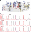
Figure 10. Comparison of the behavior of a NeuroML-based Layer 2/3 network model with 5 cell types connected with both electrical and chemical synaptic connections run on NEURON, GENESIS and MOOSE simulators.
The network is based on the larger network described in Cunningham et al. , and uses five of the cortical cell models converted to NeuroML from Traub et al. . (A) 20 regular spiking pyramidal cells (RS, blue), 6 fast rhythmic bursting pyramidal cells (FRB, black), 10 low threshold spiking interneurons (LTS, red), 10 axo-axonic interneurons (yellow) and 10 basket cells (brown) placed at random in a cylindrical region. The network contained electrical connections between the cells within each population, along with 4300 excitatory connections of 10 types within and between populations and 3800 inhibitory connections of 12 types (Supporting Table S4), but these are not shown. (B) Somatic membrane potential traces from 2 each of RS, FRB and LTS cells (with colors as in (A)) for simulations run on NEURON (top), GENESIS (middle) and MOOSE (bottom). Simulation time step was 0.001 ms.
Similar articles
- The NeuroML ecosystem for standardized multi-scale modeling in neuroscience.
Sinha A, Gleeson P, Marin B, Dura-Bernal S, Panagiotou S, Crook S, Cantarelli M, Cannon RC, Davison AP, Gurnani H, Silver RA. Sinha A, et al. Elife. 2025 Jan 10;13:RP95135. doi: 10.7554/eLife.95135. Elife. 2025. PMID: 39792574 Free PMC article. - NeuroML-DB: Sharing and characterizing data-driven neuroscience models described in NeuroML.
Birgiolas J, Haynes V, Gleeson P, Gerkin RC, Dietrich SW, Crook S. Birgiolas J, et al. PLoS Comput Biol. 2023 Mar 3;19(3):e1010941. doi: 10.1371/journal.pcbi.1010941. eCollection 2023 Mar. PLoS Comput Biol. 2023. PMID: 36867658 Free PMC article. - EDEN: A High-Performance, General-Purpose, NeuroML-Based Neural Simulator.
Panagiotou S, Sidiropoulos H, Soudris D, Negrello M, Strydis C. Panagiotou S, et al. Front Neuroinform. 2022 May 20;16:724336. doi: 10.3389/fninf.2022.724336. eCollection 2022. Front Neuroinform. 2022. PMID: 35669596 Free PMC article. - MorphML: level 1 of the NeuroML standards for neuronal morphology data and model specification.
Crook S, Gleeson P, Howell F, Svitak J, Silver RA. Crook S, et al. Neuroinformatics. 2007 Summer;5(2):96-104. doi: 10.1007/s12021-007-0003-6. Neuroinformatics. 2007. PMID: 17873371 Free PMC article. Review. - Towards NeuroML: model description methods for collaborative modelling in neuroscience.
Goddard NH, Hucka M, Howell F, Cornelis H, Shankar K, Beeman D. Goddard NH, et al. Philos Trans R Soc Lond B Biol Sci. 2001 Aug 29;356(1412):1209-28. doi: 10.1098/rstb.2001.0910. Philos Trans R Soc Lond B Biol Sci. 2001. PMID: 11545699 Free PMC article. Review.
Cited by
- TrakEM2 software for neural circuit reconstruction.
Cardona A, Saalfeld S, Schindelin J, Arganda-Carreras I, Preibisch S, Longair M, Tomancak P, Hartenstein V, Douglas RJ. Cardona A, et al. PLoS One. 2012;7(6):e38011. doi: 10.1371/journal.pone.0038011. Epub 2012 Jun 19. PLoS One. 2012. PMID: 22723842 Free PMC article. - Online conversion of reconstructed neural morphologies into standardized SWC format.
Mehta K, Ljungquist B, Ogden J, Nanda S, Ascoli RG, Ng L, Ascoli GA. Mehta K, et al. Nat Commun. 2023 Nov 16;14(1):7429. doi: 10.1038/s41467-023-42931-x. Nat Commun. 2023. PMID: 37973857 Free PMC article. - Application of a "staggered walk" algorithm for generating large-scale morphological neuronal networks.
Zito J, Memelli H, Horn KG, Solomon IC, Wittie LD. Zito J, et al. Comput Intell Neurosci. 2012;2012:876357. doi: 10.1155/2012/876357. Epub 2012 Sep 30. Comput Intell Neurosci. 2012. PMID: 23056037 Free PMC article. - A Modular Workflow for Model Building, Analysis, and Parameter Estimation in Systems Biology and Neuroscience.
Santos JPG, Pajo K, Trpevski D, Stepaniuk A, Eriksson O, Nair AG, Keller D, Hellgren Kotaleski J, Kramer A. Santos JPG, et al. Neuroinformatics. 2022 Jan;20(1):241-259. doi: 10.1007/s12021-021-09546-3. Epub 2021 Oct 28. Neuroinformatics. 2022. PMID: 34709562 Free PMC article. - Combining hypothesis- and data-driven neuroscience modeling in FAIR workflows.
Eriksson O, Bhalla US, Blackwell KT, Crook SM, Keller D, Kramer A, Linne ML, Saudargienė A, Wade RC, Hellgren Kotaleski J. Eriksson O, et al. Elife. 2022 Jul 6;11:e69013. doi: 10.7554/eLife.69013. Elife. 2022. PMID: 35792600 Free PMC article.
References
- Mainen ZF, Sejnowski TJ. Influence of dendritic structure on firing pattern in model neocortical neurons. Nature. 1996;382:363–366. - PubMed
- Kole MH, Ilschner SU, Kampa BM, Williams SR, Ruben PC, et al. Action potential generation requires a high sodium channel density in the axon initial segment. Nat Neurosci. 2008;11:178–186. - PubMed
- Jarsky T, Roxin A, Kath WL, Spruston N. Conditional dendritic spike propagation following distal synaptic activation of hippocampal CA1 pyramidal neurons. Nat Neurosci. 2005;8:1667–1676. - PubMed
Publication types
MeSH terms
Grants and funding
- 086699/WT_/Wellcome Trust/United Kingdom
- R01 NS011613/NS/NINDS NIH HHS/United States
- R01 MH081905/MH/NIMH NIH HHS/United States
- P01 DC04732/DC/NIDCD NIH HHS/United States
- R01 DC009977/DC/NIDCD NIH HHS/United States
- R01 MH086638/MH/NIMH NIH HHS/United States
- R01 NS11613/NS/NINDS NIH HHS/United States
- WT_/Wellcome Trust/United Kingdom
- BB/F005490/1/BB_/Biotechnology and Biological Sciences Research Council/United Kingdom
- G0400598/MRC_/Medical Research Council/United Kingdom
- P01 DC004732/DC/NIDCD NIH HHS/United States
- 0064413/BB_/Biotechnology and Biological Sciences Research Council/United Kingdom
LinkOut - more resources
Full Text Sources
Other Literature Sources


