Ligand placement based on prior structures: the guided ligand-replacement method - PubMed (original) (raw)
Ligand placement based on prior structures: the guided ligand-replacement method
Herbert E Klei et al. Acta Crystallogr D Biol Crystallogr. 2014 Jan.
Abstract
The process of iterative structure-based drug design involves the X-ray crystal structure determination of upwards of 100 ligands with the same general scaffold (i.e. chemotype) complexed with very similar, if not identical, protein targets. In conjunction with insights from computational models and assays, this collection of crystal structures is analyzed to improve potency, to achieve better selectivity and to reduce liabilities such as absorption, distribution, metabolism, excretion and toxicology. Current methods for modeling ligands into electron-density maps typically do not utilize information on how similar ligands bound in related structures. Even if the electron density is of sufficient quality and resolution to allow de novo placement, the process can take considerable time as the size, complexity and torsional degrees of freedom of the ligands increase. A new module, Guided Ligand Replacement (GLR), was developed in Phenix to increase the ease and success rate of ligand placement when prior protein-ligand complexes are available. At the heart of GLR is an algorithm based on graph theory that associates atoms in the target ligand with analogous atoms in the reference ligand. Based on this correspondence, a set of coordinates is generated for the target ligand. GLR is especially useful in two situations: (i) modeling a series of large, flexible, complicated or macrocyclic ligands in successive structures and (ii) modeling ligands as part of a refinement pipeline that can automatically select a reference structure. Even in those cases for which no reference structure is available, if there are multiple copies of the bound ligand per asymmetric unit GLR offers an efficient way to complete the model after the first ligand has been placed. In all of these applications, GLR leverages prior knowledge from earlier structures to facilitate ligand placement in the current structure.
Keywords: GLR; guided ligand-replacement method; ligand placement.
Figures
Figure 1
Overview of Guided Ligand Replacement (GLR) as implemented in Phenix. Core routines are outlined by short dashes. Inputs are outlined by long dashes. The top box lists input related to the target structure: (i) the apo model into which the ligand is to be placed (e.g. molecular-replacement solution), (ii) structure factors in order to generate an electron-density map for real-space refinement and (iii) ligand specification. The right box lists ways in which the structure of the reference protein–ligand complex can be obtained: (i) provide it directly, (ii) provide a directory of protein–ligand complexes to be searched, (iii) poll the Chemical Component Dictionary through the RCSB web service and (iv) a user-written query to another structural database (e.g. a proprietary database in the pharmaceutical industry). The functionality outlined by double lines is part of the Phenix distribution.
Figure 2
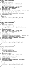
Examples of PHIL instructions for the three supported ways to arrive at the GLR reference structure (Fig. 1 ▶). (a) Provide explicitly. (b) Search provided directory. (c) Poll RCSB web service. As with other Phenix applications, arguments can also be provided on the command line. Online documentation for GLR can be found at
http://www.phenix-online.org/documentation/GLR.htm
.
Figure 3
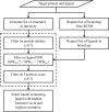
Two procedures were implemented to arrive at the reference structure when one is not explicitly specified: (i) search a provided directory and (ii) query the RCSB. While the number of structures to consider can be large, the steps outlined by the dashed box can optionally be performed in parallel. The molecular-weight filter requires each potential reference ligand (RL) to be similar in size to the input target ligand (TL).
Figure 4
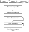
Overview of the matching algorithm used in eLBOW to associate analogous atoms in two molecules. The input consists of the two ligands in any accepted format (e.g. SDF). Unlike routines such as phenix.superpose_ligands, in GLR the match options are fixed and not exposed to the user through PHIL instructions. Both the matching of building blocks and the expansion of atom matches are iterative. These steps are repeated to generate the greatest number of atomic matches.
Figure 5
Schematic representation of three test cases, from simple to complex, in which the reference structure was used to place the ligand(s) in the target structure by GLR. The triangles labeled A and B represent protein molecules in the asymmetric unit. The black spheres and triangle with white dots represent ligands in the reference structures. The white spheres and triangles with black dots represent ligands in the target structures. In case 3 triangles rather than spheres were used to represent the ligands because when an asymmetric ligand is bound in an active site shared across a homomeric interface, an issue of directionality arises. The lower triangle associated with the target structure indicates the presence of an alternate ligand conformation with the reverse orientation.
Figure 6
Chemical structures of the ligands LGM, LGK, N4D, 38P and DR7 (atazanavir).
Figure 7
GLR progression for case 1 (FXa). (a) Superposition of the reference heavy chain (chain A; cyan) on the target heavy chain (chain A; yellow). This superposition places the reference ligand LGM (cyan) in the difference electron density for the target ligand LGK. While the fit to the electron density is reasonable, disagreement is apparent where the chemical structures of LGM and LGK differ. The red asterisk marks the location of the substituent change at C3 (IUPAC numbering) of the pyrazolopyridinonyl core from methyl to trifluromethyl. The yellow asterisk marks the location of the _o_-substituent change of the distal phenyl from _N_-methylpyrrolodyl to methylsulfonyl. (b) Placement of target ligand (green) in its electron density after graph theory was used to associate analogous atoms and adjust its conformation accordingly. The reference ligand (cyan) was carried forward from (a) for comparison. (c) Comparison of the _GLR_-placed target ligand (green) with the results from the final refinement (cyan).
Figure 8
Schematic of the informatics infrastructure used to automatically provide the GLR reference structure, if available, as one component of the refinement pipeline. Steps outlined with dashed lines are pre-calculated. Steps outlined with solid lines are calculated for the target ligand as part of the structure refinement. A procedure based on atom pairs was used to calculate the ligand fingerprints (Carhart et al., 1985 ▶). These digital fingerprints were then compared through their pairwise Tanimoto coefficient. A coefficient threshold of 0.7 was used because ligands with this degree of similarity were found to reliably bind in the expected fashion (i.e. with the same orientation and similar overall conformation). With diverse sets of ligands, it may be necessary to lower this threshold at the risk of false positives.
Similar articles
- Automating crystallographic structure solution and refinement of protein-ligand complexes.
Echols N, Moriarty NW, Klei HE, Afonine PV, Bunkóczi G, Headd JJ, McCoy AJ, Oeffner RD, Read RJ, Terwilliger TC, Adams PD. Echols N, et al. Acta Crystallogr D Biol Crystallogr. 2014 Jan;70(Pt 1):144-54. doi: 10.1107/S139900471302748X. Epub 2013 Dec 25. Acta Crystallogr D Biol Crystallogr. 2014. PMID: 24419387 Free PMC article. - E-novo: an automated workflow for efficient structure-based lead optimization.
Pearce BC, Langley DR, Kang J, Huang H, Kulkarni A. Pearce BC, et al. J Chem Inf Model. 2009 Jul;49(7):1797-809. doi: 10.1021/ci900073k. J Chem Inf Model. 2009. PMID: 19552372 - Efficient molecular docking of NMR structures: application to HIV-1 protease.
Huang SY, Zou X. Huang SY, et al. Protein Sci. 2007 Jan;16(1):43-51. doi: 10.1110/ps.062501507. Epub 2006 Nov 22. Protein Sci. 2007. PMID: 17123961 Free PMC article. - Conformational energy range of ligands in protein crystal structures: The difficult quest for accurate understanding.
Peach ML, Cachau RE, Nicklaus MC. Peach ML, et al. J Mol Recognit. 2017 Aug;30(8):10.1002/jmr.2618. doi: 10.1002/jmr.2618. Epub 2017 Feb 24. J Mol Recognit. 2017. PMID: 28233410 Free PMC article. Review. - Validation of Protein-Ligand Crystal Structure Models: Small Molecule and Peptide Ligands.
Pozharski E, Deller MC, Rupp B. Pozharski E, et al. Methods Mol Biol. 2017;1607:611-625. doi: 10.1007/978-1-4939-7000-1_25. Methods Mol Biol. 2017. PMID: 28573591 Review.
Cited by
- Automating crystallographic structure solution and refinement of protein-ligand complexes.
Echols N, Moriarty NW, Klei HE, Afonine PV, Bunkóczi G, Headd JJ, McCoy AJ, Oeffner RD, Read RJ, Terwilliger TC, Adams PD. Echols N, et al. Acta Crystallogr D Biol Crystallogr. 2014 Jan;70(Pt 1):144-54. doi: 10.1107/S139900471302748X. Epub 2013 Dec 25. Acta Crystallogr D Biol Crystallogr. 2014. PMID: 24419387 Free PMC article. - A protease-resistant Escherichia coli asparaginase with outstanding stability and enhanced anti-leukaemic activity in vitro.
Maggi M, Mittelman SD, Parmentier JH, Colombo G, Meli M, Whitmire JM, Merrell DS, Whitelegge J, Scotti C. Maggi M, et al. Sci Rep. 2017 Nov 3;7(1):14479. doi: 10.1038/s41598-017-15075-4. Sci Rep. 2017. PMID: 29101342 Free PMC article. - The solvent component of macromolecular crystals.
Weichenberger CX, Afonine PV, Kantardjieff K, Rupp B. Weichenberger CX, et al. Acta Crystallogr D Biol Crystallogr. 2015 May;71(Pt 5):1023-38. doi: 10.1107/S1399004715006045. Epub 2015 Apr 30. Acta Crystallogr D Biol Crystallogr. 2015. PMID: 25945568 Free PMC article. Review. - Macromolecular structure determination using X-rays, neutrons and electrons: recent developments in Phenix.
Liebschner D, Afonine PV, Baker ML, Bunkóczi G, Chen VB, Croll TI, Hintze B, Hung LW, Jain S, McCoy AJ, Moriarty NW, Oeffner RD, Poon BK, Prisant MG, Read RJ, Richardson JS, Richardson DC, Sammito MD, Sobolev OV, Stockwell DH, Terwilliger TC, Urzhumtsev AG, Videau LL, Williams CJ, Adams PD. Liebschner D, et al. Acta Crystallogr D Struct Biol. 2019 Oct 1;75(Pt 10):861-877. doi: 10.1107/S2059798319011471. Epub 2019 Oct 2. Acta Crystallogr D Struct Biol. 2019. PMID: 31588918 Free PMC article. - OOMMPPAA: a tool to aid directed synthesis by the combined analysis of activity and structural data.
Bradley AR, Wall ID, Green DV, Deane CM, Marsden BD. Bradley AR, et al. J Chem Inf Model. 2014 Oct 27;54(10):2636-46. doi: 10.1021/ci500245d. Epub 2014 Oct 9. J Chem Inf Model. 2014. PMID: 25244105 Free PMC article.
References
- Adams, P. D. et al. (2010). Acta Cryst. D66, 213–221. - PubMed
- Adams, P. D., Grosse-Kunstleve, R. W., Hung, L.-W., Ioerger, T. R., McCoy, A. J., Moriarty, N. W., Read, R. J., Sacchettini, J. C., Sauter, N. K. & Terwilliger, T. C. (2002). Acta Cryst. D58, 1948–1954. - PubMed
- Badger, J., Hansen, C., Hendle, J., Kissinger, C. R., Parlee, M. & Wasserman, S. (2005). Automated Determination of Protein:Ligand Structures from Image Data American Crystallographic Association Annual Meeting, Orlando, Florida, USA.
- Badger, J., Sauder, J. M. et al. (2005). Proteins, 60, 787–796. - PubMed
- Blundell, T. L., Jhoti, H. & Abell, C. (2002). Nature Rev. Drug Discov. 1, 45–54. - PubMed


