Molecular architecture of tailed double-stranded DNA phages - PubMed (original) (raw)
Review
. 2014 Jan 1;4(1):e28281.
doi: 10.4161/bact.28281. Epub 2014 Feb 21.
Affiliations
- PMID: 24616838
- PMCID: PMC3940491
- DOI: 10.4161/bact.28281
Review
Molecular architecture of tailed double-stranded DNA phages
Andrei Fokine et al. Bacteriophage. 2014.
Abstract
The tailed double-stranded DNA bacteriophages, or Caudovirales, constitute ~96% of all the known phages. Although these phages come in a great variety of sizes and morphology, their virions are mainly constructed of similar molecular building blocks via similar assembly pathways. Here we review the structure of tailed double-stranded DNA bacteriophages at a molecular level, emphasizing the structural similarity and common evolutionary origin of proteins that constitute these virions.
Keywords: Caudovirales; bacteriophage structure; phage proteins; phage tails; tailed double-stranded DNA bacteriophages; virus capsids; virus structure.
Figures
Figure 1. Structure of the Myoviridae phage T4 (left), Podoviridae phage φ29 (middle), and Siphiviridae phage TP901-1 (right). The left panel was reproduced from reference , the middle panel from reference , and the right panel from reference .
Figure 2. Schematic representation of the bacteriophage assembly. Reproduced from reference .
Figure 3. Structures of the phage terminases. (A) Ribbon diagram of the small terminase of phage Sf6. Different chains of the small terminase octamer are shown in a different colors. (B) Ribbon diagram of the large terminase protein, gp17, of phage T4. The N-terminal ATPase domain of T4_gp17 is subdivided into 2 subdomains marked N-subdomain I and II. N-subdomain I is in gold, N-subdomain II is in yellow, and the C-terminal nuclease domain is in cyan. (A) was reproduced from reference , (B) from reference .
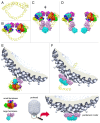
Figure 4. A model for packaging initiation by the small terminase (reproduced from ref. 47). Framed area: The small terminase subunits are represented in rainbow colors. The N-terminal ATPase domain of the large terminase is colored purple and the C-terminal nuclease domain cyan. (A) Packaging initiation sites on the phage genomic DNA. (B) Two small terminase oligomers bound to the initiation sites. (C) Two large terminase molecules are recruited and cleave the DNA backbones associated with the same base pair. The nuclease domain of the large terminase on the left-hand side is obscured by the 2-fold related nuclease domain of the large terminase on the right-hand side. (D) Two free ends are generated on the DNA, and further digestion is prevented by the small terminase. (E) The initiation complex binds to an empty procapsid. (F) Four more large terminase molecules are recruited to assemble the pentameric motor and rapid DNA translocation causes the dissociation of the small terminase.
Figure 5. DNA Packaging by the large T4 terminase (reproduced from ref. 48). The figure shows the sequence of events that occur in a single T4 gp17 molecule during packaging. The gp17 N-terminal subdomain I, subdomain II, and C-terminal domain are represented as green, yellow, and cyan ovals, respectively. The 5-pointed stars show the charge interactions between the N-terminal subdomain I and the C-terminal domain. The 4-pointed stars show the charge interaction between the N-terminal subdomain II and the C-terminal domain. The flexible linker between N- and C-terminal domains is represented by a wiggly cyan line. (A) The gp17 C-terminal domain is ready to bind DNA. (B) The C-terminal domain, when bound to the DNA, brings the DNA closer to the N-terminal domain of the same subunit. Conformational change in the N-terminal domain causes Arg162 to be placed into the ATPase active center in preparation for hydrolysis. (C) Hydrolysis of ATP has rotated the N-terminal subdomain II by about 6°, thereby aligning the charge pairs resulting in an electrostatic attraction that moves the C-terminal domain and the DNA 6.8 Å (equivalent to the distance between 2 base pairs) closer to the N-terminal domain and into the capsid. (D) ADP and Pi are released and the C-terminal domain returns to its original position. DNA is released and is aligned to bind the C-terminal domain of the neighboring gp17 subunit.
Figure 6. Structures of the portal proteins of phages SPP1 and P22. (A and B) display the top and side views of the SPP1 portal protein dodecamer, respectively. (C) Structure of the SPP1 portal protein monomer. (D) Side view of the P22 portal protein dodecamer. (A–C) were reproduced from reference , (D) from reference .
Figure 7. Structure of the bacteriophage HK97 major capsid protein shell. (A–C) correspond to the mature head. (D–F) correspond to the prohead. (A and D) display structures of the capsid protein subunits. (B and E) show entire heads and top views of capsid protein hexamers and pentamers. (C) and (F) show side views of capsid protein hexamers. (A) was reproduced from reference , (B–F) from ref. .
Figure 8. Structure of the bacteriophage T4 head (T = 13 / Q = 20 symmetry). (A) Shaded surface representation of the cryo-EM reconstruction viewed perpendicular to the 5-fold axis. The major capsid protein, gp23, is shown in blue, the special vertex protein, gp24, is in magenta, Soc is in white, Hoc is in yellow, and the portal vertex is in green. (B) Close up view of 2 gp23 capsomers corresponding to the rectangle outlined in black in (A). One Soc monomer is outlined by a blue ellipse; one Soc trimer is outlined by a red circle. The figure was modified from reference .
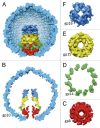
Figure 9. Structure of the bacteriophage T7 internal capsid core. The portal protein, gp8, is in red. The core proteins gp14, gp15, and gp16 are in green, yellow, and blue, respectively. (A and B) display side views of the core. (C and D) show top views of the core layers. (F) displays the top view of the portal protein. The figure was reproduced from reference .
Figure 10. Structure of the packaged DNA within phage capsids. (A and B) Organization of DNA in phage K1E, whose capsid contains an internal protein core. (A) displays a 75 Å thick slice containing the central section of the K1E cryo-EM map. Several DNA strands in the outermost layers are marked with black dots to emphasize their hexagonal packing. (B) shows the outermost layer of DNA, most proximal to the inner capsid wall. The observed DNA pattern is consistent with the coaxial spool model. (C) Organization of DNA in the T5 capsid which does not have the internal core. A cryo-EM image is shown of a T5 capsid. The hexagonal DNA monodomains are underlined, and positions of dislocation walls (DW) and twist walls (TW) are shown. The scale bar represents 250 Å. (A and B) were reproduced from reference , (C) from reference .
Figure 11. Structure of the bacteriophage SPP1 tail completion proteins. (A and B) display ribbon diagrams of SPP1_gp15 and SPP1_gp16 proteins, respectively. (C and D) show the portal protein (blue) and 2 rings formed by the tail completion proteins below the portal (magenta and green). Reproduced from reference .
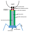
Figure 12. Schematic representation of a Myoviridae phage tail and neck. Siphoviridae phages would be missing the tail sheath (green) and the tail sheath terminator protein (red).
Figure 13. Tail tube and tail tube terminator proteins. (A) Structure of the N-terminal domain of the bacteriophage λ tail tube protein, gpV. This domain is necessary and sufficient for tail tube formation. (B) Structure of the tube protein Hcp1 from the bacterial secretion system VI. (C) Hexameric ring of Hcp1. (D) Structure of the tail tube terminator protein gpU of phage λ. (E) A hexameric ring of gpU. (A and B) were reproduced from reference . (C) was reproduced from reference .
Figure 14. Structure of the bacteriophage T4 tail in the extended (A) and contracted (B) conformations. Constituent proteins are shown in different colors. The contractile tail sheath is shown in green. (C) Structure of the tail sheath protein mutant, gp18M, containing 3 out of 4 domains of gp18. Domain I is in blue, domain II is in olive green, domain III is in orange red. Residues 454–470 and the last 27 C-terminal residues of gp18M are shown in cyan. (A) was reproduced from reference , (B) from reference , and (C) from reference .
Figure 15. Structure of the bacteriophage T4 baseplate and cell-puncturing device. (A) Cross-section view of the T4 baseplate. Constituent proteins are shown in different colors and are identified with their corresponding gene names. (B) Structure of the gp5-gp27 trimer is shown as a ribbon diagram in which each chain is shown in a different color. (C) Domains of gp27. The 2 homologous domains are colored in light green and cyan. These domains are similar to the tail-tube proteins. (D) The pseudohexameric ring formed by the tail-tube like domains of the gp27 trimer. (E) Schematic representation of a spike from the bacterial secretion system VI. The spike consists of the VgrG and PAAR-repeat proteins. (F) Structure of the PAAR-repeat protein. (A) was reproduced from reference . (B–D) were reproduced from reference . (E and F) were reproduced from reference .
Figure 16. Crystal structure of the phage p2 baseplate and its components. (A) View of the baseplate surface; ORF15 (Dit) is in green, ORF16 (Tal) is in red, and ORF18 (receptor binding protein) is in blue. The blue arrow indicates the position of the quasi 6-fold axis and points toward the rest of the phage tail and the capsid. (B) The baseplate has been rotated by 90° around the horizontal axis. The central channel formed by ORF15 hexamer is closed by the ORF16 trimeric dome. (C) The arrangement of ORF18 as 6 trimers. (D) Hexameric ORF15 (Dit). (E) Trimeric ORF16 (Tal). (F) View of ORF16 trimer rotated 180° relative to baseplate (B) with a different color for each subunit. (G) ORF15 hexamer is viewed in the same orientation as in (B). Each subunit, as well as the N- and C-terminus domains, have a different color. The central channel is ∼40 Å wide. (H) Ribbon view of the ORF15 (Dit) subunit. (I) Ribbon view of ORF16 (Tal) subunit. The 4 domains have been identified by D 1 to 4 and different colors of the β-strands. These domains correspond to those identified in gp27 from phage T4. (J) Ribbon view of the receptor-binding protein ORF18 trimer, with a different color for each chain. Reprinted from reference .
Figure 17. Tails of Podoviridae phages. (A) Cross-section view of the bacteriophage P22 tail-portal complex. The portal protein (gp1) is in red, the gp4 dodecamer is in magenta, the gp10 hexamer is in green, the tail spikes (trimers of gp13) are in blue, and the cell-puncturing needle (trimer of gp26) is in yellow. The barrel of the portal protein is not shown. Reproduced from reference . (B) Cross-section view of the bacteriophage T7 tail-portal complex. The portal, gp8, is in dark pink, the dodecamer of gp11 is in blue, the hexamer of gp12 is in cyan, parts of the fibers (gp17) are in gold. Reproduced from reference . (C) Central section of the bacteriophage φ29 cryo-EM reconstruction. The portal protein, gp10, is in magenta, the lower collar, gp11, is in yellow, the knob (gp9, gp13) is in orange. Reproduced from reference . (D) Ribbon diagram of the phage φ29 tail spike, gp12. The 3 polypeptide chains of the trimer are shown in blue, green, and orange, respectively. The structure contains domain 4 which is removed by an autocatalytic mechanism and is not present in the virion. Reproduced from reference .
Similar articles
- Tailed bacteriophages: the order caudovirales.
Ackermann HW. Ackermann HW. Adv Virus Res. 1998;51:135-201. doi: 10.1016/s0065-3527(08)60785-x. Adv Virus Res. 1998. PMID: 9891587 Free PMC article. Review. - Novel Bacteriophages in Enterococcus spp.
Mazaheri Nezhad Fard R, Barton MD, Heuzenroeder MW. Mazaheri Nezhad Fard R, et al. Curr Microbiol. 2010 Jun;60(6):400-6. doi: 10.1007/s00284-009-9555-z. Epub 2009 Dec 5. Curr Microbiol. 2010. PMID: 19967374 - Bacteriophage observations and evolution.
Ackermann HW. Ackermann HW. Res Microbiol. 2003 May;154(4):245-51. doi: 10.1016/S0923-2508(03)00067-6. Res Microbiol. 2003. PMID: 12798228 - A common evolutionary origin for tailed-bacteriophage functional modules and bacterial machineries.
Veesler D, Cambillau C. Veesler D, et al. Microbiol Mol Biol Rev. 2011 Sep;75(3):423-33, first page of table of contents. doi: 10.1128/MMBR.00014-11. Microbiol Mol Biol Rev. 2011. PMID: 21885679 Free PMC article. Review. - Automated classification of tailed bacteriophages according to their neck organization.
Lopes A, Tavares P, Petit MA, Guérois R, Zinn-Justin S. Lopes A, et al. BMC Genomics. 2014 Nov 27;15(1):1027. doi: 10.1186/1471-2164-15-1027. BMC Genomics. 2014. PMID: 25428721 Free PMC article.
Cited by
- The Life Cycle Transitions of Temperate Phages: Regulating Factors and Potential Ecological Implications.
Zhang M, Zhang T, Yu M, Chen YL, Jin M. Zhang M, et al. Viruses. 2022 Aug 28;14(9):1904. doi: 10.3390/v14091904. Viruses. 2022. PMID: 36146712 Free PMC article. Review. - Functional and Evolutionary Characterization of a Gene Transfer Agent's Multilocus "Genome".
Hynes AP, Shakya M, Mercer RG, Grüll MP, Bown L, Davidson F, Steffen E, Matchem H, Peach ME, Berger T, Grebe K, Zhaxybayeva O, Lang AS. Hynes AP, et al. Mol Biol Evol. 2016 Oct;33(10):2530-43. doi: 10.1093/molbev/msw125. Epub 2016 Jun 24. Mol Biol Evol. 2016. PMID: 27343288 Free PMC article. - Evolution of DNA packaging in gene transfer agents.
Esterman ES, Wolf YI, Kogay R, Koonin EV, Zhaxybayeva O. Esterman ES, et al. Virus Evol. 2021 Feb 19;7(1):veab015. doi: 10.1093/ve/veab015. eCollection 2021 Jan. Virus Evol. 2021. PMID: 33732503 Free PMC article. - Isolation and Characterization of Streptococcus mutans Phage as a Possible Treatment Agent for Caries.
Ben-Zaken H, Kraitman R, Coppenhagen-Glazer S, Khalifa L, Alkalay-Oren S, Gelman D, Ben-Gal G, Beyth N, Hazan R. Ben-Zaken H, et al. Viruses. 2021 May 2;13(5):825. doi: 10.3390/v13050825. Viruses. 2021. PMID: 34063251 Free PMC article. - Pantoea Bacteriophage vB_PagS_AAS23: A Singleton of the Genus Sauletekiovirus.
Žukauskienė E, Šimoliūnienė M, Truncaitė L, Skapas M, Kaupinis A, Valius M, Meškys R, Šimoliūnas E. Žukauskienė E, et al. Microorganisms. 2021 Mar 23;9(3):668. doi: 10.3390/microorganisms9030668. Microorganisms. 2021. PMID: 33807116 Free PMC article.
References
Publication types
LinkOut - more resources
Full Text Sources
Other Literature Sources


