Molecular architecture of the 40S⋅eIF1⋅eIF3 translation initiation complex - PubMed (original) (raw)
Molecular architecture of the 40S⋅eIF1⋅eIF3 translation initiation complex
Jan P Erzberger et al. Cell. 2014.
Erratum in
- Molecular Architecture of the 40S⋅eIF1⋅eIF3 Translation Initiation Complex.
Erzberger JP, Stengel F, Pellarin R, Zhang S, Schaefer T, Aylett CHS, Cimermančič P, Boehringer D, Sali A, Aebersold R, Ban N. Erzberger JP, et al. Cell. 2014 Nov 20;159(5):1227-1228. doi: 10.1016/j.cell.2014.11.001. Epub 2014 Nov 20. Cell. 2014. PMID: 28898626 Free PMC article. No abstract available.
Abstract
Eukaryotic translation initiation requires the recruitment of the large, multiprotein eIF3 complex to the 40S ribosomal subunit. We present X-ray structures of all major components of the minimal, six-subunit Saccharomyces cerevisiae eIF3 core. These structures, together with electron microscopy reconstructions, cross-linking coupled to mass spectrometry, and integrative structure modeling, allowed us to position and orient all eIF3 components on the 40S⋅eIF1 complex, revealing an extended, modular arrangement of eIF3 subunits. Yeast eIF3 engages 40S in a clamp-like manner, fully encircling 40S to position key initiation factors on opposite ends of the mRNA channel, providing a platform for the recruitment, assembly, and regulation of the translation initiation machinery. The structures of eIF3 components reported here also have implications for understanding the architecture of the mammalian 43S preinitiation complex and the complex of eIF3, 40S, and the hepatitis C internal ribosomal entry site RNA.
Copyright © 2014 Elsevier Inc. All rights reserved.
Figures
Graphical abstract
Figure 1
Domain Organization of S. cerevisiae eIF3 and Experimental Approach (A) Domain map of the six subunits of S. cerevisiae eIF3. Structured domains are shown as rectangles or spheres and are individually colored. Domains with known structural motifs are designated in the legend. Predicted unstructured regions are shown as thin gray lines. Known eIF3 interactions are indicated by arrows. Modules whose crystal structures are described in this paper are boxed, whereas previously described structures are indicated by narrow dashed lines. (B) Schematic outline of the hybrid experimental approach, highlighting the techniques used in this study.
Figure 2
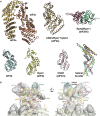
Structures and Interactions of S. cerevisiae eIF3 PCI-Domain Proteins (A) Cartoon representation of the crystal structure of the full PCI domain of eIF3a (chain A) with numbered helices. (B) Cartoon representation of the crystal structure of the eIF3a/eIF3c PCI dimer, colored as in Figure 1A and with numbered helices (with the exception of short 3/10 helices). (C) Comparison of PCI helical domains. The crystal structures of eIF3a (chain A) and eIF3c were aligned by superposition of their WHDs (colored blue) to each other and to Rpn6 (PDB
3TXN
, Pathare et al., 2012) and Thp1 (PDB
3T5V
-chain B, Ellisdon and Stewart, 2012), previously solved PCI proteins with extended helical domains (shown in red). Features of the eIF3a and eIF3c helical regions are labeled, and elements within eIF3c that stabilize the kink in the helical domain are shown in yellow. (D) Detail of the eIF3a/eIF3c interface. Conserved residues within the two interaction regions observed in the crystal structure are shown as spheres and labeled. Stronger green shading signifies a higher degree of conservation.
Figure S1
Comparison of WHD Interactions in eIF3a/eIF3c and Thp1/Sac3, Related to Figure 2 The WHDs of Thp1 and eIF3a were superposed, aligning their recognition helices. The positions of their partner proteins are offset by 6 Å, indicating a high degree of variability in WHD interactions within PCI-domain assemblies.
Figure 3
Docking of eIF3a/eIF3c in the PCI⋅MPN Core Density of Mammalian 43S and 43S⋅IRES EM Maps (A) Rigid-body fitting of the eIF3a/eIF3c PCI heterodimer model into the EM density of the 43S EM map. EIF3a and eIF3c are labeled and colored as in Figure 1A. Ribosomal proteins rpS1/eS1 (green) and rpS27/eS27 (blue) from the docked yeast 40S structure (Ben-Shem et al., 2011) are highlighted. Other ribosomal proteins are shown in gray and the ribosomal RNA in yellow. (B) Detail of the position of the eIF3a/eIF3c helical domains after rigid-body fitting and their proposed interaction with ribosomal proteins rpS1/eS1 (green), rpS27/eS27 (blue), and RNA expansion element ES7 (orange). (C) Rigid-body fitting of the eIF3a/eIF3c PCI heterodimer model into the 43S⋅IRES EM map. (D) Detail of the interaction between the CSFV-IRES and the eIF3a/eIF3c dimer in the docked structure. Residues of eIF3a and eIF3c important for IRES binding are shown as spheres and identified by their sequences. The dots indicate positions mutated in the equivalent human complex (Sun et al., 2013). RNA elements protected by eIF3 in IRES domain IIIB are shown as blue spheres and are identified by their sequences. The blue dots indicate extrahelical bases. (E) Model of the complete PCI⋅MPN core of eIF3 (based on currently available crystal structures and models) (Figure S2A) docked into the 43S⋅IRES EM map (Hashem et al., 2013b).
Figure S2
Individual Structures Used to Assemble the Mammalian eIF3 PCI⋅MPN Core, Related to Figure 3 The PCI-MPN model was assembled from the eIF3a/eIF3c PCI heterodimer presented in this paper, a hybrid of the helical domain of the partial CSN1 structure (PDB 4LCT) (Lee et al., 2013), with the missing WHD replaced by the rpS7 model from 26S EM structure (PDB 4B4T) (Beck et al., 2012) and the Rpn8/Rpn11 dimer model (PDB 4O8X) (Pathare et al., 2014) used to represent eIF3f/h. Additional models were the mammalian eIF3k structure (PDB 1RZ4) (Wei et al., 2004), the EM-fitted model of Rpn3 (PDB 4B4T) (Beck et al., 2012) and the structure of CSN7 (PDB 3CHM) (Dessau et al., 2008). Finally, the model for the helical bundle was derived from the model for the proteasome bundle (PDB 3J47) (Estrin et al., 2013).
Figure 4
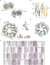
Structures of the eIF3b β Propeller and of the eIF3b-CTD/eIF3i/eIF3g-NTD Complex (A) Cartoon representation of the crystal structure of the middle domain of eIF3b (monomer A, unswapped). Individual blades are colored and labeled, and the position of the N and C termini are indicated. (B) Comparison of the β propeller diameters and pore dimensions among eight- (PDB
1R5M
, Cerna and Wilson, 2005), nine-, and ten-bladed (PDB
3F6K
, Quistgaard et al., 2009) β propellers. (C) Cartoon representation of the crystal structure of the eIF3b-CTD/eIF3i/eIF3g-NTD trimer, colored as in Figure 1A.
Figure S3
EIF3b β-Propeller Domain Swap, Conserved Structural Motif, and Alignment with eIF2A, Related to Figure 4 (A) Domain swap in the eIF3b β-propeller structure. (B) Detail of the swap - three strands from the invading domain complete the sheets in blades 1 and 9. (C) Conserved motif in the A-B loop region of individual eIF3b β-propeller blades. Inset - Superposition of all AB strands and LOGO depiction of conservation within a large number of eIF3b sequences. (D) Structure of TolB, which shares a similar motif in its linkages. (E) Multiple sequence alignment of eIF3b and eIF2A β-propeller domains, showing conserved residues in magenta. eIF2A shares the same number of blades and the conserved sequence motif (boxed) with eIF3b.
Figure S4
Details and Residues Conservation of eIF3i/eIF3g-NTD Interaction Surface, Related to Figure 4 (A–D) Details of the (A) first and (B) additional two conserved interaction elements between eIF3i (green) and eIF3g (purple). Residues of eIF3g and eIF3i involved in direct contacts are shown as sticks and labeled in green (eIF3i) or purple (eIF3g). Representative sequences from 40-organism alignments of (C) eIF3i and (D) the eIF3g-NTD, colored by percent conservation. Residues labeled in panels (A) and (B) are marked by spheres.
Figure 5
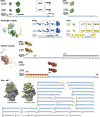
Single-Particle Reconstruction and CX-MS Analysis of the Yeast 40S⋅eIF1⋅eIF3 Complex (A and B) Views of EM reconstructions of the (A) unoccupied and (B) occupied fractions of the L. kluyveri 40S⋅eIF1⋅eIF3 complex sample with labeled ribosomal landmarks. (C) Matrix of all unique crosslinks between and within subunits of 40S from CX-MS analyses of multiple 40S⋅eIF1⋅eIF3 samples. Crosslinks were mapped onto the X-ray structure of the yeast 40S particle and were colored in green (crosslink distance <35 Å) or orange (crosslink distance >35 Å). The size of the circle for each mapped crosslink is proportional to its Id score. Multiple identifications of a particular crosslink are indicated by a stronger color intensity due to overlaid circles. (D) Scatter plot of mapped crosslink distances against Id score of the 40S data set. Crosslinks are grouped into three classes of similar size (high = Id score >36; medium = 32 < Id score < 36; and low = 28 < Id score < 32). Satisfied crosslinks (distance <35 Å) are within the green background. (E) Frequency distribution (as defined in Table S4) of detected unique crosslinked residues within the 40S matrix. Satisfied and violated crosslinks are colored as in (C).
Figure S5
Scatter Plots and Histograms of Crosslink Data, Related to Figure 5 (A) Scatter plot of mapped cross-link distances against the FDR rate for the 40S data set. Cross-links are grouped into three classes of roughly similar size. For FDR assignment into FDR < 0.05; 0.05 < FDR < 0.1 and 0.1 < FDR < 0.3; for Id-Score assessment cross-links were divided into High = Id-Score > 36; Medium = 32 < Id-Score < 36 and Low = 28 < Id-Score < 32. (B) Scatter plot of distances versus the Id-Score for interlinks of eIF3 with the 40S⋅eIF1 particle and links between and within different subunits of eIF3. Distances in this case were calculated average distances for the final set of solutions from our integrative modeling approach. (C) Distances of the same eIF3 data set plotted against the FDR rate. (D) Histogram of mapped distances of all cross-linked residues within the 40S data set versus their frequency. The 35 Å threshold is indicated as a red dotted line. It can be clearly seen that the vast majority of cross-linked residues spans a distances smaller than 35 Å and that those cross-linked residues bridging a larger distance follow no obvious pattern. (E) Histogram of distances against frequency for all cross-linked residues of eIF3 with the 40S⋅eIF1 particle and linked residues between and within different subunits of eIF3. In this case, we calculated average distances for the final set of solutions from our integrative modeling approach. The histogram shows a trend similar to the 40S data set.
Figure S6
Schematic of the Integrative Modeling Strategy, Related to Figure 6 Schematic of the integrative modeling approach highlighting the individual data inputs and the four stages in our modeling strategy.
Figure 6
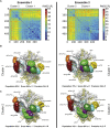
Integrative Modeling of the 40S⋅eIF1⋅eIF3 Complex (A) Representative example of one of our modeling solutions, showing the bead models used in our calculations. Domains of eIF3 are colored as in Figure 1A. (B) Matrix of unique crosslinks between eIF3 and the 40S⋅eIF1 particle and within subunits of eIF3. Intensity, size, and color code of crosslinked residues are as in Figure 5C. (C) Localization densities for eIF3 domains superposed on the unoccupied 40S EM reconstruction. The localization densities for each domain are contoured at 1.6 times their estimated molecular volumes. EIF3 domains are colored as in Figure 1A, and linker regions are labeled and colored gray. The position of eIF1 is indicated in brown. (D) Difference density of the occupied and unoccupied 40S⋅eIF1⋅eIF3 EM structures. The density is colored according to the positions of eIF3 domains given by the localization densities shown in (C).
Figure S7
Representation of the 40S⋅eIF1⋅eIF3 Subunits, Related to Figure 6 All subunits (eIF3b, eIF3i, eIF3j, eIF3g, eIF3a, eIF3c and 40S⋅eIF1) are represented by a set of beads, arranged into either rigid bodies corresponding to structured parts (blue segments in the bars, e.g., eIF3b β propeller) or flexible strings corresponding to unknown/disordered parts (yellow segments in the bars, e.g., eIF3c-NTD or eIF3a-CTD). The low resolution (10 residues per beads) and high resolution (1 residue per bead) representations are constrained together in the same rigid body. Furthermore, three interfaces are kept rigid (eIF3a/eIF3c PCI; eIF3b(655-699)/eIF3i/eIF3g(43-86); eiF3j(30-41)/eIF3b-RRM) as well as the structured parts of 40S⋅eIF1. In summary, the three resulting complexes (eIF3b/i/g/j, eIF3a/c and 40S⋅eIF1) are made of rigid domains and interfaces, connected by flexible linkers.
Figure S8
Localization Densities of the Ensemble of Solutions, Related to Figure 6 (A–C) The 180,000 sampled models were divided into two ensembles (left and right columns) and independently analyzed to assess the sampling convergence. The matrix of the rmsd (A) between all pairs of the 500 best-scoring models (solutions) indicates the presence of two clusters of similar structures. The color scale corresponds to the rmsd distance between structures in Å. The localization densities of cluster 1 (B) and cluster 2 (C) are contoured such that each volume represents 1.6 times the molecular volume of the corresponding domain. Cluster 1 and cluster 2 differ in the position of eIF3i. The precision values are calculated over all eIF3 subunits.
Figure 7
Placement and Interactions of eIF3 Components on 40S (A) (Left) Cartoon depiction of the 40S⋅eIF1 structure model, showing ribosomal proteins in gray and RNA in yellow. Proteins that are crosslinked to eIF3c are highlighted and labeled. The localization densities for the eIF3a/eIF3c PCI heterodimer and the eIF3c-NTD are shown as transparent densities and are colored as in Figure 1A. (Right) Schematic depiction of the crosslinking pattern of the eIF3c-NTD. The bead model of the eIF3c-NTD is shown as gray spheres linked by thin gray lines and is labeled with the residue range it represents. Interlinks are shown in gold and intralinks in red. (B) Same as (A) but showing the localization density for the eIF3a-CTD and highlighting the inter- and intralink network that helps define its orientation. (C) Molecular model of the 40S-bound eIF3b β-propeller domain. 40S RNA and protein elements in the vicinity of the binding site are individually colored and labeled. Ten representative eIF3b structures are shown as gray ribbons, with an average structure colored as in Figure 1A. Residues involved in crosslinks are shown as spheres, and crosslinks are in red. (D–F) (D) Comparison of the mammalian 43S EM map (left) and the localization densities (superposed on the unoccupied yeast EM map) for the eIF3b/eIF3i/eIF3g complex (right). Domains are colored as in Figure 1A and are labeled. Model of the consensus positions of various eIF3 elements in the yeast (E) and mammalian (F) 40S⋅eIF1⋅eIF3 complexes, integrating the information from our hybrid approach with known interactions of eIF3 elements to derive a comprehensive model of the molecular architecture of eIF3 on the 40S subunit. Individual eIF3 components are labeled and colored as in Figures 1A and 3E. The position of the eIF3d subunit is based on extra density observed in the mammalian 43S EM structure.
Comment in
- A deeper look into translation initiation.
Korostelev AA. Korostelev AA. Cell. 2014 Oct 23;159(3):475-6. doi: 10.1016/j.cell.2014.10.005. Cell. 2014. PMID: 25417100
Similar articles
- Binding of eIF3 in complex with eIF5 and eIF1 to the 40S ribosomal subunit is accompanied by dramatic structural changes.
Zeman J, Itoh Y, Kukačka Z, Rosůlek M, Kavan D, Kouba T, Jansen ME, Mohammad MP, Novák P, Valášek LS. Zeman J, et al. Nucleic Acids Res. 2019 Sep 5;47(15):8282-8300. doi: 10.1093/nar/gkz570. Nucleic Acids Res. 2019. PMID: 31291455 Free PMC article. - Ribosome assembly factors prevent premature translation initiation by 40S assembly intermediates.
Strunk BS, Loucks CR, Su M, Vashisth H, Cheng S, Schilling J, Brooks CL 3rd, Karbstein K, Skiniotis G. Strunk BS, et al. Science. 2011 Sep 9;333(6048):1449-53. doi: 10.1126/science.1208245. Epub 2011 Aug 11. Science. 2011. PMID: 21835981 Free PMC article. - Structure of a yeast 40S-eIF1-eIF1A-eIF3-eIF3j initiation complex.
Aylett CH, Boehringer D, Erzberger JP, Schaefer T, Ban N. Aylett CH, et al. Nat Struct Mol Biol. 2015 Mar;22(3):269-71. doi: 10.1038/nsmb.2963. Epub 2015 Feb 9. Nat Struct Mol Biol. 2015. PMID: 25664723 - Hepatitis C Virus Translation Regulation.
Niepmann M, Gerresheim GK. Niepmann M, et al. Int J Mol Sci. 2020 Mar 27;21(7):2328. doi: 10.3390/ijms21072328. Int J Mol Sci. 2020. PMID: 32230899 Free PMC article. Review. - Inside the 40S ribosome assembly machinery.
Karbstein K. Karbstein K. Curr Opin Chem Biol. 2011 Oct;15(5):657-63. doi: 10.1016/j.cbpa.2011.07.023. Epub 2011 Aug 20. Curr Opin Chem Biol. 2011. PMID: 21862385 Free PMC article. Review.
Cited by
- Control of Translation at the Initiation Phase During Glucose Starvation in Yeast.
Janapala Y, Preiss T, Shirokikh NE. Janapala Y, et al. Int J Mol Sci. 2019 Aug 19;20(16):4043. doi: 10.3390/ijms20164043. Int J Mol Sci. 2019. PMID: 31430885 Free PMC article. Review. - Integrative structure and functional anatomy of a nuclear pore complex.
Kim SJ, Fernandez-Martinez J, Nudelman I, Shi Y, Zhang W, Raveh B, Herricks T, Slaughter BD, Hogan JA, Upla P, Chemmama IE, Pellarin R, Echeverria I, Shivaraju M, Chaudhury AS, Wang J, Williams R, Unruh JR, Greenberg CH, Jacobs EY, Yu Z, de la Cruz MJ, Mironska R, Stokes DL, Aitchison JD, Jarrold MF, Gerton JL, Ludtke SJ, Akey CW, Chait BT, Sali A, Rout MP. Kim SJ, et al. Nature. 2018 Mar 22;555(7697):475-482. doi: 10.1038/nature26003. Epub 2018 Mar 14. Nature. 2018. PMID: 29539637 Free PMC article. - Rps3/uS3 promotes mRNA binding at the 40S ribosome entry channel and stabilizes preinitiation complexes at start codons.
Dong J, Aitken CE, Thakur A, Shin BS, Lorsch JR, Hinnebusch AG. Dong J, et al. Proc Natl Acad Sci U S A. 2017 Mar 14;114(11):E2126-E2135. doi: 10.1073/pnas.1620569114. Epub 2017 Feb 21. Proc Natl Acad Sci U S A. 2017. PMID: 28223523 Free PMC article. - Quantitative studies of mRNA recruitment to the eukaryotic ribosome.
Fraser CS. Fraser CS. Biochimie. 2015 Jul;114:58-71. doi: 10.1016/j.biochi.2015.02.017. Epub 2015 Mar 2. Biochimie. 2015. PMID: 25742741 Free PMC article. Review. - Metadynamic metainference: Enhanced sampling of the metainference ensemble using metadynamics.
Bonomi M, Camilloni C, Vendruscolo M. Bonomi M, et al. Sci Rep. 2016 Aug 26;6:31232. doi: 10.1038/srep31232. Sci Rep. 2016. PMID: 27561930 Free PMC article.
References
- Abergel C., Bouveret E., Claverie J.M., Brown K., Rigal A., Lazdunski C., Bénédetti H. Structure of the Escherichia coli TolB protein determined by MAD methods at 1.95 A resolution. Structure. 1999;7:1291–1300. - PubMed
- Ben-Shem A., Garreau de Loubresse N., Melnikov S., Jenner L., Yusupova G., Yusupov M. The structure of the eukaryotic ribosome at 3.0 Å resolution. Science. 2011;334:1524–1529. - PubMed
- Cerna D., Wilson D.K. The structure of Sif2p, a WD repeat protein functioning in the SET3 corepressor complex. J. Mol. Biol. 2005;351:923–935. - PubMed
Supplemental References
- Alber F., Dokudovskaya S., Veenhoff L.M., Zhang W., Kipper J., Devos D., Suprapto A., Karni-Schmidt O., Williams R., Chait B.T. Determining the architectures of macromolecular assemblies. Nature. 2007;450:683–694. - PubMed
- Alber F., Dokudovskaya S., Veenhoff L.M., Zhang W., Kipper J., Devos D., Suprapto A., Karni-Schmidt O., Williams R., Chait B.T. The molecular architecture of the nuclear pore complex. Nature. 2007;450:695–701. - PubMed
- Estrin E., Lopez-Blanco J.R., Chacón P., Martin A. Formation of an intricate helical bundle dictates the assembly of the 26S proteasome lid. Structure. 2013;21:1624–1635. - PubMed
Publication types
MeSH terms
Substances
Grants and funding
- T32 GM067547/GM/NIGMS NIH HHS/United States
- R01 GM083960/GM/NIGMS NIH HHS/United States
- HHMI/Howard Hughes Medical Institute/United States
- U54 GM103511/GM/NIGMS NIH HHS/United States
- 233226/ERC_/European Research Council/International
- Wellcome Trust/United Kingdom
- P41 GM109824/GM/NIGMS NIH HHS/United States
LinkOut - more resources
Full Text Sources
Other Literature Sources
Molecular Biology Databases


