Finite element modeling of endovascular coiling and flow diversion enables hemodynamic prediction of complex treatment strategies for intracranial aneurysm - PubMed (original) (raw)
Finite element modeling of endovascular coiling and flow diversion enables hemodynamic prediction of complex treatment strategies for intracranial aneurysm
Robert J Damiano et al. J Biomech. 2015.
Abstract
Endovascular interventions using coil embolization and flow diversion are becoming the mainstream treatment for intracranial aneurysms (IAs). To help assess the effect of intervention strategies on aneurysm hemodynamics and treatment outcome, we have developed a finite-element-method (FEM)-based technique for coil deployment along with our HiFiVS technique for flow diverter (FD) deployment in patient-specific IAs. We tested four clinical intervention strategies: coiling (1-8 coils), single FD, FD with adjunctive coils (1-8 coils), and overlapping FDs. By evaluating post-treatment hemodynamics using computational fluid dynamics (CFD), we compared the flow-modification performance of these strategies. Results show that a single FD provides more reduction in inflow rate than low packing density (PD) coiling, but less reduction in average velocity inside the aneurysm. Adjunctive coils add no additional reduction of inflow rate beyond a single FD until coil PD exceeds 11%. This suggests that the main role of FDs is to divert inflow, while that of coils is to create stasis in the aneurysm. Overlapping FDs decreases inflow rate, average velocity, and average wall shear stress (WSS) in the aneurysm sac, but adding a third FD produces minimal additional reduction. In conclusion, our FEM-based techniques for virtual coiling and flow diversion enable recapitulation of complex endovascular intervention strategies and detailed hemodynamics to identify hemodynamic factors that affect treatment outcome.
Keywords: Flow diverter; Flow diverter with adjunctive coils; Treatment outcome; Virtual coiling; Virtual stenting.
Copyright © 2015 Elsevier Ltd. All rights reserved.
Conflict of interest statement
Conflict of Interest Statement
Damiano: None. Ma: None. Xiang: Awardee for the American Society for Quality Biomedical Division Dr. Richard J. Schlesinger grant and principal investigator of Brain Aneurysm Foundation grant. Siddiqui: Financial interests- Hotspur, Intratech Medical, StimSox, Valor Medical; Consultant- Codman & Shurtleff, Concentric Medical, ev3/Covidien Vascular Therapies, GuidePoint Global Consulting, Penumbra; Speakers’ bureau’s- Codman & Shurtleff, Genentech; Advisory board- Codman & Shurtleff; Honoraria- Abbot Vascular, Codman & Shurtleff, Genentech, Neocure Group LLC. Snyder: Consultant to, member of the speakers’ bureau, and has received honoraria from Toshiba. Member of the speakers’ bureau for and has received honoraria from ev3/Covidien and The Stroke Group. Meng: Principal Investigator of NIH grant (R01NS064592).
Figures
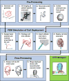
Fig. 1
Workflow for coil deployment, including three main components: pre-processing, FEM simulation, and post-processing. Device deployment results enable hemodynamic analysis.
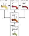
Fig. 2
Workflow for deploying overlapping flow diverters. After (1) running HiFiVS to implant the 1st FD, we (2) isolated the parent vessel and scaled it down by a distance of 1~2 FD wire diameters to fit entirely inside the 1st deployed FD. Then, we ran a second HiFiVS simulation to (3) deploy the 2nd FD in the scaled-down vessel lumen. Finally, we (4) superimposed the two intermediate deployed FD simulation results, (5) removed the scaled-down vessel and ran one or more FEM simulations to allow the 2nd FD to expand into the 1st FD.
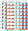
Fig. 3
FEM modeling and CFD results for coiling (coils only) and flow diversion with adjunctive coils (coils + FD). 1C–8C represents 1–8 coils with packing density from 3.7–29.6% (each coil adds 3.7%) A and B. Deployment results. Each successively deployed coil is depicted with a unique color for clarity and to help visualize changes in their configurations with deployment of successive coils. C and D. Blood streamlines. Each vessel inlet was seeded with 100 streamlines for consistency. The flow was from right to left. E and F. Velocity magnitude contours. The white gaps represent the intersection of the aneurysm mid-plane with the coils. G and H. Wall shear stress contours. They reveal zones of low WSS at the apex of the aneurysm sac as the number of coils deployed increases in both intervention strategies.
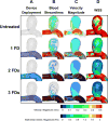
Fig. 4
FEM modeling and CFD results for a single flow diverter and overlapping flow diverters. A. FEM modeling results for 1, 2 and 3 flow diverters. Successively deployed flow diverters are colored by blue, green, and magenta. B. Blood streamline results for untreated aneurysm and treatment by 1, 2 and 3 FDs. Each vessel inlet was seeded with 100 streamlines for consistency. The flow was from right to left. C. Velocity magnitude contours on the aneurysm mid-plane D. Wall shear stress distributions.
Fig. 5
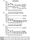
Hemodynamic quantities for coils only, FD only, and coils + FD, relative to the untreated case (with a hemodynamic baseline of 100%). A. Inflow rate. B. Aneurysm-averaged velocity. C. Aneurysm-averaged wall shear stress. Aneurysm-averaged values are volumetrically-averaged in the aneurysm sac. Each coiling scenario (1C–8C) corresponds to a packing density ranging from 3.7%–29.6%.
Fig. 6
Hemodynamic quantities (inflow rate, aneurysm-averaged velocity, and aneurysm-averaged wall shear stress) for overlapping flow diverters, relative to the untreated case. A general decrease of inflow rate, aneurysm-averaged velocity, and aneurysm-averaged wall shear stress was observed with successively deployed flow diverters, but the decrease is minimal from 2 FDs to 3 FDs.
Similar articles
- High-fidelity virtual stenting: modeling of flow diverter deployment for hemodynamic characterization of complex intracranial aneurysms.
Xiang J, Damiano RJ, Lin N, Snyder KV, Siddiqui AH, Levy EI, Meng H. Xiang J, et al. J Neurosurg. 2015 Oct;123(4):832-40. doi: 10.3171/2014.11.JNS14497. Epub 2015 Jun 19. J Neurosurg. 2015. PMID: 26090829 Free PMC article. - Hemodynamic Effect of Flow Diverter and Coils in Treatment of Large and Giant Intracranial Aneurysms.
Jing L, Zhong J, Liu J, Yang X, Paliwal N, Meng H, Wang S, Zhang Y. Jing L, et al. World Neurosurg. 2016 May;89:199-207. doi: 10.1016/j.wneu.2016.01.079. Epub 2016 Feb 4. World Neurosurg. 2016. PMID: 26852712 - Outcome prediction of intracranial aneurysm treatment by flow diverters using machine learning.
Paliwal N, Jaiswal P, Tutino VM, Shallwani H, Davies JM, Siddiqui AH, Rai R, Meng H. Paliwal N, et al. Neurosurg Focus. 2018 Nov 1;45(5):E7. doi: 10.3171/2018.8.FOCUS18332. Neurosurg Focus. 2018. PMID: 30453461 Free PMC article. - The Silk flow-diverter stent for endovascular treatment of intracranial aneurysms.
Alghamdi F, Morais R, Scillia P, Lubicz B. Alghamdi F, et al. Expert Rev Med Devices. 2015;12(6):753-62. doi: 10.1586/17434440.2015.1093413. Epub 2015 Sep 28. Expert Rev Med Devices. 2015. PMID: 26415045 Review. - Hemodynamic impact of cerebral aneurysm endovascular treatment devices: coils and flow diverters.
Goubergrits L, Schaller J, Kertzscher U, Woelken T, Ringelstein M, Spuler A. Goubergrits L, et al. Expert Rev Med Devices. 2014 Jul;11(4):361-73. doi: 10.1586/17434440.2014.925395. Expert Rev Med Devices. 2014. PMID: 24918904 Review.
Cited by
- Phantom-based experimental validation of fast virtual deployment of self-expandable stents for cerebral aneurysms.
Zhang Q, Meng Z, Zhang Y, Yao K, Liu J, Zhang Y, Jing L, Yang X, Paliwal N, Meng H, Wang S. Zhang Q, et al. Biomed Eng Online. 2016 Dec 28;15(Suppl 2):125. doi: 10.1186/s12938-016-0250-6. Biomed Eng Online. 2016. PMID: 28155680 Free PMC article. - [Finite element simulation of stent implantation and its applications in the interventional planning for hemorrhagic cardio-cerebrovascular diseases].
Wang S, Cai Y, Meng Z, Zhang X, Yang X, Dong Z. Wang S, et al. Sheng Wu Yi Xue Gong Cheng Xue Za Zhi. 2020 Dec 25;37(6):974-982. doi: 10.7507/1001-5515.202008063. Sheng Wu Yi Xue Gong Cheng Xue Za Zhi. 2020. PMID: 33369336 Free PMC article. Chinese. - Virtual stenting workflow with vessel-specific initialization and adaptive expansion for neurovascular stents and flow diverters.
Paliwal N, Yu H, Xu J, Xiang J, Siddiqui A, Yang X, Li H, Meng H. Paliwal N, et al. Comput Methods Biomech Biomed Engin. 2016 Oct;19(13):1423-1431. doi: 10.1080/10255842.2016.1149573. Epub 2016 Feb 22. Comput Methods Biomech Biomed Engin. 2016. PMID: 26899135 Free PMC article. - Modeling Flow in Cerebral Aneurysm After Coils Embolization Treatment: A Realistic Patient-Specific Porous Model Approach.
Romero Bhathal J, Chassagne F, Marsh L, Levitt MR, Geindreau C, Aliseda A. Romero Bhathal J, et al. Cardiovasc Eng Technol. 2023 Feb;14(1):115-128. doi: 10.1007/s13239-022-00639-x. Epub 2022 Jul 25. Cardiovasc Eng Technol. 2023. PMID: 35879587 Free PMC article. - Treatment Efficacy Analysis in Acute Ischemic Stroke Patients Using In Silico Modeling Based on Machine Learning: A Proof-of-Principle.
Winder A, Wilms M, Fiehler J, Forkert ND. Winder A, et al. Biomedicines. 2021 Sep 29;9(10):1357. doi: 10.3390/biomedicines9101357. Biomedicines. 2021. PMID: 34680474 Free PMC article.
References
- Appanaboyina S, Mut F, Lohner R, Putman C, Cebral J. Simulation of intracranial aneurysm stenting: Techniques and challenges. Computer Methods in Applied Mechanics and Engineering. 2009;198:3567–3582.
- Babiker MH, Chong B, Gonzalez LF, Cheema S, Frakes DH. Finite element modeling of embolic coil deployment: multifactor characterization of treatment effects on cerebral aneurysm hemodynamics. Journal of biomechanics. 2013a;46:2809–2816. - PubMed
- Babiker MH, Gonzalez LF, Albuquerque F, Collins D, Elvikis A, Zwart C, Roszelle B, Frakes DH. An in vitro study of pulsatile fluid dynamics in intracranial aneurysm models treated with embolic coils and flow diverters. IEEE transactions on bio-medical engineering. 2013g;60:1150–1159. - PubMed
- Brinjikji W, Cloft HJ, Fiorella D, Lanzino G, Kallmes DF. Estimating the proportion of intracranial aneurysms likely to be amenable to treatment with the pipeline embolization device. Journal of neurointerventional surgery. 2013;5:45–48. - PubMed
- Byrne JV, Szikora I. Flow diverters in the management of intracranial aneurysms: a review. EJMINT Orig Artic. 2012;1225000057:1–22.
Publication types
MeSH terms
Grants and funding
- R01 NS064592/NS/NINDS NIH HHS/United States
- R01 NS091075/NS/NINDS NIH HHS/United States
- UL1 TR001412/TR/NCATS NIH HHS/United States
- R01NS091075/NS/NINDS NIH HHS/United States
LinkOut - more resources
Full Text Sources
Other Literature Sources
Medical
Research Materials
Miscellaneous
