Nuclear envelope assembly defects link mitotic errors to chromothripsis - PubMed (original) (raw)
Nuclear envelope assembly defects link mitotic errors to chromothripsis
Shiwei Liu et al. Nature. 2018 Sep.
Abstract
Defects in the architecture or integrity of the nuclear envelope are associated with a variety of human diseases1. Micronuclei, one common nuclear aberration, are an origin for chromothripsis2, a catastrophic mutational process that is commonly observed in cancer3-5. Chromothripsis occurs after micronuclei spontaneously lose nuclear envelope integrity, which generates chromosome fragmentation6. Disruption of the nuclear envelope exposes DNA to the cytoplasm and initiates innate immune proinflammatory signalling7. Despite its importance, the basis of the fragility of the micronucleus nuclear envelope is not known. Here we show that micronuclei undergo defective nuclear envelope assembly. Only 'core' nuclear envelope proteins8,9 assemble efficiently on lagging chromosomes, whereas 'non-core' nuclear envelope proteins8,9, including nuclear pore complexes (NPCs), do not. Consequently, micronuclei fail to properly import key proteins that are necessary for the integrity of the nuclear envelope and genome. We show that spindle microtubules block assembly of NPCs and other non-core nuclear envelope proteins on lagging chromosomes, causing an irreversible defect in nuclear envelope assembly. Accordingly, experimental manipulations that position missegregated chromosomes away from the spindle correct defective nuclear envelope assembly, prevent spontaneous nuclear envelope disruption, and suppress DNA damage in micronuclei. Thus, during mitotic exit in metazoan cells, chromosome segregation and nuclear envelope assembly are only loosely coordinated by the timing of mitotic spindle disassembly. The absence of precise checkpoint controls may explain why errors during mitotic exit are frequent and often trigger catastrophic genome rearrangements4,5.
Conflict of interest statement
The authors declare no competing interests.
Figures
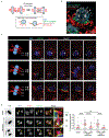
Extended Data Figure 1.. Defective nuclear envelope assembly on lagging chromosomes (or chromosome bridges) generated by multiple methods.
a, Cartoon showing the NE subdomains that transiently form around the main chromosome mass in a telophase cell, and summarizing results reported here for lagging chromosomes. DNA is shown in light blue. Lamina-associated polypeptide 2α/β (LAP2α/β). Barrier-to-autointegration factor (BAF). Lamin B receptor (LBR). The NPC is a complex containing nucleoporins (Nups), including Nup133, Nup107, ELYS, Tpr, Nup153, Nup358 and Nup62 (see Extended Data Figs 1d, 2f). b, Live-cell/ fixed cell imaging showing the recruitment pattern of core (emerin) and non-core (Nup133) proteins onto lagging chromosomes (yellow arrows) and the main chromosome mass at the indicated timepoints after anaphase onset (AO, t=0). Top: Experimental scheme. RFP-H2B-expressing RPE-1 cells were released from the nocodazole mitotic block, imaged on gridded coverslips at 2 min intervals, and then fixed and labeled for immunofluorescence (as in Extended Data Fig. 4e). Bottom: cartoons (left) and images of RPE-1 cells showing DNA (blue), emerin (red) and Nup133 (green). Each image is representative of 20 cells (from 2 technical replicates) from the indicated timepoints. Scale bars, 10 μm. Note: there is some variability between cells (~1–2 min) for the timing at which different proteins are recruited. During early-mid anaphase (2–4 min post AO), Nup133 is on kinetochores as previously described (green dots in the cartoon). ~4–6 min post AO, Nup133 begins to assemble on the chromosome periphery (enlarged image in the right most column, white arrowheads). ~6–8 min post AO, the membrane protein emerin assembles on lagging chromosome and the main chromosome mass, including the region adjacent to the central spindle (enlarged image in the right most column, orange arrowheads, microtubules are not shown). By 8–12 min post AO, emerin becomes concentrated in a recognizable “core” domain, which is also detected as a gap in Nup133 signal (enlarged image). The peripheral localization of Nup133 (e.g., 8 min) marks the “non-core” domain, cartooned in (a). About half of the NPCs of the interphase nucleus assemble in this ~ 8–10 minute period of telophase (hereafter referred to as late mitotic NPC assembly). Note that nuclear pore proteins display the most obvious “non-core” gap, whereas other non-core proteins, such as LBR, more commonly display reduced signal intensity within the core domain (Extended Data Fig. 1e, top row, RPE-1), rather than absence of signal in this region. Defective Nup133 assembly on lagging chromosomes persists throughout the mitotic exit (>15 min post AO). By ~15 min post AO, the core and non-core domains become intermingled on the main nucleus, with fragments of the core domain persisting as “pore-free” islands that slowly populated by NPCs during interphase,. c, Similar to RPE-1 cells (see b above), images of HeLa Kyoto (HeLa K) cells (representative of 30 cells, from 2 experiments) showing the “core” membrane proteins emerin (top two rows) and LAP2β (bottom two rows) first associate with the chromosome periphery (yellow arrowheads) contemporaneously with the non-core (NPC, mAb414 detects FG-containing nucleoporins.) proteins. ~2–4 min later, the core proteins extend into and then concentrate (emerin, orange arrowheads; LAP2β does not concentrate) in the core domain (red arrowheads). Cells were synchronized as in Extended Data Fig. 1e. Note in HeLa K cells, lagging chromosomes often exhibit a slight delay (~1–2 min) in the recruitment of core membrane proteins (emerin and LAP2β) as compared to the periphery of the main chromosome mass. Scale bars, 10 μm. Discussion: It is thought that the NE likely assembles from a continuous network of mitotic endoplasmic reticulum (ER). It is therefore simplest to propose that the core and non-core subdomains are also in a continuous network, but the core domain is just a region of the continuous ER network that is missing the non-core subgroup of proteins. Supporting this idea, prior work and our data (b, c above) show that the core proteins initially assemble together with the non-core proteins around the chromosome periphery and only later become enriched in the regions near the microtubules. This data suggests a model that the domain partitioning could come solely from NPC precursors and LBR (which requires ELYS for recruitment,) being preferentially retained in fenestrated ER sheets that might less readily penetrate bundled spindle microtubules (see Fig. 3a). Although we favor this model, at this point, we cannot exclude the alternative that core and non-core proteins somehow partition into separate membrane compartments. d, Quantitation of defective non-core NE protein recruitment to lagging chromosomes in different cell lines. Synchronization as in Fig. 1a (n=64, 118, 151, 124, 151, 145, 150, 69, 90, 65, 70, 60, 64, left to right, from 3 experiments for RPE-1, n=149, 110, 124, 132, from 2 experiments for HeLa K and n=44, 76, from 2 experiments for U2OS cells). e, f, Orthogonal method (1 μM NMS-P715, MPS1i) to generate lagging chromosomes shows a similar non-core NE assembly defect as observed with the nocodazole block-and-release protocol (Fig. 1a). e, Top: Experimental scheme. Bottom: Representative images of RPE-1 and HeLa K cells. Note that in RPE-1 cells and U2OS cells there is a near absence of non-core protein on lagging chromosomes, irrespective of the method to generate them. However, in HeLa K cells, the effect is slightly less penetrant. ~60% of lagging chromosomes lack detectable non-core protein recruitment, ~15% display strongly reduced levels (scored as labeled but shown in gray bar as “reduced”, see f) , and ~25% display a clear signal (Nup133), but often only covering part of the circumference of the lagging chromosome. These subtle differences are likely explained by differences in spindle organization between cell lines (see Fig. 3 and Extended Data Fig. 6, 7, 8 below). f, Quantitation of the results in different cell lines (n=56, 78 for RPE-1, from 2 experiments; n=75, 174 for HeLa K, from 3 experiments). Scale bars, 10 μm. g, h, Chromatin bridges (arrows) formed after nocodazole release or after partial depletion of the condensin SMC2, display core-only NE protein assembly. g, Images of an RPE-1 cell after release from a nocodazole block (representative of 30 DNA bridges, from 5 experiments). h, Top: Experimental scheme for generating chromosome bridges by partial SMC2 depletion. Bottom: Images of an emerin-GFP expressing RPE-1 cell. Percentage of cells with the indicated staining pattern are on the lower right (n=30, from 2 experiments). Scale bars, 10 μm. Note that the DNA bridges are uniformly depleted for non-core (LBR) proteins, with no evidence for a gradient (i.e. increased LBR away from the central spindle) as might be expected for the chromosome separation checkpoint hypothesis,. We also note that interphase chromatin bridges were previously reported to have an altered NE protein composition including reduced levels of lamin B1 and NPCs, which is consistent with our findings here.
Extended Data Figure 2.. NPC and other non-core protein assembly defect persists in interphase micronuclei in multiple cell lines.
a-c, Defective non-core NE protein recruitment to micronuclei (MN) in RPE-1 cells. a, Top: Experimental scheme. Bottom: Representative images (see b for quantification) with MN (arrows, insets for enlarged images). Red letters: core NE proteins; Green: non-core proteins. b, Quantification of the results from a. The fluorescence intensity (FI) ratio of the indicated NE proteins in intact MN (RFP-NLS positive) relative to primary nucleus (PN) at the indicated timepoints after release from nocodazole block (mean with 95% CI, n=97, 120, 106, 92, 114, 104, 113, 116, 104, 114, 121, 91, 114, 89, 113, 116, 125, left to right, from 2 experiments). Scale bars, 10 μm. c, MN/PN FI ratio of the core membrane protein LAP2β in RPE-1 cells at the indicated timepoints after release from a nocodazole block (mean with 95% CI, n=70, 49, from 2 experiments). d, Deficiency of non-core proteins persists in micronuclei in HeLa K (left) and U2OS (right). MN/PN FI ratio of the indicated NE proteins after release from a nocodazole block as in a (mean with 95% CI, n=84, 111, 90, 79, 84, 111, 90, 111, left to right for HeLa K, from 2 experiments; n= 53, 47, 45, 53, 66, 23, 64, 53, 27, 66, 54, 28, 53, 47, 46, 53, 69, 23, left to right for U2OS, from 2 experiments). e, Representative images of U2OS cells from d showing reduced assembly of B-type lamins in MN (arrows) at 90 min post nocodazole release. Scale bars, 10 μm. f, Reduced NPC assembly on MN. MN/PN FI ratio of the indicated NPC proteins in RPE-1 cells at indicated timepoints after release from nocodazole block (mean with 95% CI, n=47, 44, 49, 51, 49, 56, left to right, from 2 experiments). g, Reduced accumulation of B-type lamins but not A-type lamins on intact micronuclei. Left: Representative images of RPE-1 (left) and HeLa K (right) cells. In the enlarged merged images from the orange boxed region (HeLa K), the intensity of the lamin B1 has been scaled differently to illustrate two points. First, there is a reduction of lamin B in MN but not lamin A/C, which becomes evident when the lamin B and lamin A/C on the main nucleus are scaled to the same intensity. Second, some MN display a lamin B1 gap, as has been previously reported, (arrowheads, the lamin B1 gap formed where the lamin A/C rim is still continuous), which becomes evident when the lamin B1 intensity is scaled to a higher level. Graphs on the right: General reduction of B-type lamins in micronuclei. MN/PN FI ratio for the indicated lamins. Shown is the background-subtracted raw data for each individual micronucleus analyzed in the indicated cell lines (n=116 for RPE-1, n=111 for HeLa K, from b, d above), 5h post nocodazole release. Scale bars, 10 μm. Note that a fraction of micronuclei exhibit a reduced level of lamin A/C, which may be caused by impaired import of lamin A/C during interphase.
Extended Data Figure 3.. Micronuclei have defective nuclear import and impaired accumulation of nuclear proteins.
a, b, Defective nuclear import kinetics in newly formed MN visualized by high temporal resolution, confocal live-cell imaging. MN were generated in RPE-1 (a) or U2OS (b) cells as in Fig. 1a. a, Defective nuclear RFP-NLS import in RPE-1 cells. Left: Cartoon depicting categories of cells with differing levels of accumulation of the import reporter in MN as compared to the PN (see also in Fig. 1c for quantitation). Middle: Graphs showing nuclear import kinetics obtained from representative RPE-1 cells expressing GFP-H2B and RFP-NLS for PN (blue) and MN (red). Black lines indicate the mean values from 11 PN; shaded regions indicate standard deviation (SD). To control for photobleaching, the bleaching coefficient of the RFP-NLS signal was experimentally determined by imaging of cells during late interphase when nuclear import was presumed to be at steady state. A correction based on this bleaching coefficient obtained for 12 PN and MN pairs was then applied to the data presented here (see Methods). Right: Representative images from a time-lapse series from RPE-1 cells expressing GFP-H2B (left) and RFP-NLS (right). Time is in min. Arrows indicate a pair of PN with RFP-NLS import evident from 10 min. Yellow boxes show lagging chromosomes and the resulting MN with nuclear RFP-NLS accumulation defects (insets: enlarged images). A heat map of RFP-NLS intensity is shown in the bottom right panel (t=53 min) illustrating the strong import defect in the MN (see Supplementary Videos 1and2). b, Defective nuclear GFP-IBB import in lagging chromosomes from U2OS cells. Top: Percentage of micronuclei corresponding to the categories (a, cartoon) in U2OS cells expressing RFP-H2B and GFP-IBB (n=18 cells, from 17 experiments). Bottom: Images from a time-lapse series (boxes, lagging chromosomes and micronuclei). Scale bars, 10 μm. c, Impaired nuclear accumulation of multiple proteins in MN relative to PN. Top: Representative images of RPE-1 cells with an intact MN or a disrupted MN (arrows, MN disruption is visualized by hyper-accumulation of GFP-BAF. Both the intact and disrupted MN lack detectable accumulation of RPA2. Middle: MN/PN FI ratio of RPA2 (mean with 95% CI, n=62, 23, from 2 technical replicates). MN were generated in RPE-1 cells as in Extended Data Fig. 1e. Bottom: FI ratio of the indicated proteins in intact (RFP-NLS positive) MN from RPE-1 cells at the indicated timepoints after nocodazole release as in Extended Data Fig. 2a (mean with 95% CI, n=89, 99, 89, 98, 107, 100, 107, 100, left to right, from 3 experiments). Lysine-specific histone demethylase 1 (LSD1). Retinoblastoma protein (Rb). Scale bars, 10 μm. d, e. Live-cell/fixed cell imaging showing impaired nuclear accumulation of RPA2 and RFP-NLS in MN after mitotic exit. d, Top: Experimental scheme. Bottom: Images from wide-field time-lapse series followed by fixation and confocal imaging at the end of the experiment. The confocal images (from red and blue boxed regions) illustrate reduced accumulation of RFP-NLS and RPA2 in newly formed MN (yellow and red arrows). Time post AO (t=0 min) is shown. Scale bars, 10 μm. see e for quantification, numbers, and experimental repetitions. e, Top: MN/PN FI ratio of RPA2 and RFP-NLS in RPE-1 cells ~1h post AO (mean with 95% CI, n=211, from 2 experiments). Bottom: Defective accumulation of RPA2 and RFP-NLS are correlated (r= 0.9039, P<0.0001, two-tailed Spearman’s correlation analysis).
Extended Data Figure 4.. Proximity to spindle midzone Aurora B does not affect the NE assembly defect of lagging chromosomes; this non-core NE assembly defect persists through late telophase regardless of whether Aurora B is active.
a, Core membrane proteins (LAP2β and emerin), assemble on lagging chromosomes and chromosome bridges, independent of their position relative to the spindle midzone. Top: Images of a GFP-BAF and RFP-LAP2β-expressing RPE-1 cell show recruitment of LAP2β to lagging chromosome (arrow). Bottom: Images of an emerin-GFP-expressing RPE-1 cell show recruitment of emerin to a chromosome bridge (arrowhead). Both LAP2β and emerin can assemble near the concentration of Aurora B (white, in merged images) at the spindle midzone (representative of 30 cells, from 2 experiments). Cells synchronized as in Fig. 1a. Scale bars, 10 μm. b, c, Live-cell/ fixed cell imaging showing that loss of H3S10 phosphorylation in late telophase does not enable non-core NE assembly onto lagging chromosomes. b, Top: Experimental scheme. Bottom: Representative images of RPE-1 cells. Scale bars, 10 μm. c, FI measurements from the main chromosome mass (PN) and lagging chromosome (MN) showing loss of H3S10 phosphorylation relative to the recruitment of NPC proteins in the same cell at the indicated timepoints. Top: Phospho-H3S10 with a mouse monoclonal anti-pH3S10 antibody (mean with 95% CI, n=31, 46, 34, 27, 26, 28, 34, 26 each timepoint for MN and PN mouse-pH3S10, from 2 experiments; n=31, 46, 34, 27, 26, 28, 34, 26 each timepoint for MN and PN Nup133, from 2 experiments). Bottom: rabbit polyclonal anti-pH3S10 antibody (mean with 95% CI, n=27, 20, 33, 29, 22, 30, 22, 32, 31, 28 each timepoint for MN and PN rabbit-pH3S10, from 2 experiments; n=30, 49, 28, 32, 30, 19, 32, 32, 27 each timepoint for MN and PN Nup107, from 2 experiments). Zero timepoint measurements for both MN and PN were from metaphase chromosomes. The specificity of both anti-pH3S10 antibodies was confirmed by the near-complete loss of labeling after treatment of nocodazole-arrested mitotic cells with 50 μM ZM447439 (not shown). Note that Nup133 starts to assemble on the main chromosomes (~4–6 min post AO, also see Extended Data Fig. 5b) with readily detected H3S10 phosphorylation. d, MKLP2 knockdown, disrupting the transport of Aurora B to the spindle midzone, fails to restore non-core (LBR) NE assembly to lagging chromosomes (arrows). Synchronization as in Fig. 1a. Left: Representative images of control or MKLP2-depleted RPE-1 cells. Middle: MN/PN FI ratio of LBR. For MN in MKLP2 depleted cells, only cells lacking detectable midzone Aurora B were quantified (mean with 95% CI, n=118, 105, from 3 experiments). NS: Not significant (P=0.8147), two-tailed Mann-Whitney test. Right: Western blot showing MKLP2 knockdown in RPE-1 cells (2 experiments, for gel source data, see Supplementary Fig. 1). Scale bars, 10 μm. e, Scheme of the live-cell/ fixed cell imaging protocol. RFP-H2B-expressing RPE-1 cells were plated on gridded dishes to identify cells of interest. Cells were imaged at 2 min intervals during the experiments. Representative images of two live cells (red and blue boxes) upon (left) or after (right, prior to fixation) ZM447439 addition. f, Consistent with prior studies,,, Aurora B inhibition (ZM447439, 5 μM or 50 μM) rapidly (3 min) inactivates the kinase (mean with 95% CI, n=48, 17, 19, from 2 technical replicates). **** P < 0.0001, two-tailed Mann-Whitney test. Active Aurora B was assessed by the FI ratio of phospho-Aurora B (pT232) to total Aurora B in the midbody of telophase cells 3 min after ZM or DMSO addition. RPE-1 cells were synchronized as in Fig. 1a. g, Ten-fold higher (50 μM) Aurora B inhibitor concentration gives similar results as obtained with 5 μM inhibitor treatment (Fig. 2a), confirming that early Aurora B inhibition (2 min before-2 min after AO) but not late (6–12 min post AO) partially restores non-core protein (Nup133) recruitment to lagging chromosomes. Note that non-core NE is only partially restored on a fraction of lagging chromosomes even with the high dose of inhibitor (early 50 μM ZM447439) even though this treatment led to a uniform loss of phospho-H3S10 on all chromosomes after anaphase entry (not shown). Therefore, the persistent NE assembly defect on lagging chromosomes after Aurora B inhibition cannot be explained by residual phospho-H3S10. Instead, the partial effect is explained by the effects of Aurora B inhibition on the local organization of microtubules (see Extended Data Fig. 8d). Shown is the MN/PN FI ratio of Nup133 at the indicated time intervals and drug doses (mean with 95% CI, n=33, 37, 37, 52, 37, left to right, from 2 experiments). Experiments performed as in Fig. 2a in RPE-1 cells. For simplicity, timepoints corresponding to ± 2 min post AO were grouped as “early” treatment, whereas timepoints corresponding to 6–12 min post AO were grouped as “late” treatment. *** P=0.0001 (DMSO and early 5 μM ZM), ***P=0.0003 (early 5 μM ZM and late 5 μM ZM), **** P < 0.0001, NS: not significant (P=0.494), two-tailed Mann-Whitney test.
Extended Data Figure 5.. Rather than persistent condensins, the irreversible NE assembly defect of lagging chromosomes may be caused by enclosure in an NPC-deficient NE.
a-c, Loss of condensin (SMC2) is not required for non-core/NPC assembly. a, Representative images of control and SMC2-depleted RPE-1 cells showing that loss of SMC2 does not restore non-core assembly on lagging chromosomes (see b, c for quantification). Scale bar, 10 μm. b, Top: Experimental scheme of live-cell/ fixed cell imaging. Middle and bottom: FI of Nup133 and SMC2 on the main chromosome mass (PN) and lagging chromosomes (MN) at timepoints after AO in RPE-1 cells (mean with 95% CI, n=52, 37, 35, 44, 35, 36, 32, 46, 41 each timpoint for MN SMC2, from 3 experiments; n=52, 37, 47, 55, 40, 48, 38, 46, 41 each timepoint for PN SMC2, from 3 experiments; n=31, 28, 37, 22, 23, 25, 26, 28, 34 each timepoint for MN and PN Nup133, from 2 experiments). Zero timepoint measurements for both MN and PN were from metaphase chromosomes. Dashed lines indicate timepoints, demonstrating that Nup133 can assemble on the main chromosome mass when condensins are present at ~70% of their maximum levels in metaphase. Note that for MN (~10 min post AO), the decline in SMC2 levels is slower than on the PN, presumably because of a requirement for nuclear transport for complete chromosome decondensation. c, Top: SMC2 levels on PN and MN during telophase in control and SMC2-depleted cells (mean with 95% CI, n=58, 58, 75, 75, left to right, from 2 experiments). **** P < 0.0001, two-tailed Mann-Whitney test. Middle: MN/PN FI ratio of mAb414 to detect nucleoporins. For MN in SMC2 depleted cells, only cells with no detectable SMC2 were quantified for mAb414 (mean with 95% CI, n=35, 45, from 2 experiments). NS: Not significant (P=0.9251), two-tailed Mann-Whitney test. Bottom: Western blot showing SMC2 knockdown in RPE-1 cells (2 experiments, for gel source data, see Supplementary Fig. 1). d, e, ESCRT-III recruitment to lagging chromosomes. d, Normal kinetics for the association and dissociation of ESCRT-III (CHMP4B-GFP) on lagging chromosomes during NE reformation. Lagging chromosomes were induced in HeLa K cells expressing CHMP4B-GFP (green) and RFP-H2B (red) by the nocodazole block-and-release protocol as in Fig. 1a and imaged at 1 min intervals on a confocal microscope (Supplementary Video 3). Left: A representative cell showing the CHMP4B residence time on lagging chromosome (referred as MN) as compared to the residence time on the PN. Right: Enlarged images of boxed regions showing lagging chromosome (white arrowheads). The duration of CHMP4B association with the PN or MN is shown by the colored bars above the time-lapse series. Similar results were obtained for chromosome bridges (not shown). Note that prior work on normal NE assembly suggests that the timely dissociation of CHMP4B is a marker for successful NE sealing and that delayed CHMP4B dissociation is a marker for defective NE sealing. The normal ESCRT-III kinetics on lagging chromosomes or chromosome bridges therefore suggests significant NE membrane sealing on these structures (representative of 10 cells, from 6 experiments). ESCRT-III was not detected on newly formed micronuclei after mitotic exit (not shown). We note that ESCRT-III was previously reported to associate with interphase MN, which we also observe, but only on disrupted MN (not shown). We also note that the previously described enrichment of ESCRT-III in the core domain of the main chromosome mass is less apparent after nocodazole release (shown here) than is observed when lagging chromosomes are generated by MPS1i treatment (see Extended Data Fig. 9b). Scale bars, 10 μm. e, ESCRT-III (CHMP4B, CHMP2A and IST1) is recruited to lagging chromosomes in telophase RPE-1 cells. Cells were labeled to detect the indicated proteins synchronized from nocodazole release as in Fig.1a. Graph showing percentage of lagging chromosomes that were positive for the indicated proteins in early telophase cell (when the main chromosome mass is positive for ESCRT III, PN+) and late telophase cell (when ESCRT III is no longer detected on the main chromosome mass, PN-) (n=44, 78, 45, 31, 67, 37, each category, from 2 experiments). f, Near-continuous assembly of core membrane protein around the lagging chromosome. Images of 3D-SIM (left) and Imaris surface renderings (right) of an emerin-GFP-expressing RPE-1 cell. Enlarged images show lagging chromosomes (yellow box) and PN (white box): DNA (blue), emerin (red), Nup133 (green) (representative of 22 cells, from 2 technical replicates). g, Correlative light and electron microscopy (CLEM) showing double-membranous NE (enlarged images in middle panels, cross sections) but reduced NPCs on intact (RFP-NLS positive) and newly disrupted MN (RPF-NLS negative, red arrows). An RPE-1 cell was fixed <20 min after spontaneous disruption of one of MN. Left, top: DIC and fluorescence images immediately after loss of RFP-NLS signal in one of the two MN present in the cell. Right, top: 70-nm thin section selected from the full series of the cell. Double-membranous NE is present on the PN as well as on the disrupted (red arrow) and intact MN. Middle-row panels depict NE at higher magnification. NPCs are prominent in the tangential view (bottom-row panels) of primary nucleus (yellow arrows) but not on NLS-positive MN (blue arrows). No NPC is present on the disrupted RPF-NLS negative MN. Representative of 4 cells with 3 intact and 4 newly disrupted MN, from 3 experiments (see details in the Methods).
Extended Data Figure 6.. Microtubule disruption restores non-core NE assembly to lagging chromosomes only if it occurs early in anaphse.
a, Aurora B inhibition (5 μM ZM447439) reduces spindle microtubule bundling and microtubule mass. Left: Representative images of RPE-1 cells (n=20, from 2 technical replicates). Right: Linescan profiles of the FI for α-tubulin (red) along the white dashed lines (see the enlarged images from the boxed region). Scale bars, 10 μm. b, c, Parallel effects of nocodazole and Aurora B inhibitor treatment (see Fig. 2a) on non-core NE assembly. Live-cell/ fixed cell imaging as in Fig. 2a showing that nocodazole-mediated microtubule depolymerization only allows non-core NE assembly if it occurs early in anaphase. Labeling to detect α-tubulin and LBR is in b; labeling to detect α-tubulin and Nup133 is in c. Left (b, c): Representative images of RPE-1 cells exposed to DMSO or nocodazole at the indicated times post AO (fixation and labeling of cells was performed 12 min after DMSO or nocodazole addition). Yellow arrows (b, c) indicate lagging chromosomes; White arrowhead (enlarged images in c) shows that even on a lagging chromosome where Nup133 (green) has largely been restored after nocodazole treatment, the region of this chromosome that remains in contact with residual microtubules (red) is depleted for Nup133. Right, (b, c): Experimental scheme is shown on the top (see Extended Data Fig. 4e) and quantification is shown on the bottom. “12+” includes cells that exposed to nocodazole 12–16 min post AO. (b) MN/PN FI ratio for LBR (mean with 95% CI, n=64, 62, 54, 44, 63, 69 each timepoint, from 3 experiments); (c) the fraction of the lagging chromosome circumference with Nup133 (mean with 95% CI, n=33, 29, 22, 21, 24, 64 each timepoint, from 2 experiments). **** P < 0.0001, two-tailed Mann-Whitney test. Scale bars, 10 μm. d, Independence for the formation of the non-core gap from the normal spatial distribution of Aurora B. Images showing that a non-core protein (Nup133) is excluded from the central spindle region (white arrowheads) on the chromosome mass in HeLa K cells expressing Aurora B-GFP (white, in merged images, representative of 30 cells, from 2 technical replicates). Synchronization as in Extended Data Fig. 1e. Nup133 assembly occurred normally on the periphery of the main chromosome mass, away from the spindle, whether Aurora B localized to the central spindle or was forced to remain near the chromosome mass (MKLP2 RNAi). Scale bars, 10 μm.
Extended Data Figure 7.. KIF4A knockdown partially restores non-core NE assembly to lagging chromosomes even when they have maximal (metaphase) levels of H3S10 phosphorylation.
a, Consistent with previous studies, KIF4A knockdown largely preserves the redistribution of Aurora B from centromeres to the central spindle (arrowheads) early in anaphase. Synchronization as in Fig. 1a. Left: Images from time-lapse series are shown from control (representative of 29 cells, from 2 experiments) or KIF4A-depleted (representative of 27 cells, from 3 experiments) HeLa K cells expressing Aurora B-GFP (green) and RFP-H2B (red). Time is shown in min (t=0, AO). Right: Western blots showing depletion of KIF4A protein by siRNA in RPE-1 (top, 3 experiments) and HeLa K (bottom, 3 experiments) cells (also related to Fig. 3b, c, for gel source data, see Supplementary Fig. 1). Scale bar, 10 μm. b, Restoration of LBR to some lagging chromosomes after KIF4A depletion (RPE-1 cells). Synchronization as in Fig. 1a. Left: Representative images: DNA (blue), α-tubulin (red) and LBR (green). Right: MN/PN LBR FI ratio (mean with 95% CI, n=105, 119, from 3 experiments). **** P < 0.0001, two-tailed Mann-Whitney test. Scale bars, 10 μm. Note that the restoration of LBR is often continuous around MN with partially-restored MN/PN FI ratio (see also Fig. 2a after Aurora B inhibition), whereas the NPC assembly is commonly restored discontinuously after KIF4A depletion (see Fig. 3b, c) or Aurora B inhibition (see Extended Data Fig. 8d). This is consistent with different localization patterns of LBR and NPC in the core domain on the main chromosome mass (Extended Data Fig. 1b, c, e), which may arise from their different mobilities within the NE. **c,** Live-cell imaging confirming the partial restoration of an NPC protein (Nup107) to lagging chromosomes in HeLa K cells expressing GFP-Nup107 (green) and RFP-H2B (red) after KIF4A knockdown. Synchronization as in Fig. 1a. Images from a confocal time-lapse series are shown with arrows indicating GFP-Nup107 protein recruited to lagging chromosomes (representative of 6 cells, from 3 experiments). Time is shown in min. Scale bar, 10 μm. **d,** Unlike KIF4A knockdown, disruption of Aurora B spindle midzone localization by MKPL2 knockdown fails to restore the recruitment of Nup133 to lagging chromosomes. Synchronization as in Fig. 1a. Graph showing quantification of the results (mean with 95% CI, n=131, 136, 85, from 2 experiments). **** P < 0.0001, NS: Not significant (P=0.0616), two-tailed Mann-Whitney test. **e,** H3S10 phosphorylation does not block NPC/non-core NE assembly. Left: Representative images of KIF4A-depleted HeLa K cells showing restoration of non-core (Nup107) assembly onto lagging chromosomes with high level of H3S10 phosphorylation (red arrowhead, enlarged images of the blue boxed region). Note that the level of phospho-H3S10 is similar between the lagging chromosomes with (red arrowhead) or without (white arrowhead) Nup107 recruitment. To illustrate the relative difference in pH3S10 levels between PN and MN, pH3S10 has been scaled differently in the pH3S10 channel and the merged channel. Cells were synchronized as in Extended Data Fig. 1e. Scale bar, 10 μm. Middle: Linescan profile of the indicated proteins along the dashed line in the merged image on the left. Right: FI of phospho-H3S10 on MN and the corresponding PN (mean with 95% CI, n=24, 25, 25, 25, 24, from 2 technical replicates). In MN that have recruited Nup107 (MN/PN FI ratio >0.4), the H3S10 phosphorylation level is comparable to metaphase chromosomes. *** P =0.0009, **** P < 0.0001, NS: Not significant (P=0.0709, P=0.6699, left to right), two-tailed Mann-Whitney test.
Extended Data Figure 8.. Partitioning of the NE into core and non-core subdomains depends on the local organization of spindle microtubules.
a-c. 3D-SIM showing exclusion of non-core NE assembly from the region of the lagging chromosome adjacent to CHIMP4B marked microtubules (MTs). a. Scheme summarizing the SIM results after KIF4A knockdown. The ESCRT-III complex is recruited to small membrane holes at the sites where spindle microtubules intersect the reforming NE where it is thought to be required for normal NE sealing. Therefore, we used ESCRT-III (CHMP4B) labeling to identify the NE region on the lagging chromosome that is intersected by microtubules for the SIM experiments. b, Imaris surface three-dimensional renderings from SIM images (from c, below) showing recruitment of Nup133 (white) to the region of a lagging chromosome depleted of CHMP4B (green) and microtubules (red) from a KIF4A-depleted HeLa K cell (representative of 4 lagging chromosomes, from 2 experiments). c, SIM images showing that similar to what occurs on the main chromosome masses during normal NE assembly, NPCs (Nup133) are recruited to regions of the lagging chromosome lacking CHMP4-decorated microtubules. Left: A cartoon depicting the entire lagging chromosome visualized from a KIF4A-depleted anaphase/telophase cell (microtubules in red, DNA in blue, z focal planes as indicated). Right: Serial sections from a SIM z-stack of an anaphase/telophase HeLa K cell expressing CHMP4B-GFP (green) labeled for microtubules (red), Nup133 (white) and DNA (blue) after KIF4A depletion. These results are consistent with the idea that microtubules inhibit non-core NE assembly. d, KIF4A knockdown (Fig. 3b, c, Extended Data Fig. 7b–d) and early anaphase Aurora B inhibition have a similar effect on NPCs/non-core NE assembly to lagging chromosomes. Experiments performed as in Fig. 2a in RPE-1 cells. Left panel images: left column: Representative timelapse images of cells upon ZM447439 or DMSO addition (live, 0 or 6 min post AO); right five columns: Representative images of the same cells after fixation and labeling (12 min post treatment). For the cell exposed to ZM447439 at anaphase onset (middle row), one of the two lagging chromosomes exhibits a small-scale separation of core (white arrowhead, emerin) and non-core (white arrow, Nup133) NE domains. Scale bar, 10 μm. Right: Quantification of the results (mean with 95% CI, n=64, 72, 43, 72, 34, from 2 experiments). **** P < 0.0001, NS: Not significant (P=0.6932), two-tailed Mann-Whitney test.
Extended Data Figure 9.. Characterization of peripherally localized missegregated chromosomes and the resulting MN: microtubule proximity, nuclear import, and chromosome number.
a, Restored assembly of Nup133 on micronuclei derived from peripheral chromosomes as compared to central spindle lagging chromosomes in HeLa K cells. Left: Quantification of the fraction of the lagging chromosome circumference with Nup133 (mean with 95% CI, n=32, 40, from 2 experiments). **** P < 0.0001, two-tailed Mann-Whitney test. Right: Western blots showing depletion of TTL protein by siRNA in HeLa K cells (3 experiments, for gel source data, see Supplementary Fig. 1). b, Fewer microtubules associated with peripheral missegregated chromosomes (red arrow) as compared to MN from central missegregated chromosomes (yellow arrow). Synchronization as in Fig. 4a. Representative images of RPE-1 cells after glutaraldehyde fixation (representative of 30 for central or peripheral missegregated chromosome, from 2 technical replicates). Scale bars, 10 μm. Note the sparse microtubule density near the peripheral chromosome (bottom images) that, in 30 cells, is never associated with more than 3 CHMP4B foci. c-e, Normal nuclear import and DNA replication in MN from peripherally missegregated chromosomes (red arrows) as compared to MN from central missegregated chromosomes (yellow arrows). c, Top: Scheme of the experiment. RPE-1 cells were treated with p53 siRNA to facilitate cell-cycle progression. After mitotic exit, micronucleated cells were imaged at 20 min intervals. Bottom: Images of fixed and labeled RPE-1 cells, 4h post the RO release at the end of the live-cell experiment. Scale bars, 10 μm. See Fig. 4d for quantification of this experiment. d, MN/PN FI ratio for lamin B1 in RPE-1 cells, 4h post the RO release (mean with 95% CI, n=60, 32, from 2 experiments). **** P < 0.0001, two-tailed Mann-Whitney test. e, Restoration of DNA replication (EdU incorporation, shown as the MN/PN FI ratio) in MN from peripheral chromosomes in RPE-1 (left) and HeLa K (right) cells, 16~18h post the RO release (mean with 95% CI, n=81, 60, from 5 experiments for RPE-1; n=55, 86, from 2 experiments for HeLa K). Note that in RPE-1 cells, consistent with prior results, high dose of MPS1 inhibition causes a fraction of cells to delay in cell cycle progression. Therefore, we restricted the analysis to cells that progressed into the S-phase of the cell cycle as evidenced by EdU labeling of the primary nucleus. ** P < 0.0067, **** P < 0.0001, two-tailed Mann-Whitney test. f, MN derived from peripheral chromosomes were larger (DAPI area, top) and more decondensed (the density of DAPI FI, bottom) than MN from central chromosomes. Shown are data from RPE-1 (left) and HeLa K (right) cells (mean with 95% CI, n=145, 112, from 3 experiments for DAPI area for RPE-1, n=145, 112, from 3 experiments for DAPI FI for RPE-1; n=66, 21, from 2 experiments for DAPI area for HeLa K, n=88, 58, from 3 experiments for DAPI FI for HeLa K). **** P < 0.0001, two-tailed Welch’s t test for DAPI FI, two-tailed Mann-Whitney test for DAPI area. Note: The extensive decondensation of MN from peripheral missegregated chromosomes may be a consequence of their initiation of nuclear import slightly earlier than the assembling main daughter nuclei (Fig. 4c) as well as their difference in the ratio of surface area to volume. g, h, Micronuclear chromosome number does not influence non-core NE assembly. Comparison of chromosome number in MN from central chromosomes and peripheral chromosomes. g, Confocal images of RPE-1 cells labeled for CENP-A (a marker for centromere, arrowheads), Nup133 and DNA. Yellow arrows; central chromosomes; red arrows: peripheral chromosomes. Synchronization as in Fig. 4a. Scale bars, 10 μm. See h for quantification. h, Top: Distribution of chromosome number (CENP-A foci) in central (blue) and peripheral (red) MN. Data from RPE-1 (left) and HeLa K (right) cells are shown. Bottom: The fraction of the lagging chromosome circumference with Nup133 is shown for MN with the indicated chromosome number in RPE-1 (left) and HeLa K (right) cells (mean ± SD, n=40, 111, 20, 9, 3 each category for central chromosomes, n=0, 6, 71, 0, 11 for peripheral chromosomes, from 2 experiments for RPE-1; mean ± SD, n=2, 35, 14, 2, 0 each category for central chromosomes, n=0, 8, 6, 2, 0 for peripheral chromosomes, from 2 experiments for HeLa K). Although MN from peripheral chromosomes generally contain a higher number of chromosomes than MN from central chromosomes, non-core assembly is inhibited on MN from central chromosomes irrespective of their chromosome number. Furthermore, non-core NE assembly is significantly restored on MN from peripheral chromosomes, again irrespective of chromosome number (consistent with Fig. 4b, c).
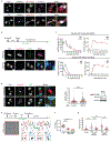
Extended Data Figure 10.. Peripheral localization of lagging chromosomes reduces MN NE disruption and DNA damage; actin-dependent peripheral MN disruption in RPE-1 cells.
a, Peripheral localization of lagging chromosomes reduces MN disruption and DNA damage. Representative images of HeLa K cells (C-MN from central chromosomes; P-MN from peripheral chromosomes). See Fig. 4e for quantification of the results. Scale bars, 5 μm. b, Detection of MN disruption by GFP-BAF accumulation yields similar results as in panel a for NE disruption detection by the loss of RFP-NLS. Representative images from a live-cell/ fixed cell imaging experiment (as in Fig. 4e) from HeLa K cells expressing GFP-BAF. Central MN (C-MN) show NE disruption detected by hyper-accumulation of GFP-BAF (top) whereas peripheral MN (P-MN) show infrequent disruption (bottom). NE disruption of central MN is accompanied by the acquisition of DNA damage (γH2AX, see Fig. 4e). At the end of 16–18h live imaging, cells were fixed and stained for γH2AX and lamin B1. See Fig. 4e for quantification of the results. Scale bars, 5 μm. c, In RPE-1 cells, peripheral MN undergo actin-dependent NE disruption. Top: Experimental scheme. Chromosome missegregation was induced in RPE-1 cells expressing RFP-H2B and GFP-BAF (or GFP-H2B and RFP-NLS) as in Extended Data Fig. 9c. ~1h post mitotic exit, cells were treated with DMSO or a low dose (150 nM) of the actin assembly inhibitor latrunculin A (LatA) and imaged for 16–18h. See discussion below for the rationale. Bottom: Shown is the percentage of peripheral or central MN that underwent NE disruption (hyper-accumulation of GFP-BAF, from 4 experiments for both DMSO and LatA) or that displayed DNA damage (FI of γH2AX in MN > 3 SD of the background γH2AX in PN, from 6 experiments for DMSO and 3 experiments for LatA). NS: Not significant (P=0.0948), ** P=0.0044, **** P < 0.0001, two-tailed Fisher’s exact test [For NE disruption: n=258 for central MN (DMSO), n=176 for peripheral MN (DMSO), n=173 for central MN (LatA), n=125 for peripheral MN (LatA); for DNA damage: n=306 for central MN (DMSO), n=182 for peripheral MN (DMSO), n=128 for central MN (LatA), n=73 for peripheral MN (LatA)]. d, Peripheral MN develop discontinuities in the lamin B1 nuclear rim. Left: Representative images of RPE-1 cells ~18h post mitotic exit, as in Extended Data Fig. 9c. Yellow boxes indicate C-MN (yellow arrowheads) that have reduced levels of lamin B1. Right: Quantification of the results (mean with 95% CI, n=61, 28, 38, 18, left to right, from 2 experiments). **** P < 0.0001, two-tailed Welch’s t test for DMSO, two-tailed Mann-Whitney test for LatA. Red boxes indicate peripheral MN, one of which displays a prominent lamin B1 rim discontinuity. Red arrowhead in the enlarged image shows an NE herniation on a peripheral MN. Scale bars, 10 μm. Discussion: Consistent with prior work, MN from lagging chromosomes undergo spontaneous disruption in a manner that is independent of actin. By contrast, it was previously shown that the transient disruption of primary nuclei, as occurs during confined cell migration, is mediated by actomyosin contractile forces. In our experiments, we confirm that MN from central lagging chromosomes undergo disruption in a manner that is independent from actin (above). However, we noted a difference between RPE-1 and HeLa K cells in the behavior of MN from peripheral chromosomes. Although NE assembly appeared to be significantly restored in both HeLa K and RPE-1 cells, peripheral MN in RPE-1 cells underwent significant residual disruption (note that there is nevertheless a statistically significant reduction of the NE disruption frequency when comparing P-MN and C-MN in RPE-1 cells). We hypothesized that in the highly motile RPE-1 cells, large peripheral MN might more likely undergo actin-dependent NE breakage, essentially becoming more similar to the transient NE disruption of primary nuclei,. The above data (c) after Lat-A treatment in RPE-1 cells confirm that peripheral MN do undergo actin-dependent breakage. Furthermore, we show that peripheral MN in RPE-1 cells have lamin B1 gaps (d, red arrowhead). One possible mechanism that could generate these gaps could be residual contact between peripheral missegregated chromosomes with astral microtubules (see Extended Data Fig. 9b). Additionally, peripheral MN are more decondensed, and have larger NE surface area which may dilute lamins. The increased breakage of peripheral MN in RPE-1 cells relative to HeLa K cells may be due to higher contractile forces in RPE-1 cells.
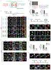
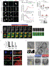
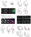
Figure 1.. Defective NE assembly on lagging chromosomes.
a. Non-core NE assembly defect on lagging chromosomes. Top: Experimental scheme. Bottom: Images of RPE-1 cells with lagging chromosomes (arrows, 3 experiments). Red: core NE proteins; Green: non-core proteins. b, c, Impaired nuclear import in micronuclei. b, Kymograph of RPE-1 cell (boxed region of top image) shows impaired import of RFP fused to a nuclear localization signal (RFP-NLS) in the newly formed micronuclei (arrowheads). Synchronization as in a (t=0 is anaphase onset, AO). Bottom: Merged image. Representative images of 9 cells, category “B” next panel. c, Top: Cartoon summarizing patterns of import to micronuclei (from b, see Extended Data Fig. 3a for representative quantification of import defects). Bottom: Percentage of micronuclei corresponding to the categories above (n=24, from 11 experiments for RPE-1, n=17, from 9 experiments for U2OS). Scale bars, 10 μm.
Figure 2.. Irreversibility of the NE assembly defect on lagging chromosomes.
a, Aurora B inhibition after late-anaphase fails to restore non-core (LBR) assembly to lagging chromosomes (arrows). Left column: Cells at the time of ZM447439 or DMSO addition (min post AO). Right columns: Cells labeled for DNA (blue), phospho-T232 Aurora B (red) and LBR (green). In controls, lagging chromosome fail to recruit LBR even if they are located (white arrowhead) far from active Aurora B (pT232). Scale bars, 10 μm. Right, top: Experimental scheme. Right, bottom: MN/PN (primary nucleus) FI ratio for LBR in cells exposed to ZM at the indicated times (mean with 95% CI, n=40, 29, 31, 31, 43, 43, 34 each timepoint, from 5 experiments. For brevity, lagging chromosomes are designated as “MN”). **** P < 0.0001, NS: P=0.0816, two-tailed Mann-Whitney test. b, CLEM showing synchronous NE formation on all chromosomes. Top left: Time course of furrow ingression in RPE-1 cells with lagging chromosomes (black line: mean, grey lines: ±1 SD). Red and blue discs indicate stages of the 10 cells analyzed by CLEM: No NE is detected by CLEM during earlier stages of cytokinetic furrowing (red); at later stages (blue), double-membranous NE is present at both PN and MN. Perinuclear space (red brackets) is wider around MN. NPCs (arrows) are present only on PN. LM images: DNA in greyscale, kinetochores (CenpA-GFP) and centrosomes (centrin1-GFP) in red. Scale bars, 0.5 μm.
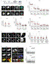
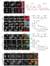
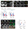
Figure 3.. Spindle microtubules block non-core NE assembly independent of Aurora B.
a, Microtubule stabilization by paclitaxel (PTX) inhibits non-core invasion of core domain. Left: Images of RPE-1 cells after drug treatment(s): Enlarged images from the boxed regions show the non-core (Nup133) gap on the main chromosome mass (red arrowheads). Right, top: Experimental scheme. Right, bottom: Quantification of the results (mean with 95% CI, n=40, 47, 41, 61, 40, 47, 41, 61, left to right, from 2 experiments). **** P < 0.0001, NS: P=0.2974, 0.9837, 0.2473, 0.3374 (left to right), two-tailed Mann-Whitney test. b, c, Small-scale core/non-core domain separation on lagging chromosomes after KIF4A depletion. b, Images of Aurora B-GFP-expressing HeLa K cells (2 technical replicates). Merged and enlarged image: Emerin (red, white arrowheads), Nup133 (green, white arrows). Synchronization as in Extended Data Fig. 1e. c, The fraction of lagging chromosome circumference covered with Nup133 in HeLa K cells (cartoon shown in left; mean with 95% CI, n=90, 52, 81, from 2 experiments). **** P < 0.0001, two-tailed Mann-Whitney test. Scale bars, 10 μm.
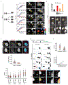
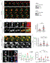
Figure 4.. Peripheral localization of missegregated chromosomes corrects defects of micronuclei.
a, Experimental scheme to generate missegregated chromosomes positioned within or away from the spindle (microtubules: red; non-core NE: green). b, c, Non-core NE assembles on peripheral chromosomes but not central chromosomes. b, Top: Images of RPE-1 cells with central (yellow arrows) and peripheral (red arrows) chromosomes labeled with core (red) or non-core (green) proteins. Bottom: Quantification as in Fig. 3c [mean with 95% CI, n=83, 67 (left), n=122, 58 (right), from 2 experiments each]. **** P < 0.0001, two-tailed Mann-Whitney test. c, Similar result as in b from live-cell imaging of a HeLa K cell expressing RFP-H2B (red) and GFP-Nup107 (green) (Supplementary Video 4, representative of 15 cells). d, e, Functional restoration of MN from peripheral chromosomes. d, FI ratios for the indicated proteins, comparing MN from peripheral with central chromosomes (RPE-1 cells, scheme as in a). **** P < 0.0001, two-tailed Mann-Whitney test (mean with 95% CI, n=130, 97, 145, 112, 52, 47, 64, 48, 64, 47, 49, 45, 49, 45, left to right, from 2 experiments for the indicated proteins). e, Top: Experimental scheme. Bottom: Graphs of the results (HeLa K cells). Left: NE integrity monitored by loss of NLS-RFP (5 experiments). Middle: NE integrity monitored by hyper-accumulation of GFP-BAF (3 experiments). Right: DNA damage (3 experiments). ** P=0.0084, **** P < 0.0001, two-tailed Fisher’s exact Test. Note: Only a fraction of ruptured MN acquire DNA damage. Scale bars, 5 μm.
Comment in
- Rotten to the Core: Why Micronuclei Rupture.
Lusk CP, King MC. Lusk CP, et al. Dev Cell. 2018 Nov 5;47(3):265-266. doi: 10.1016/j.devcel.2018.10.023. Dev Cell. 2018. PMID: 30399332
Similar articles
- A matter of wrapper: Defects in the nuclear envelope of lagging and bridging chromatin threatens genome integrity.
Rodriguez-Muñoz M, Anglada T, Genescà A. Rodriguez-Muñoz M, et al. Semin Cell Dev Biol. 2022 Mar;123:124-130. doi: 10.1016/j.semcdb.2021.03.004. Epub 2021 Mar 21. Semin Cell Dev Biol. 2022. PMID: 33757694 Review. - The coordination of nuclear envelope assembly and chromosome segregation in metazoans.
Liu S, Pellman D. Liu S, et al. Nucleus. 2020 Dec;11(1):35-52. doi: 10.1080/19491034.2020.1742064. Nucleus. 2020. PMID: 32208955 Free PMC article. Review. - cGAS surveillance of micronuclei links genome instability to innate immunity.
Mackenzie KJ, Carroll P, Martin CA, Murina O, Fluteau A, Simpson DJ, Olova N, Sutcliffe H, Rainger JK, Leitch A, Osborn RT, Wheeler AP, Nowotny M, Gilbert N, Chandra T, Reijns MAM, Jackson AP. Mackenzie KJ, et al. Nature. 2017 Aug 24;548(7668):461-465. doi: 10.1038/nature23449. Epub 2017 Jul 24. Nature. 2017. PMID: 28738408 Free PMC article. - Small but mighty: the causes and consequences of micronucleus rupture.
Kwon M, Leibowitz ML, Lee JH. Kwon M, et al. Exp Mol Med. 2020 Nov;52(11):1777-1786. doi: 10.1038/s12276-020-00529-z. Epub 2020 Nov 24. Exp Mol Med. 2020. PMID: 33230251 Free PMC article. Review. - Chromosome length and gene density contribute to micronuclear membrane stability.
Mammel AE, Huang HZ, Gunn AL, Choo E, Hatch EM. Mammel AE, et al. Life Sci Alliance. 2021 Nov 17;5(2):e202101210. doi: 10.26508/lsa.202101210. Print 2022 Feb. Life Sci Alliance. 2021. PMID: 34789512 Free PMC article.
Cited by
- Preserving Genome Integrity: Unveiling the Roles of ESCRT Machinery.
La Torre M, Burla R, Saggio I. La Torre M, et al. Cells. 2024 Aug 5;13(15):1307. doi: 10.3390/cells13151307. Cells. 2024. PMID: 39120335 Free PMC article. Review. - Aneuploid senescent cells activate NF-κB to promote their immune clearance by NK cells.
Wang RW, Viganò S, Ben-David U, Amon A, Santaguida S. Wang RW, et al. EMBO Rep. 2021 Aug 4;22(8):e52032. doi: 10.15252/embr.202052032. Epub 2021 Jun 8. EMBO Rep. 2021. PMID: 34105235 Free PMC article. - Recent insights into the causes and consequences of chromosome mis-segregation.
Devillers R, Dos Santos A, Destombes Q, Laplante M, Elowe S. Devillers R, et al. Oncogene. 2024 Oct;43(43):3139-3150. doi: 10.1038/s41388-024-03163-5. Epub 2024 Sep 15. Oncogene. 2024. PMID: 39278989 Review. - Pan-cancer analysis of chromothripsis-related gene expression patterns indicates an association with tumor immune and therapeutic agent responses.
Zhang Q, Yang L, Xiao H, Dang Z, Kuang X, Xiong Y, Zhu J, Huang Z, Li M. Zhang Q, et al. Front Oncol. 2023 Jan 24;13:1074955. doi: 10.3389/fonc.2023.1074955. eCollection 2023. Front Oncol. 2023. PMID: 36761982 Free PMC article. - The suitability of micronuclei as markers of relative biological effect.
Heaven CJ, Wanstall HC, Henthorn NT, Warmenhoven JW, Ingram SP, Chadwick AL, Santina E, Honeychurch J, Schmidt CK, Kirkby KJ, Kirkby NF, Burnet NG, Merchant MJ. Heaven CJ, et al. Mutagenesis. 2022 Apr 2;37(1):3-12. doi: 10.1093/mutage/geac001. Mutagenesis. 2022. PMID: 35137176 Free PMC article.
References
Additional references for Extended Data Legends
- Hudson DF, Vagnarelli P, Gassmann R & Earnshaw WC Condensin is required for nonhistone protein assembly and structural integrity of vertebrate mitotic chromosomes. Dev Cell 5, 323–336 (2003). - PubMed
Publication types
MeSH terms
Substances
Grants and funding
- R35 GM130298/GM/NIGMS NIH HHS/United States
- R01 CA213404/CA/NCI NIH HHS/United States
- HHMI_/Howard Hughes Medical Institute/United States
- R37 GM061345/GM/NIGMS NIH HHS/United States
- R01 GM059363/GM/NIGMS NIH HHS/United States
LinkOut - more resources
Full Text Sources
Other Literature Sources
Research Materials
