Atomic structure of clathrin: a beta propeller terminal domain joins an alpha zigzag linker - PubMed (original) (raw)
Atomic structure of clathrin: a beta propeller terminal domain joins an alpha zigzag linker
E ter Haar et al. Cell. 1998.
Abstract
Clathrin triskelions form the lattice that organizes recruitment of proteins to coated pits and helps drive vesiculation of the lipid bilayer. We report the crystal structure at 2.6 A resolution of a 55 kDa N-terminal fragment from the 190 kDa clathrin heavy chain. The structure comprises the globular "terminal domain" and the linker that joins it to the end of a triskelion leg. The terminal domain is a seven-blade beta propeller, a structure well adapted to interaction with multiple partners, such as the AP-1 and AP-2 sorting adaptor complexes and the nonvisual arrestins. The linker is an alpha-helical zigzag emanating from the propeller domain. We propose that this simple motif may extend into the rest of the clathrin leg.
Figures
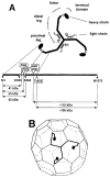
Figure 1. Schematic Representations of a Clathrin Triskelion, Showing Structural Subdivisions of a Leg and the Packing of a Triskelion in the Lattice of a Coat
(A) Correspondence between molecular morphology and positions in the polypeptide chain. The diagram is based on results from single-molecule electron microscopy, limited proteolysis, sizing chromatography, and primary structure determination (Schmid et al., 1982; Kirchhausen et al., 1983; Ungewickell, 1983; Kirchhausen and Harrison, 1984; Kirchhausen et al., 1987a). Selective proteolytic cleavage sites in the native molecule are boxed. (B) A typical lattice for a clathrin coat, with a single triskelion superimposed. Each leg of a triskelion contributes to two adjacent edges. The linker and terminal domain project inwards. The figure is based on results from electron microscopy (Crowther and Pearse, 1981; Heuser and Kirchhausen, 1985; Vigers et al., 1986).
Figure 2. Overall Structure of the Terminal Domain and Part of the Linker from the Rat Clathrin Heavy Chain The ribbon diagram shows the structure of the 55 kDa fragment of clathrin
The terminal domain (yellow) is a β propeller. The linker (red) is an α zigzag. The views in (A) and (B) include the first 487 amino acid residues of the clathrin heavy chain, which are visible in the electron density map in all the monomers in the crystallographic asymmetric unit. The view in (B) represents a 90° counterclockwise rotation about the vertical axis of the view in (A). The α helices are numbered α1 to α10. Blade 5 of the β propeller is labeled for orientation; loops 5a, 5b, 5c, and 5d project from the “bottom” surface of this blade. Figure was made with RIBBONS (Carson, 1991).
Figure 3. Ribbon Diagram of the Clathrin β Propeller Terminal Domain
The β propeller spans amino acid residues M1–E330. It has seven blades (1–7) organized sequentially in a counterclockwise direction and viewed here looking from the “top” to the “bottom” surface along the pseudo-7-fold axis. Within each blade, the orientations of the four β strands (a, b, c, and d) alternate, starting with the innermost strand, “a,” which runs from top to bottom, and ending with the outermost strand, “d,” which runs from bottom to top. Closure is achieved in blade 7 by the contributions of β strand 7d (residues P6 to H12) derived from the N terminus of the polypeptide chain. Figure was made with RIBBONS (Carson, 1991).
Figure 4. Structure-Based Sequence Alignment of Rat Clathrin Heavy Chain
(A) The sequence of the heavy chain (residues M1–E494) is shown with the elements of secondary structure indicated above the alignment. Yellow arrows mark β strands in the propeller; red cylinders, α helices in the linker. (B) Alignment of the seven blades within the β propeller of the terminal domain. The approximate boundaries of the strands are highlighted. ϕ designates conserved hydrophobic residues; W and D designate Trp and Asp. For comparison, the position of the WD repeat in bovine rod β transducin is shown (Sondek et al., 1996).
Figure 5. Structural Alignment of the Seven Blades in the Clathrin β Propeller
The figure shows a superposition of Cα traces for the seven blades of the clathrin β propeller, aligned using strands βb and βc of each blade. Blades 2, 3, 6, and 7 (yellow) have the shortest loops between β strands. Blades 1, 4, and 5 (red, green, and blue) have at least one long loop projecting from the top or the bottom surface of the β propeller. (A) and (B) correspond to views rotated by about 50° with respect to each other. (C) shows blade 1 of the β propeller from β-transducin (Sondek et al., 1996).
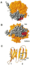
Figure 6. Mapping of Interaction Sites in Clathrin Terminal Domain Required for the Association with Nonvisual Arrestins
Residues of clathrin that participate in contacts with the C-terminal arm of arrestin3 and β-arrestin (Goodman et al., 1997) are shown in red in the space-filling representations (A and B) and as ball and stick models in the ribbon diagram (C). In (A) and (B), residues M1 to K100 are highlighted in gray; these correspond to blades 1 and 2 and to strand 7a. This segment by itself can bind to arrestin3 and β-arrestin (Goodman et al., 1997). The rest of the domain (residues A101 to E330) is yellow. The views in (A) and (B) are similar, respectively, to the top view in Figure 3 and to the side view in Figure 2A. The amino acid sequence of the segment of arrestin3 that binds this site is TNLIEFETN (Krupnick et al., 1997). Figure was made with RIBBONS (Carson, 1991).
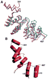
Figure 7. Structure of the α zigzag Region in the Clathrin Linker
(A) Superposition of Cα traces from the helical region of the three monomers (red, blue, green) in the crystallographic asymmetric unit. The superposition was obtained by alignment of the β propeller domains (not shown). (B) Cylinder representation of the α zigzag region of a monomer to show the overall right-handed twist in the linker region. Figure was made with Setor (Evans, 1993).
Figure 8. Relationship between the Clathrin Triskelion and the Structure of the Terminal Domain and Linker
Clathrin was deposited onto freshly cleaved mica by spraying in 50% glycerol, rotary shadowed with Pt, and visualized by electron microscopy (see Heuser and Kirchhausen, 1985). The ribbon diagram corresponds to the terminal domain and linker.
Similar articles
- Peptide-in-groove interactions link target proteins to the beta-propeller of clathrin.
ter Haar E, Harrison SC, Kirchhausen T. ter Haar E, et al. Proc Natl Acad Sci U S A. 2000 Feb 1;97(3):1096-100. doi: 10.1073/pnas.97.3.1096. Proc Natl Acad Sci U S A. 2000. PMID: 10655490 Free PMC article. - Arrestin/clathrin interaction. Localization of the arrestin binding locus to the clathrin terminal domain.
Goodman OB Jr, Krupnick JG, Gurevich VV, Benovic JL, Keen JH. Goodman OB Jr, et al. J Biol Chem. 1997 Jun 6;272(23):15017-22. doi: 10.1074/jbc.272.23.15017. J Biol Chem. 1997. PMID: 9169477 - Molecular switches involving the AP-2 beta2 appendage regulate endocytic cargo selection and clathrin coat assembly.
Edeling MA, Mishra SK, Keyel PA, Steinhauser AL, Collins BM, Roth R, Heuser JE, Owen DJ, Traub LM. Edeling MA, et al. Dev Cell. 2006 Mar;10(3):329-42. doi: 10.1016/j.devcel.2006.01.016. Dev Cell. 2006. PMID: 16516836 - Structure and Assembly of Clathrin Cages.
Halebian M, Morris K, Smith C. Halebian M, et al. Subcell Biochem. 2017;83:551-567. doi: 10.1007/978-3-319-46503-6_20. Subcell Biochem. 2017. PMID: 28271490 Review. - Getting in touch with the clathrin terminal domain.
Lemmon SK, Traub LM. Lemmon SK, et al. Traffic. 2012 Apr;13(4):511-9. doi: 10.1111/j.1600-0854.2011.01321.x. Epub 2012 Jan 13. Traffic. 2012. PMID: 22239657 Free PMC article. Review.
Cited by
- Does clathrin pull the fission trigger?
Di Paolo G, De Camilli P. Di Paolo G, et al. Proc Natl Acad Sci U S A. 2003 Apr 29;100(9):4981-3. doi: 10.1073/pnas.0930650100. Epub 2003 Apr 18. Proc Natl Acad Sci U S A. 2003. PMID: 12704235 Free PMC article. No abstract available. - Cryo-EM of multiple cage architectures reveals a universal mode of clathrin self-assembly.
Morris KL, Jones JR, Halebian M, Wu S, Baker M, Armache JP, Avila Ibarra A, Sessions RB, Cameron AD, Cheng Y, Smith CJ. Morris KL, et al. Nat Struct Mol Biol. 2019 Oct;26(10):890-898. doi: 10.1038/s41594-019-0292-0. Epub 2019 Oct 3. Nat Struct Mol Biol. 2019. PMID: 31582853 Free PMC article. - Vps41p function in the alkaline phosphatase pathway requires homo-oligomerization and interaction with AP-3 through two distinct domains.
Darsow T, Katzmann DJ, Cowles CR, Emr SD. Darsow T, et al. Mol Biol Cell. 2001 Jan;12(1):37-51. doi: 10.1091/mbc.12.1.37. Mol Biol Cell. 2001. PMID: 11160821 Free PMC article. - Clathrin regulates the association of PIPKIgamma661 with the AP-2 adaptor beta2 appendage.
Thieman JR, Mishra SK, Ling K, Doray B, Anderson RA, Traub LM. Thieman JR, et al. J Biol Chem. 2009 May 15;284(20):13924-13939. doi: 10.1074/jbc.M901017200. Epub 2009 Mar 14. J Biol Chem. 2009. PMID: 19287005 Free PMC article. - Coat/Tether Interactions-Exception or Rule?
Schroeter S, Beckmann S, Schmitt HD. Schroeter S, et al. Front Cell Dev Biol. 2016 May 17;4:44. doi: 10.3389/fcell.2016.00044. eCollection 2016. Front Cell Dev Biol. 2016. PMID: 27243008 Free PMC article. Review.
References
- Brünger AT. X-PLOR Version 3.1: A System for X-Ray Crystallography and NMR. New Haven, Connecticut: Yale University Press; 1992.
- Carson M. Ribbons 2.0. J Appl Crystallogr. 1991;24:958–961.
- Collaborative Computational Project Number 4. The CCP4 Suite: Programs for Protein Crystallography. Acta Crystallogr D. 1994;50:760–763. - PubMed
Publication types
MeSH terms
Substances
LinkOut - more resources
Full Text Sources
Other Literature Sources
Molecular Biology Databases
Research Materials


