Frank Lloyd Wright and the wood shingle roof - Frank Lloyd Wright Building Conservancy (original) (raw)
Membership Benefits
Join today and get discounts on tours, events, and more!
Own or maintain a Wright building?
Read technical information and case studies
Preservation in Action
By William J. Schwarz, AIA
Frank Lloyd Wright devoted unfailing attention and effort throughout his lifetime to adhere to his organic design philosophy, by which the various parts of a building would relate holistically and harmoniously to each other and to the character of the building as a whole. This attitude would give rise to continuity of the building elements, including the surface treatment of these elements. With respect to wood shingles as a roof covering, Wright gave particular attention to the way the textures and patterns of applied shingles could be made to continue gracefully from one roof surface to another as they pass across various hip and valley configurations, depending upon the geometry of a particular roof.
The roof was intended by Wright to be a major visual element of a building’s exterior. Distinctive in several ways from conventional architecture of the time, Wright’s roofs were configured with interesting forms that were a direct consequence of the geometry of the building’s floor plan, coupled with other considerations Wright gave to a project. These considerations included a desire to exhibit a powerful and comforting gesture symbolic of happy domesticity for the house’s inhabitants under a shelter that would offer generous protection from inclement weather, the sun’s rays, falling debris from overhead trees, or other potentially harsh environmental conditions. The roof elements were thus designed by Wright as practical and symbolic expressions of shelter.
When specifying wood shingle roofs, Wright invariably would specify cedar shingles to be installed incorporating a “modified Boston hip” treatment at hips and “closed valleys.” Exactly what the modifications were that Wright had in mind is a matter that is not often explained, but vintage photographs of the roofs at his own home Taliesin in Wisconsin (see below) reveal what he desired would be accomplished at roof hips.
It was Wright’s preference to install wood roof shingles in courses that continued across hips with only a slight embellishment that would be integral with the coursing, with no superimposition of overlaid hip and ridge units that have become ubiquitously utilized by roofers not given specific instructions to the contrary.
Hips
Wright’s pattern was usually to specify “modified Boston hips.” Some have referred to this manner of hip shingle construction as “braided” hips. The point to emphasize here is that Wright preferred that there should never be any stacking of hip shingle units of any kind applied over the field shingles. For each course, on each side of a roof hip, the field shingles are stopped short of the hip by the same dimension as that of their exposure, and a special-cut shingle is installed to extend from such stopping points to the hip line, and this shingle also extends (or is slid) about two-thirds downwards onto the exposure of the next-lower course. (This is not done for the starter course, though, where the field shingles on each roof plane are extended fully to the hip line and there mitered together.)
On account of this “sliding” down-slope of the tapered special-cut shingles, their weather-surfaces will become slightly depressed relative to the adjacent field shingles. I doubt that Wright concerned himself with this out-of-plane condition, but it may be addressed if desired by using longer shingles for the special-cut hip units (say 20-inch instead of 16-inch shingles—if 16” is the length being employed for field shingles). As an alternative to that, 3/8-inch solid stock could be used for the special-cut hip shingles and the upper portions of each hand planed so they conform to the surfaces of the adjacent field shingles. At symmetrical hips where roof planes of equal pitch meet, all special-cut hip shingles are paired, right- and left-hand, at each course and are either mitered or alternately lapped. Under each pair is first installed a concealed piece of sheet metal flashing folded over the hip, all of which must be installed progressing, course-by-course, from the eaves upwards, at the same time that field shingle courses are installed, sequentially, near the hips.
Serious consideration deserves to be given to the grain direction on the special-cut hip shingles. We see examples in historical photographs of the grain running in the same direction as that of the field shingles. Undue curling, splitting and breakage invariably occur in such instances, where slim pointed tips of the shaped shingles run perpendicular to the grain. It would be better to rotate the grain direction for the special-cut hip shingles so it runs parallel to the line of the hip.
This link to a detail for the American System-Built Houses shows Wright’s intent.
This photo of Taliesin circa 1912, in the collection of the Wisconsin Historical Society, shows Wright’s preferred hip treatment in the lower right.
The December 1982/January 1983 issue of Fine Homebuilding carried an article about roof shingle installation that included a discussion of Boston hips.
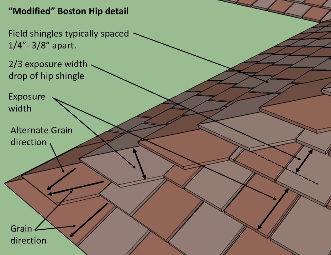
Modified Boston Hip drawing by John H. Waters, AIA
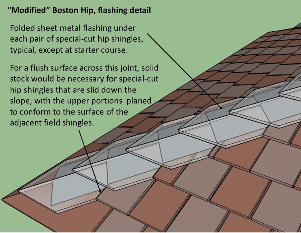
Modified Boston Hip drawing by John H. Waters, AIA
Ridges
Examples of Wright’s intent for ridges can be seen in historic photos of Taliesin. There Wright employed two treatments on roof ridges. Each was selected to present only straight-line profiles, and no application that has a saw-tooth pattern should ever be placed on the ridges. One treatment he used was straight cedar ridge-boards of the same thickness as the field shingle butts, or about 3/8”. The boards were most likely mitered, but possibly flush-lapped. Sometimes another treatment was employed that consisted of tightly butted field shingles, cut to very short lengths, with the grain on them running up the slope the same as for the field shingles. Installed, these presented smooth, continuous lines that appeared much like cedar ridge boards. Folded sheet metal ridge flashing should always be installed first underneath either the ridge boards or ridge shingles.
This historic photo of Taliesin shows the use of a straight ridge board.
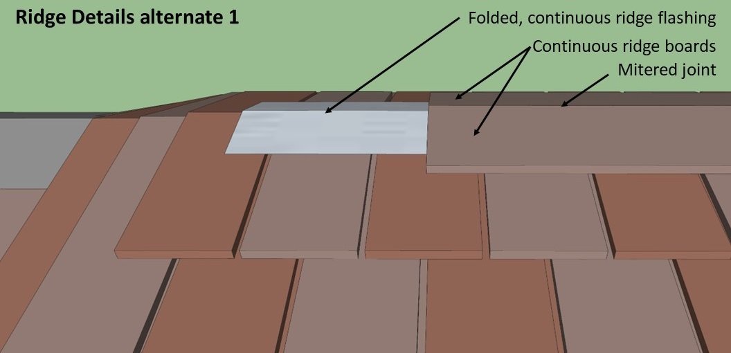
Ridge detail with straight cedar boards drawing by John H. Waters, AIA
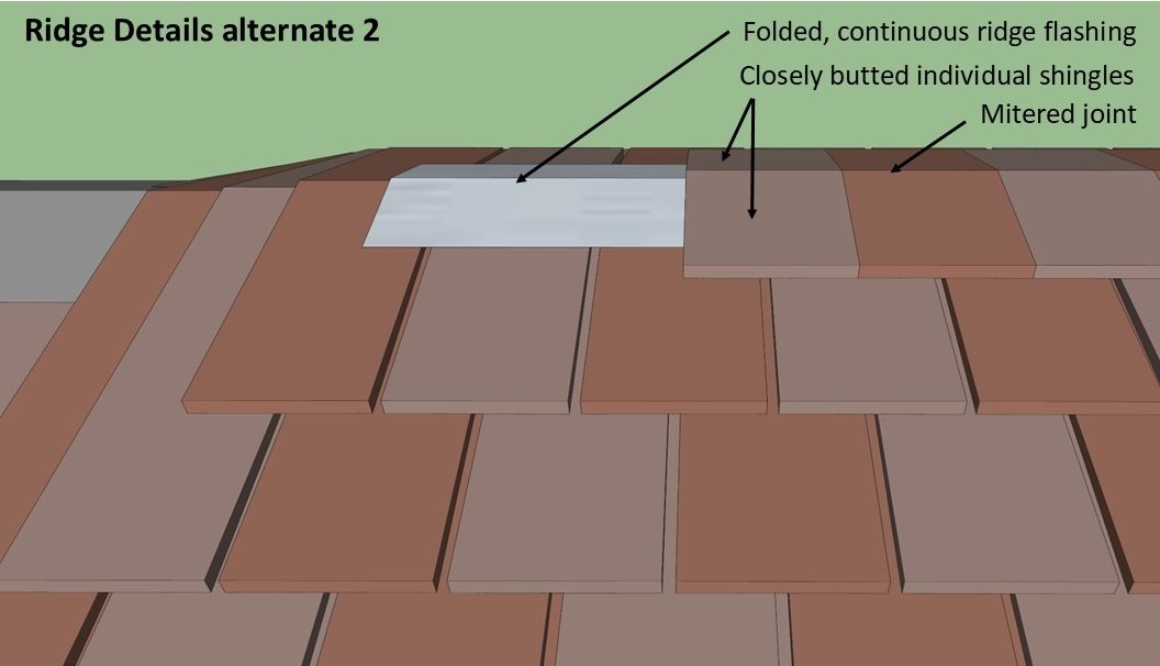
Ridge detail with closely butted shingles drawing by John H. Waters, AIA
Valleys
Valleys on the Taliesin roofs were always executed in “closed” style. It is true that debris tends to collect more readily in closed valleys than in open valleys, but Wright preferred them closed, so they were all constructed this way during his lifetime at Taliesin. Debris control would best be considered a maintenance issue and not one to determine the manner of shingling at valleys.
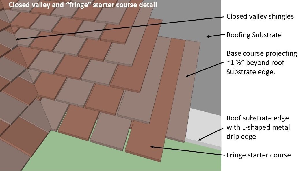
Closed valley detail drawing by John H. Waters, AIA
Starter course at eaves
Wright’s choice in his later years was to provide a quite unusual “fringe-like” effect with the starter courses on Taliesin roofs. Normally he would specify that the starter course for any shingled roofs be doubled, with the double thickness of butts projecting out 1-1/2 inches. But at Taliesin at least in the late 1950s, throughout the 1960s, and in some instances lasting even into the 1970s, the top layer of the doubled starter course of shingles projected out a distance of perhaps 3 inches past the line of butts of the bottom layer. This would at times cast patterns of bright sunlight streaks onto fascia boards and may also have encouraged patterns of icicles that pleased Wright—a very curious personal preference of his that likely was exclusive to Taliesin. If the typical field shingles are 16 inches long, then this top layer of the starter course would best be cut from twenty-inch-long shingles, although it is unlikely that Wright concerned himself with the issue.
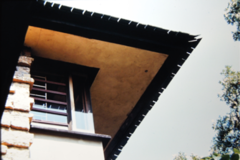
Photo taken in mid-1960s showing projecting second layer of shingles of starter course, creating “fringe” patterns at eaves that appealed to Wright in his later years. Photo by William J. Schwarz, AIA
Abutment of shingled roofs against vertical elements
Generally, the following discussion concerns the manner of providing watertight conditions at two such intersections at walls having stucco plaster finish. With respect to intersections with masonry, it is hoped that the existing sheet metal counterflashings will be found serviceable and reusable, but, if not, they would best be replaced in a manner that duplicates what now exists. Where shingle roofing abuts stucco along a level line, continuous sheet metal flashing would be bent up, with the vertical leg positioned behind the stucco. To accomplish this requires breaking away the stucco for the full height of said vertical flashing leg, plus an extra allowance for installation of concealed counterflashing, and anchorage of metal lath backing and base screed to which the replacement skirt of stucco plaster would be applied, extending down over the counterflashing to nearly the level of the shingles. Where shingles abut stucco finish on a slope, the flashing should be shingle style stepped flashing with individual pieces of metal extending out under each shingle course and their vertical legs positioned behind the stucco finish–all accomplished similarly as described above for level flashing, including the breaking out and replacement of the stucco plaster finish. The intent is to duplicate the existing manner of installation of metal flashings at abutting stucco plaster walls without any new application of surface-mounted or otherwise exposed sheet metal flashing or counterflashing provisions.
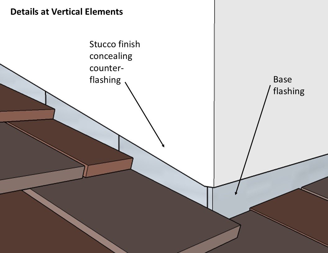
Details at vertical elements drawing by John H. Waters, AIA
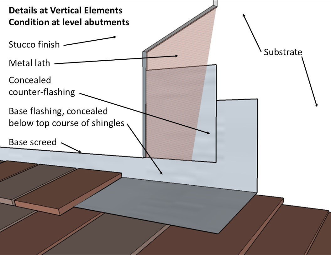
Details at vertical elements - condition at level abutments drawing by John H. Waters, AIA
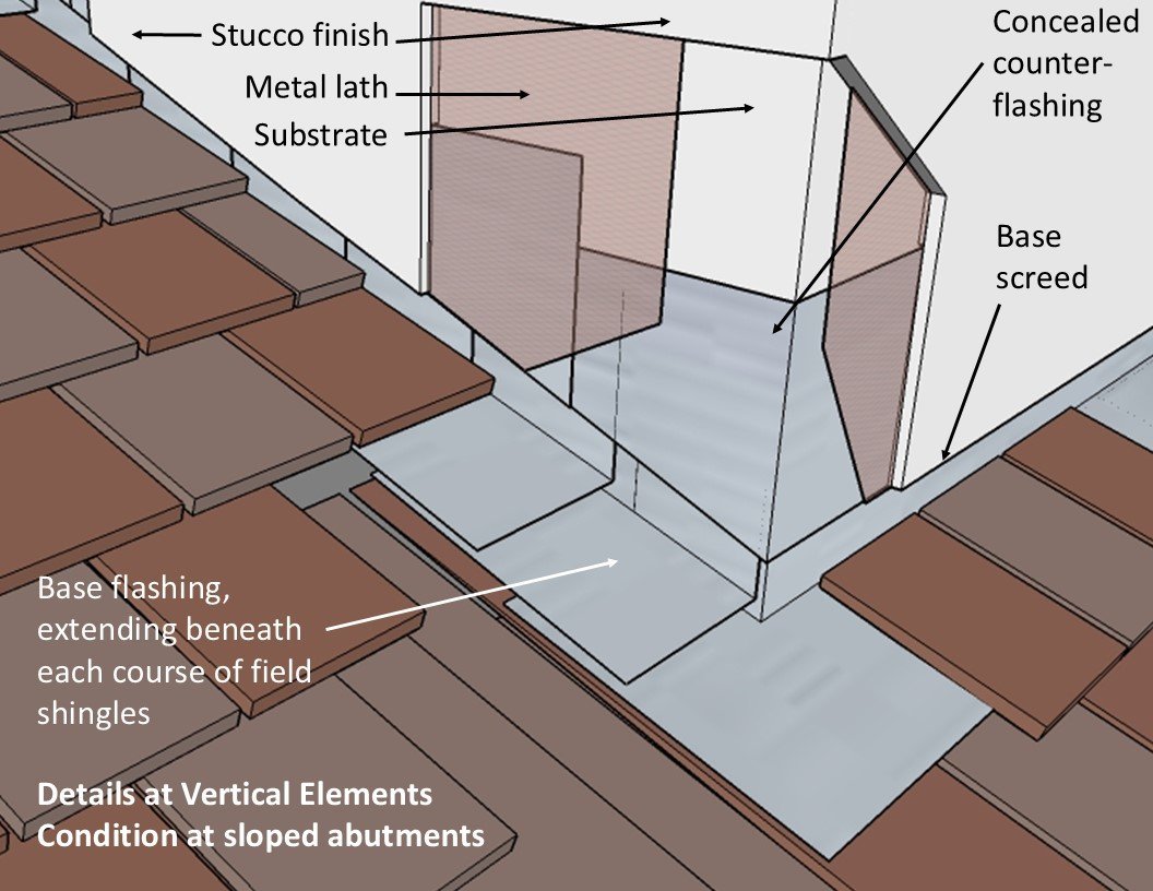
Details at vertical elements condition at sloped abutments drawing by John H. Waters, AIA
Mathews House
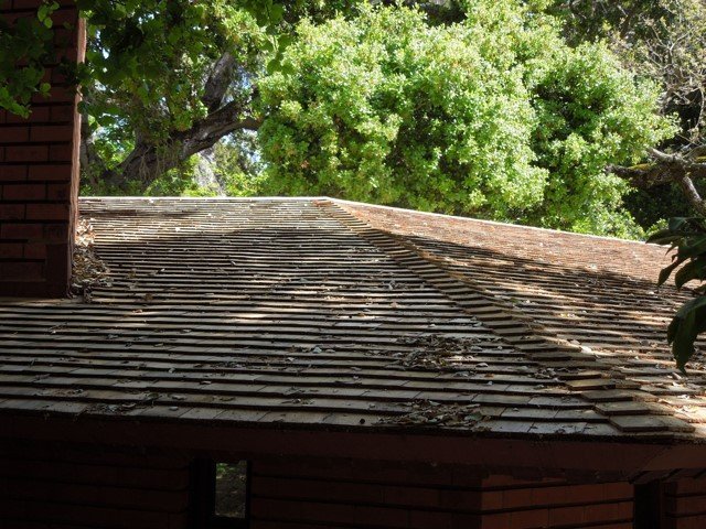
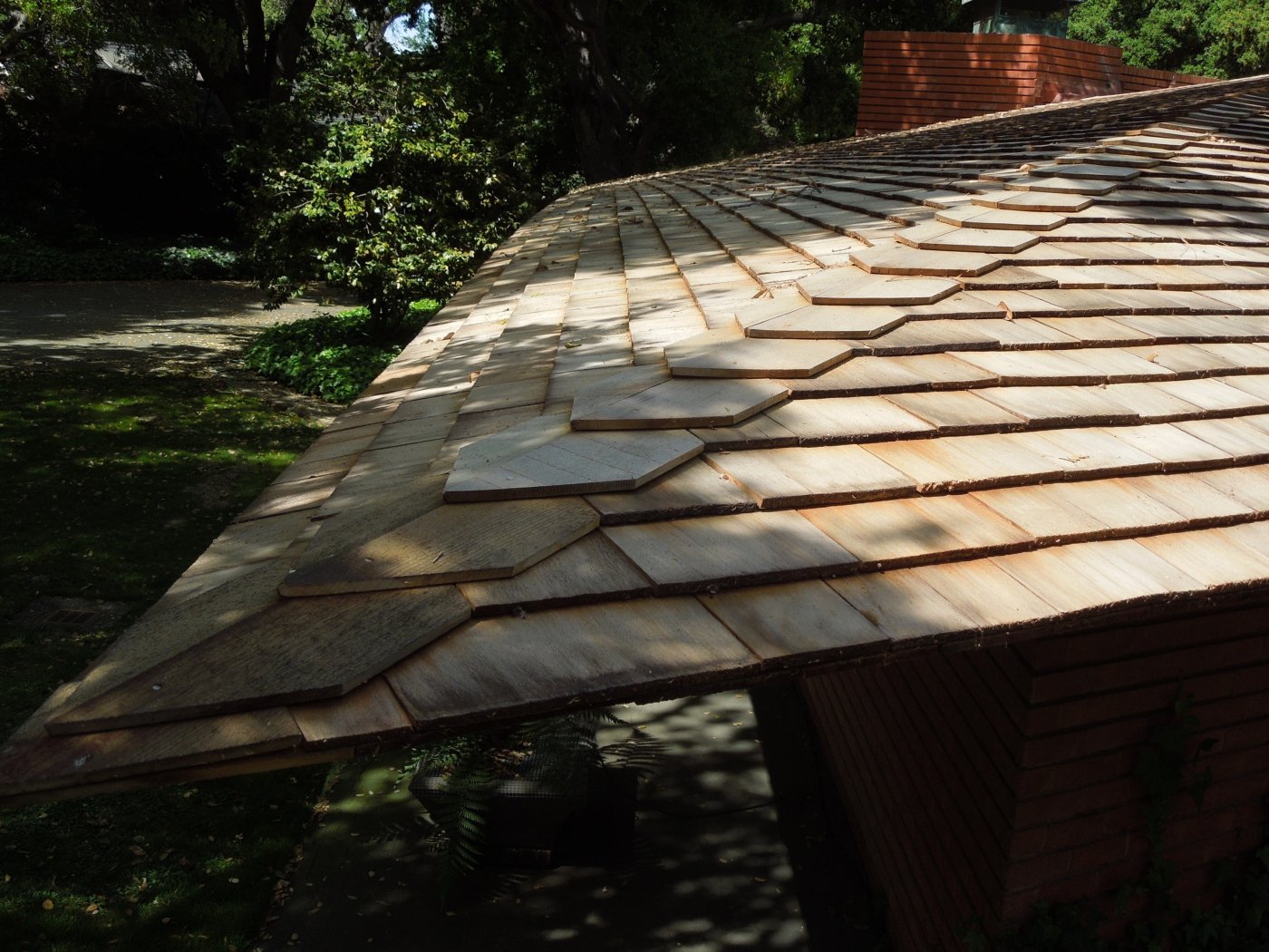
The 2016 restoration of the roof at the Mathews House, designed by Wright in 1950 in Atherton, California, provided an opportunity to detail the roof hips as generally intended by Wright. The geometry of the Mathews House plan complicated the process in that roof planes varied in slope. Where planes of the same slope met, the hip condition was as described above. Where planes of different slope met, custom hip shingles were designed to meet Wright’s goal of a smooth transition from one roof plane to another. Provisions were introduced at certain hips to terminate alternate shingle courses on the less steeply sloped roof surfaces that required narrower exposure to the weather than did the shingling on the adjacent roof surfaces pitched at a steeper slope.
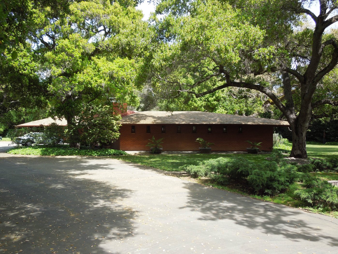
Mathews House, general view from southwest photo by William J. Schwarz, AIA
Mathews House from west, hip detail at living room, where two roof planes of the same slope meet photo by William J. Schwarz, AIA

Mathews House from southwest, hip detail at living room photo by William J. Schwarz, AIA
Mathews House from southeast, hip detail at living room photo by William J. Schwarz, AIA
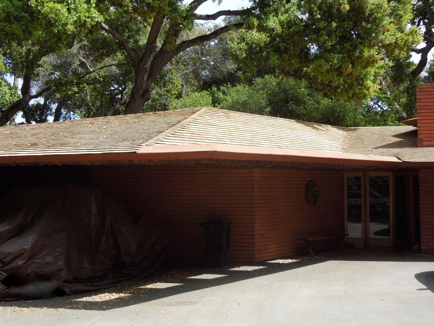
Mathews House from southwest, showing carport roof photo by William J. Schwarz, AIA
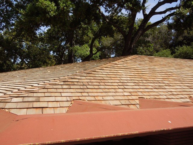
Mathews House from southwest, hip detail at carport roof photo by William J. Schwarz, AIA
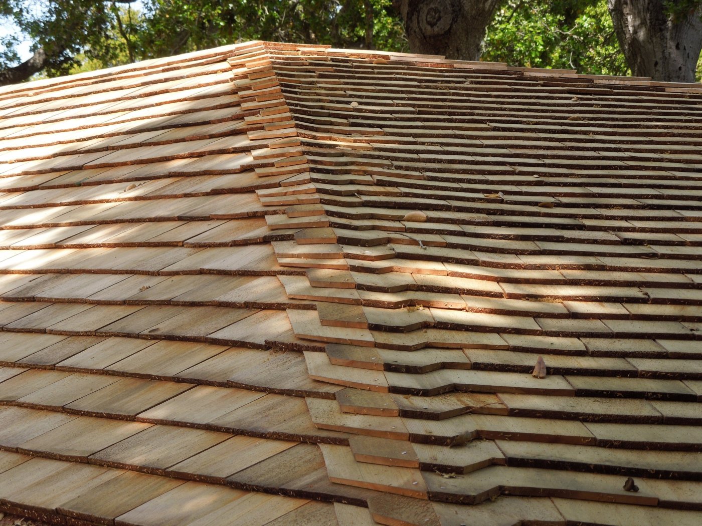
Restored roof at Mathews House, showing the junction of roof planes of different slopes having different shingle exposures to the weather photo by William J. Schwarz, AIA
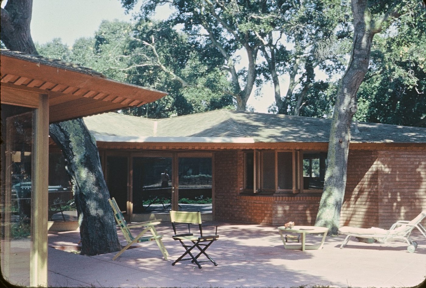
View of Mathews House from south, shortly after construction. Aaron Green is reflected in the glass. Photo courtesy of William J. Schwarz, AIA
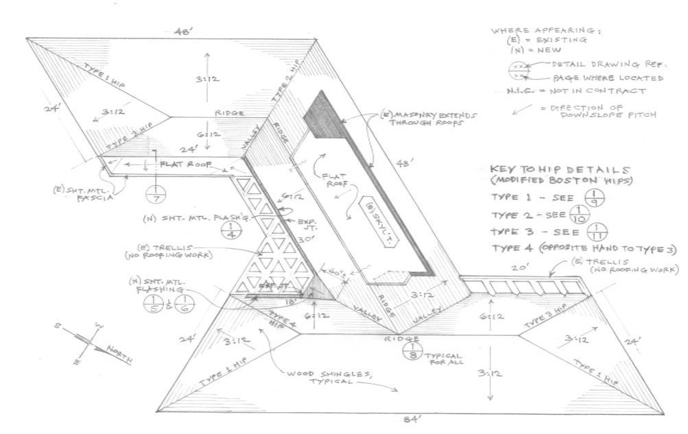
Mathews House, diagrammatic roof plan drawn by William J. Schwarz, AIA, all rights reserved
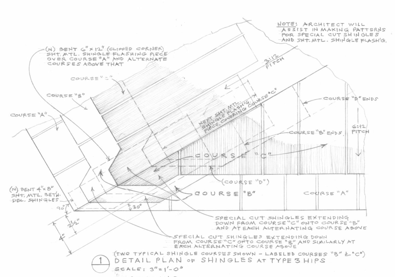
Mathews House, detail at junction of roof planes of different slopes having different shingle exposures to the weather drawn by William J. Schwarz, AIA, all rights reserved
Please Note: The details shown here are intended to provide information on the visual effects intended by Frank Lloyd Wright. Industry best practices should be adhered to for aspects including, but not limited to, underlayment and flashing.
Each restoration/maintenance/repair situation involving a Wright building requires analysis and research to identify the correct approach. The Conservancy is sharing this information so it may be of use to others as they evaluate their own specific situations and may consider these and other approaches. The Conservancy strongly recommends that owners consult with a design professional and an experienced contractor to determine which method is best for their specific projects.
Further, the provision of this information or mention of a specific product or products does not constitute endorsement, recommendation, preference or approval by the Conservancy.
Posted November 18, 2024