Review on the synthesis of doped TiO2 nanomaterials by Sol-gel method and description of experimental techniques (original) (raw)
Abstract
TiO2-based nanomaterials are very effective for water and air purification and act as good antibacterial agents due to their unique physicochemical properties. TiO2 is a promising nanocatalyst because of its non-toxicity, chemical stability, and low cost. The wide band gap and rapid electron-hole recombination limit its performance which can be overcome by doping with metals and non-metal ions. Metal doping improves the trapping of electrons to inhibit electron-hole recombination and non-metal doping reduces the bandgap of TiO2. These doped TiO2 materials can be synthesized by different routes like the Sol-gel method, hydrothermal method, precipitation method, impregnation method, etc. Among these, the Sol-gel method is reported as the best and most accurate for the synthesis of TiO2 particles in the nano scale range. Because it allows the incorporation of dopant ions at the molecular level with homogeneity and high chemical purity. The structural, morphological, and optical properties of as-synthesized TiO2 nanocatalysts can be well characterized by XRD, SEM, EDX, FT-IR, UV Vis-DRS, TEM, BET, and PL. In this review article, we would like to discuss the advantage of the Sol-gel method over other preparative methods of TiO2 nanomaterials and experimental techniques related to their characterization.
Figures (6)

Scheme 2. Schematic representation of precipitation synthesis route for the preparation of TiO, nanoparticles Scheme 1. Schematic representation of Hydrothermal synthesis route for the preparation of nanocrystalline TiO


Scheme 3. Schematic representation of impregnation synthesis route for the preparation of TiO, nanoparticles

Scheme 4. Schematic representation of impregnation synthesis route for the preparation of TiO, nanoparticles

Fig. 1. Diffraction of X-rays by crystal planes. After the line scan, the other set of coils (y.coils in this case) is used to deflect the beam slightly, and the scanning of the beam using the x coils is repeated. Thus, by rapidly moving the beam, the entire sample surface can be irradiated with the electron beam. The image of the sample is produced by using the output of a detector. Samples that conduct electricity are easier to study, for non- conducting samples, a metallic film produced by sputtering with metals like gold, palladium, or In a UV-vis.DRS spectrum the ratio of the light scattered from an infinitely thick layer and the scattered light from an ideal non-absorbing reference sample is measured as a function of the wavelength, \. The illumination of powdered samples by incident radiation leads to diffuse illumination of the samples. The incident light is
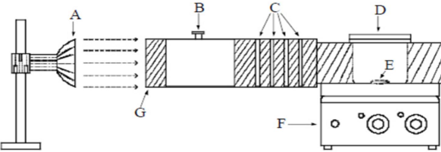
Fig. 2. Schematic representation of photo reactor. (A) light source; (B) UV filters; (C) circulating water (D) beaker with sample solu- tion; (E) magnetic paddle; (F) magnetic stirrer; (G) light channel

Loading Preview
Sorry, preview is currently unavailable. You can download the paper by clicking the button above.