Design and modeling of a continuously variable piezoelectric RF MEMS switch (original) (raw)
Abstract
order to achieve higher data rate or resolution in a miniaturized system with low power consumption, there is continued pressure to develop and improve small, high performance devices for manipulating rF signals at microwave, centrimetric and millimeter wave frequencies.
Figures (14)

Fig. 2 Key dimensions of RF MEMS switch structure

Fig. 1 Contactless RF MEMS switch structure


3.1 Capacitance Table 1 Key dimensions of RF MEMS switch considered later in this paper. The key dimensions of the device used for electrical testing, as marked in Fig. 2, are provided in Table 1. The structures for electri- cal testing were fabricated by bonding one Pyrex 7740 wafer, which carries the center electrode (which will be moved by piezoelectric actuation in the final device) to a second Pyrex 7740 wafer carrying the coplanar wave- guide using a patterned SU-8 bonding process. The use of a Pyrex substrate for the coplanar waveguide allows losses at high frequency to be reduced. In the proto- type switch developed later in the paper, the first Pyrex wafer carrying the moving conductor of the switch is replaced by a SOI wafer. The PZT actuation mate- rial and platinum electrodes are deposited on this SOI wafer. The device layer of the silicon-on-insulator wafer forms the cantilever part of the switch after the struc- ture is released, avoiding issues with residual stress and creep that are detrimental to the reliability of switches using metal or thin film bending structures (Rebeiz et al. 2013).

Fig. 3 Geometry used to model effect of cantilever material on trans- mission line to be negligible, and because the electric field is concen- trated in the gap between the CPW center conductor and ground, the cantilever was approximated with a flat plate positioned at a height equal to the separation at the center conductor edge.

Fig. 4 Effect of cantilever material on characteristic impedance of switch section try, the elliptic integrals were evaluated numerically using a

Fig. 5 Equivalent circuit including cantilever material

Fig. 6 Effect of fringing capacitance and cantilever material on insertion loss at 2 jm spacing

Fig. 8 Equipment for electrical measurements

Fig. 7 Comparison of electrical measurements with performance predicted by model
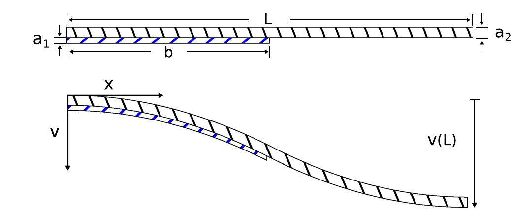
Fig. 9 Dimensions and deflected shape of beam The separated parts of the problem, firstly without the redun- dant moment reaction at the center of the beam, and secondly considering only this reaction, are illustrated in Fig. 10.

Fig. 11 Comparison of model and simulated deflected shape In a piezoelectrically actuated switch using a cantilever fixed at each end, the incremental capacitance at the center of the CPW center conductor is higher than at the edges.

Fig. 12 Isolation and insertion loss at various actuation voltages The predicted isolation (black curve) and insertion loss (red curve) of the prototype switch at various actuation voltages is plotted over the frequency range from 6 to 17 GHz in Fig. 12. The isolation and insertion loss obtained from the full model and by finite element simulation are similar to within 0.4 dB. Considering the frequency range from 6 to 14 GHz, the switch achieves insertion loss of less than 0.7 dB and isolation better than 10 dB with an actuation voltage of 22.4 V (from Sect. 5). As illustrated by the representative curve plotted for an inter- mediate actuation voltage of 16.5 V (blue curve), which gives a separation of 3 jm in the center of the coplanar waveguide, the state of the device can be continuously adjusted between the minimum capacitance (OFF) and maximum capacitance (ON) states, with a tunable range for capacitance of more than 15x.

Fig. 13 Predicted isolation and insertion loss of 30-40 GHz design

Loading Preview
Sorry, preview is currently unavailable. You can download the paper by clicking the button above.
References (19)
- Bayraktar O, civi O, akin T (2012) Beam switching reflectarray monolithically integrated with rf mems switches. Ieee Trans antennas Propag 60(2):854-862
- chen e, chou S (1997) characteristics of coplanar transmission lines on multilayer substrates: modeling and experiments. Ieee Trans Microw Theory Tech 45(6):939-945
- W, Mehregany M, Mullen r (1993) analysis of tip deflection and force of a bimetallic cantilever microactuator. J Micromech Microeng 3(1):4-7
- De Voe D, Pisano a (1997) Modeling and optimal design of piezo- electric cantilever microactuators. J MeMS 6(3):266-270
- Dehoff c, hennings a, Kugeler c, Schneller T, Bottger U (2011) Piezoelectric actuated mems for use in microwave switching and filtering applications. Phys Status Solidi a appl Mat Sci 208(2):343-356
- X, liu B, lv Z, li Z (2012) a lateral rf mems capacitive switch utilizing parylene as dielectric. Microsyst Technol 18(1):77-85
- Kim h, chun K (2007) rf mems technology. IeeJ Trans 2:249-261
- Ko c, ho K, rebeiz G (2013) an electronically-scanned 1.8-2.1 Ghz base-station antenna using packaged high-reliability rf mems phase shifters. Ieee Trans Microw Theory Tech 61(2):979-985
- Marcelli r, Bartolucci G, Papaioannu G, De angelis G, lucibello a, Proietti e, Margesin B, Giacomozzi F, Deborgies F (2010) reli- ability of rf mems switches due to charging effects and their cir- cuital modelling. Microsyst Technol 16(7):1111-1118
- Papaioannou G, exarchos M, Theonas V, Wang G, Papapolymerou J (2005) Temperature study of the dielectric polarization effects of capacitive rf mems switches. Ieee Trans Microw Theory Tech 53(11):3467-3473
- Polcawich r, Judy D, Pulskamp J, Trolier-McKinstry S, Dubey M (2007) advances in piezoelectrically actuated rf mems switches and phase shifters. In: Ieee MTT-S International Microwave Symposium Digest, pp 2083-2086
- G, Muldavin J (2001) rf mems switches and switch circuits. Ieee Microw Mag 2:59-71
- G, Patel c, han S, Ko c, ho K (2013) The search for a reli- able mems switch?: metal-contact switches. Ieee Microw Mag 14(1):57-67
- Schoenlinner B, Stehle a, Siegel c, Gautier W, Schulte B, Figur S, Prechtel U, Ziegler V (2011) The low-complexity rf mems switch at eads: an overview. Int J Microw Wirel Technol 3(5):499-508
- Smits J, choi W (1991) The constituent equations of piezoelectric heterogeneous bimorphs. Ieee Trans Ultrason Ferroelectr Freq control 38(3):256-270
- Timoshenko S (1925) analysis of bi-metal thermostats. J Opt Soc am 11(3):233-255
- Van caekenberghe K (2009) rf mems on the radar. Ieee Microw Mag 10(6):99-116
- Veyres c, Fouad hanna V (1980) extension of the application of con- formal mapping techniques to coplanar lines with finite dimen- sions. Int J electron 48(1):47-56
- Zhang l, Zhao Y (2003) electromechanical model of rf mems switches. Microsyst Technol 9(6-7):420-426