Modelling and multiobjective optimization analysis of a permanent magnet synchronous motor design (original) (raw)
Abstract
An alternative to traditional low-speed/high-torque drive systems, which are currently used in industry, could be the use of a permanent magnet synchronous motor directly coupled to the load and running at low speed, instead of the induction motor along with its mechanical transmission parts. The paper—in this context—deals with the analytical design procedure, optimization, and evaluation of such a motor (5 kW/50 rpm) and focuses on 2 topologies, ie, with inner and outer rotor. Finite element method designs of the permanent magnet machines are implemented as solutions of a complex optimization problem and several goals (multiobjectives) are considered (ie, machine weight minimization or efficiency maximization) with respect to relevant constraints. Three optimization methods are adopted and applied and a weighted cost function is proposed. The effectiveness of our problem design formulation approach and the use of these methods, in finding alternative and competitive permanent magnet synchronous motor designs, are also evaluated. The results reveal satisfactory design solutions and present acceptable performance. Moreover, by means of simulations, the application of several commercially available ferromagnetic materials for the motors' stator and rotor cores is performed. Last but not least, the effect of pole-arc per pole-pitch ratio along with the magnets length variation is also investigated. KEYWORDS computer aided design, finite element method, modelling and optimization, permanent magnet synchronous motors
Figures (21)
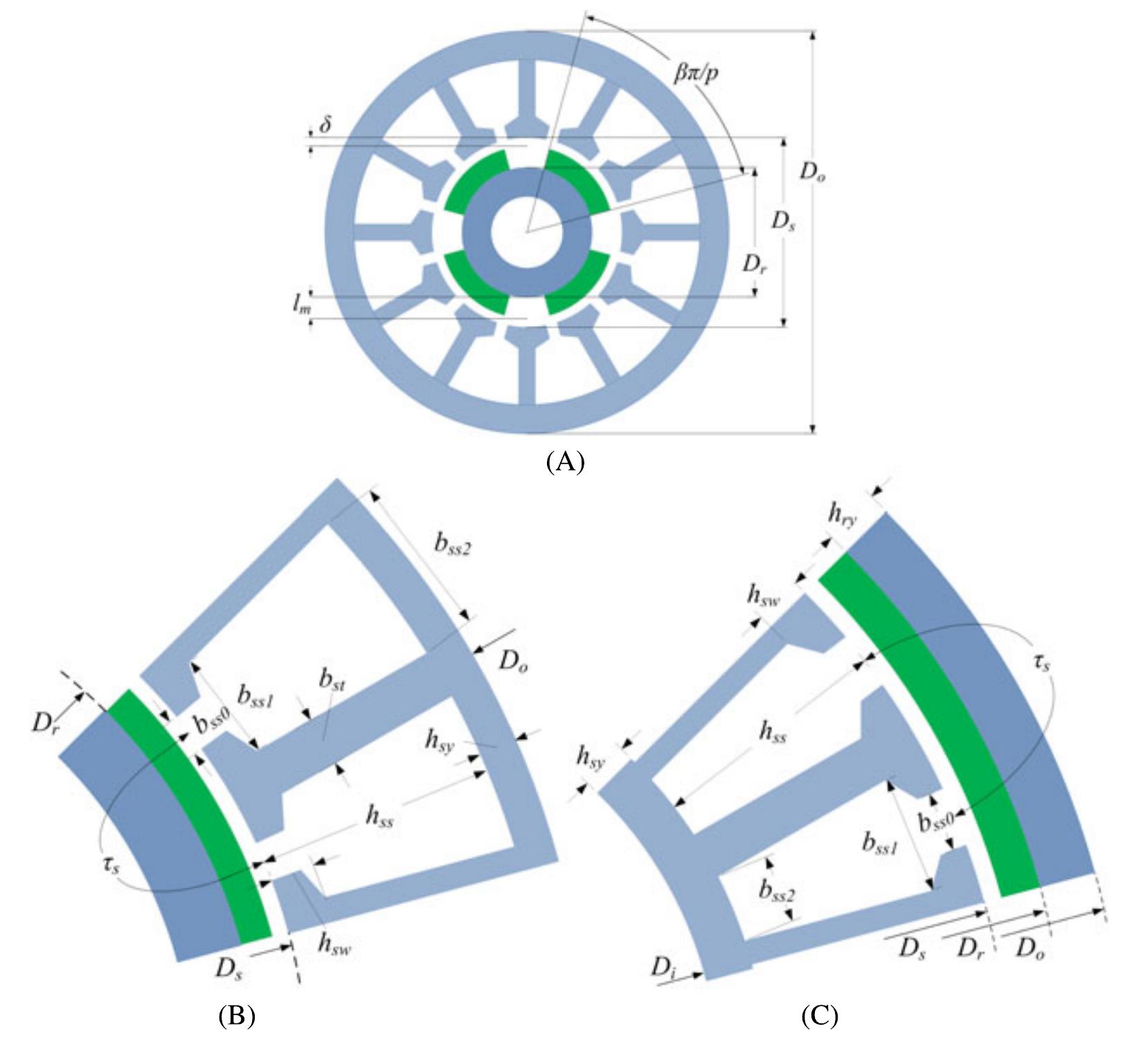
FIGURE 1 Geometrical representations for the permanent magnet synchronous motor designs under study. A, General cross section (inner rotor). B, Detailed slot geometry (1 pole pair) with inner rotor configuration. C, Detailed slot geometry (1 pole pair) outer rotor configuration The paper aims to provide a rigorous insight in the PMSM design modelling and optimization problem through finite element method (FEM) as well as to investigate the effec- tiveness of specific optimization algorithms regarding their ability to find solutions of PMSM designs (as competitive alternatives) to replace conventional industrial gearbox-low speed drive systems equipped with induction motors. The work performs also a systematic parametric investigation aiming to determine (1) the effects of certain variables vari- ation and (2) the influence of the core material used, to the reached optimized PMSMs. The organization of the work is as follows: The relative geometrical topologies and the nec- essary mathematical background of the overall motor design procedure are presented at Section 2, while the adopted procedure are presented at Section 2, while the adopted In radial flux PMSM, the current flows axially, while the magnetic flux flows radially inside them. Figure | depicts a generic cross section as well as detailed geometrical represen- tations of the configurations under study.*

where py, the relative permeability of the magnets, K jeax express the flux lines flowing through the air-gap (in percent)—called leakage factor—and B, is the magnet’s remanence flux density. By performing magnetostatic FEM simulations, it is easy to obtain the leakage factor. In this way, a simple although accurate linear relationship of k eax regarding the PMSM poles p can be used!”
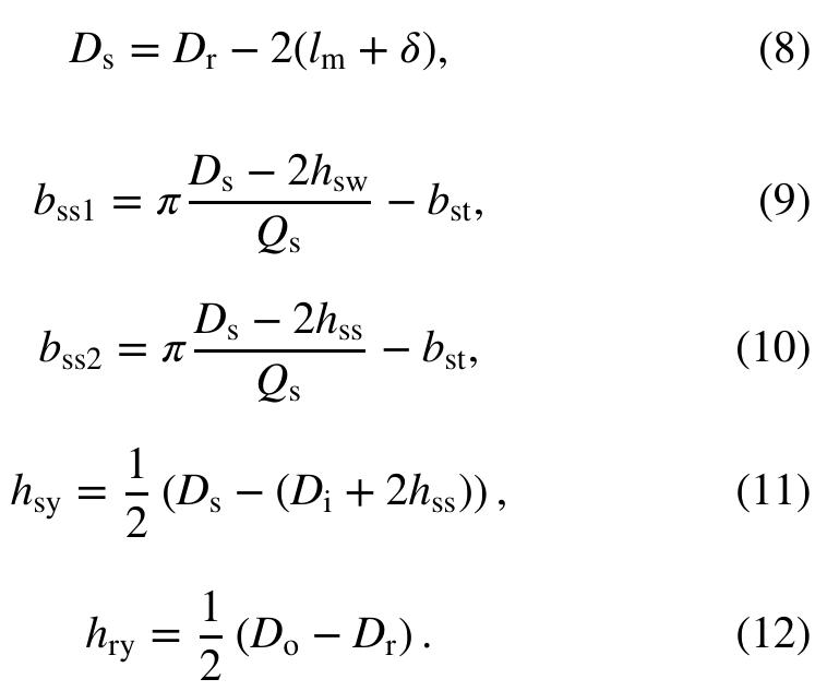
It should be stated here that, for both configurations, the widths of the slots shown in Equations 4 to 5 and Equations 9 to 10, are considered as straight lines (and not arcs as they compared to the pitch of the slot rt, is large enough.

FIGURE 2 Typical permanent magnet motors drive setup (through the optimization of the rotor geometry) can be jus- tified, by observing Equation 16. Because of the frequency square proportionality of the eddy current losses, the latter dominate in high speeds only. However, the hysteresis losses are prevail here, because the frequency used in our cases is higher than its fundamental component.

Abbreviations: FMC, Fmincon; GA, genetic algorithm; PMSM, permanent magnet synchronous motor; PS, pattern search. TABLE1_ Results of PMSM design variables through FMC, GA, and PS optimization methods (inner rotor) TABLE2 Results of PMSM design variables through FMC, GA, and PS optimization methods (outer rotor) A and A@ are matrices, x, b, b®, 1’, and uw? are vec- tors; C(x) and C(x) are functions, which return vectors; and F(x) is a function that returns a scalar. Finally, F(x), C(x), and C*/(x) can be nonlinear functions. Three optimiza- tion methods were chosen and applied here for solving our problem expressed in the form of Equation 28. These are (1) Fmincon (FMC), (2) genetic algorithm (GA), and (3) pat- tern search (PS). These techniques have been proved robust and efficient enough to most engineering problems in the past. Moreover, since they are well known, their principles of operation have been extensively presented in the litera- ture, and therefore, no relative information is given here. For further implementation details, the reader can refer to the literature.2°*? Among several parameters a GA uses, the most important ones refer to the population size (Ps), the number of generations (G,,), the crossover rate (C;,), and the mutation rate (M,). These parameters are given here the following values: P; = 80, G, = 100, C,=0.75, and M,=0.05. Eighteen sets of d esign results were derived (3 methods x 3 objective functions x 2 rotor topologies). For the inner rotot topology, Table 1 design variables t! shows the optimization results of the 12 hrough FMC, GA, and PS and for each one of the cost functions applied (CF)-CF3). Table 2 shows the same results for t he outer rotor topology. For demonstration purposes, some O f the optimized designs obtained (objective function CF3) were visualized and are depicted in Figures 3 and 4, with respe ct to (w.r.t.) their geometry and their flux density distribution. From these tables and figures, it is ini- tially clear that all algorithms succeeded to satisfy all of the existing constraints and to converge to a-near-optimum desigr solution. As an example, the motor’s outer diameter is kept within satisfactory limits (24-42 cm, with a 20- to 50-cm con- straint). while the machine lenoth lies mainlv in the 10- tc

Abbreviations: FMC, Fmincon; GA, genetic algorithm; PMSM, permanent magnet synchronous motor; PS, pattern search.

TABLE3 Objective quantities results through FMC, GA, and PS optimization methods (inner rotor) Abbreviations: FMC, Fmincon; GA, genetic algorithm; PS, pattern search.

TABLE4 Objective quantities results through FMC, GA, and PS optimization methods (outer rotor) Abbreviations: FMC, Fmincon; GA, genetic algorithm; PS, pattern search.

FIGURE3 Typical design optimization results obtained. Geometry and flux density distribution for inner rotor topology and CF; objective function: A, Fmincon. B, genetic algorithm

FIGURE 4 Typical design optimization results obtained. Geometry and flux density distribution for outer rotor topology and CF; objective function: A, Fmincon. B, genetic algorithm

TABLE5 Computational cost (seconds) of optimization methods applied Abbreviations: FMC, Fmincon; GA, genetic algorithm; PS, pattern search.

TABLE 6 Slot current density (A/cm?) results of the 18 designs

IGURE5 B-H curves of the 12 additional (and commercially available) materials used here for permanent magnet synchronous motor stator and rotor cores Abbreviations: FMC, Fmincon; GA, genetic algorithm; PS, pattern search. weight are shown for inner and outer rotor geometries, respec- tively, (for the 3 cost functions and through the 3 algorithms used). It is seen that the quantities ranges (min-max) found are 22 to 122 kg, 71.4% to 89.05%, and 1.9 to 5.3 kg. These tables reveal that if, for example, the machine weight is the pri- mary objective (cost function CF), the outer rotor topology is the choice, with the GA “showing the way” by presenting an efficient (approximately 80%) and very light (approxi- mately 22 kg) motor, while keeping the magnet weight low enough (approximately 4 kg) as seen in Table 4. The second place goes to FMC method applied to the same geometry, while for the PS method, it can be said that fails to present satisfactory results of the same degree. In the case where the magnets weight is the primary objective (cost function CF;3), the same conclusions are true. Indeed, GA presents a solution with quite satisfactory efficiency (approximately 76.4%), low magnet weight (2.4kg), while keeping the total machine weight low (approximately 27.5 kg), as also shown in Table 4. Fmincon provides the second “alternative” again, in Table 4. Fmincon provides the second “alternative” again,
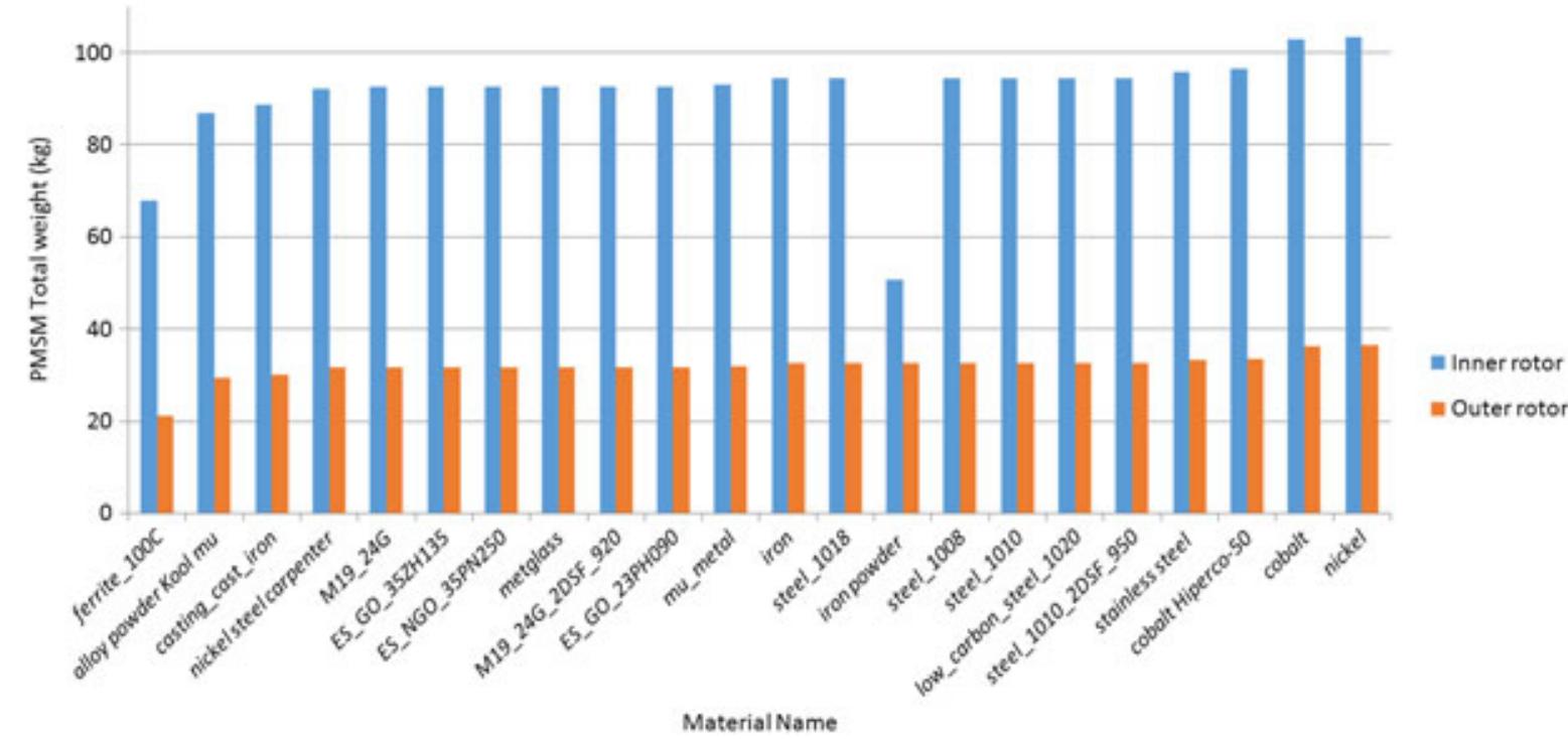
FIGURE 6 Effect of ferromagnetic materials (for stator and rotor cores) on optimized permanent magnet synchronous motor’s (PMSM’s) weight for int and outer rotor topologies (optimization method Fmincon, cost function CF;)

FIGURE7 Effect of variation of pole-arc per pole-pitch ratio # (x-axis to all subgraphs) and magnet length /,, (y-axis to all subgraphs) on 9 quantities c optimized permanent magnet synchronous motor with Fmincon method and cost function CF}. A, Inner rotor topology (see Figure 3A). B, Outer rotor topology (see Figure 4A). PM, permanent magnet The results obtained previously were calculated by incorpo- rating M19_24G as the stator and rotor core material and NdFe35 type for the PMs. M19_24G is a silicon nonori- ented (its magnetic properties are practically the same in any direction of magnetism in the plane of the material) electri- cal steel. It is commonly used in large generator, motors, and transformers, as it has superior permeability at high induc- Finally, Table 6 summarizes the thermal calculations results involving the slot current density for each one of the geometries found. As stated in Section 2.4, only 2 (outer rotor)

FIGURE 8 __ Effect of variation of pole-arc per pole-pitch ratio f (x-axis to all subgraphs) and magnet length /,, (y-axis to all subgraphs) on 9 quantities ¢ optimized permanent magnet synchronous motor with genetic algorithm method and cost function CF3. A, Inner rotor topology (see Figure 3B). B, Oute rotor topology (see Figure 4B). PM, permanent magnet Based on the above, the analysis took place with the appli- cation of 22 different materials. Ten of them were available through the commercial softwares database used, while the rest 12 were processed and incorporated by the authors. For the updating of the softwares database, the authors made an In every case, the same material was tested for both cores. We consider the geometries of the third cost function (CF3) optimized with FMC method (Figures 3A and 4A) since we choose that the magnet weight is of primary concern,
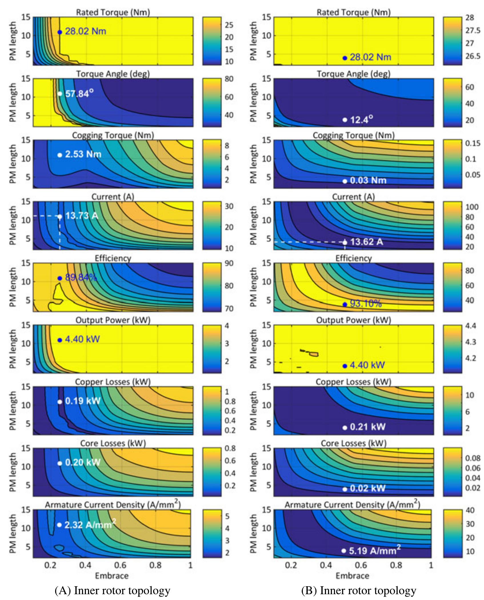
FIGURE9 Effect of variation of pole-arc per pole-pitch ratio # (x-axis to all sub-graphs) and magnet length 1, (y-axis to all sub-graphs) on 9 quantities of optimized permanent magnet synchronous motor with pattern search method and cost function CF. A, Inner rotor topology. B, Outer rotor topology. PM, permanent magnet the predefined efficiency. This is commented as an expected feature since the energy density of the magnets used is high enough. Therefore, Figure 6 depicts only the total machine weight recordings, where the material performance has been sorted out from lower to higher values. It can be seen that there are 9 materials that score lower machine weight val- ues than that of the M19_24G initially used. Based on that, from a manufacturer’s point of view, the material commer- cial cost is another crucial affecting factor in order for the machine designer to make an appropriate choice for a certain application. effort to retrieve real data from commercially available mate- rials in the free market™ and secondly proceed with data entry of the relative B-H curves of these materials as well as their properties, ie, bulk conductivity, mass density, using the software capabilities. For reference reasons, the B-H curves of the new (added) materials (along with their com- mercial names) are shown in Figure 5. By using one of the materials each time, simulations were performed and the val- ues of (1) the efficiency, (2) the output torque, and (3) the total weight of the PMSM were recorded. It was noticed that all of the materials achieved the required torque as well as all of the materials achieved the required torque as well as

TABLE7 Optimum combinations of embrace and magnet length (first 2 rows) for minimum PM weight and PMSM current and relative performance quantities Abbreviations: FMC, Fmincon; GA, genetic algorithm; PM, permanent magnet; PMSM, permanent magnet synchronous motor; PS, pattern search. 4.3 | Effect of pole-arc per pole-pitch ratio and magnet length been preoptimized already, the desired rated torque and output power are almost always satisfied for any of # and /,, combina- tion. Also, for easy reference purposes, a “dot” sign following by its corresponding value has been assigned to all subgraphs of Figures 7 to 9 . The best combination chosen actually exhibits the minimum motor line current (for maximum eco- nomic operation), while at the same time, the corresponding magnet weight can be considered as the minimum necessary quantity which ensures the desired nominal specifications during this economic operation. From a “decision-making” point of view, it is concluded that the inner rotor configuration preoptimized by GA method (Table 1) combined with best f and /m values of Table 7 presents the most attractive solution among the others. It exhibits low torque angle, low cogging torque, low current density, low magnet weight, low enough machine weight, low iron and copper losses, and the highest efficiency. Finally, it should be noted that the investigation, which took place in this subsection is judged as a necessary stage (refinement) in the modelling and optimization proce- dure proposed here, since the pole-arc to pole-pitch parameter has not been taken into account in the analytical calculation stage described in Section 2 and to which all methods adopted were based on.

TABLE A3__ Values of the constants involved in the design procedure

TABLE A2___ Design search variables and their universe of discourse

Abbreviation: PMSM, permanent magnet synchronous motor. TABLE A4_ Constraints of the PMSM design problem

Loading Preview
Sorry, preview is currently unavailable. You can download the paper by clicking the button above.
References (25)
- Vogel K, Rossa AJ. Improving efficiency in AC drives: comparison of topolo- gies and device technologies. Proceedings of Intl. Exhibition and Conference for Power Electronics, Intelligent Motion, Renewable Energy and Energy Management, PCIM, Nuremberg, Germany; May 20-22, 2014:509-516.
- Waide P, Brunner C. Energy-efficiency policy opportunities for electric motor-driven systems. Intl. Energy Agency (IEA) Working Paper, Paris, France (www.iea.org); 2011:11-17.
- Meier F. Permanent magnet synchronous machines with non-overlapping concentrated windings for low speed direct drive applications. PhD Thesis, Royal Institute of Technology, KTH, Stockholm, 2008.
- Libert F, Soulard J. Design study of a direct driven surface mounted per- manent magnet motor for low speed application. Proceedings of Intl. Sym- posium on Advanced Electromechanical Motion Systems, vol. 2, Marrakesh, Morocco; 2003:1-6.
- Ficheux R, Caricchi F, Crescimbini F, Onorato H. Axial-flux permanent magnet motor for direct-drive elevator systems without machine room. IEEE Trans Ind Appl. 2001;37(6):1693-1701.
- Spooner E, Williamson AC. Direct coupled permanent magnet generators for wind turbine applications. IEE Proc -Electr Power Appl. 1996;143(1):1-8.
- Dubois MRJ. Optimized Permanent Magnet Generator Topologies for Direct-Drive Wind Turbines. PhD Thesis, TU Delft, Delft University of Technology, 2004.
- Chen JY, Nayar CV, Longya X. Design and finite-element analysis of an outer rotor permanent magnet generator for directly coupled wind turbines. IEEE Trans Magn. 2000;36(5):3802-3809.
- Eriksson S, Bernhoff H, Bergkvist M. Design of a unique direct driven PM generator adapted for a telecom tower wind turbine. Renewable Energy. 2012;44:453-456.
- Krøvel Ø, Nilssen R, Skaar SE, Løvli E, Sandøy N. Design of an integrated 100kW permanent magnet synchronous machine in a prototype thruster for ship propulsion. Proceedings of 16th Intl. Conf. Electrical Machines, ICEM, Cracow, Poland; 2004:cd.ref. 697.
- Xianglin L, Kwok CT, Ming C. Analysis, design and experimental verifica- tion of a field-modulated permanent-magnet machine for direct-drive wind turbines. IET Electr Power Appl. 2015;9(2):150-159.
- Karnavas YL, Korkas CD. Optimization methods evaluation for the design of radial flux surface PMSM. Proceeding of Intl. Conf. on Electrical Machines, ICEM, vol. 1, Berlin, Germany; 2014:1348-1355.
- Pyrhonen J, Jokinen T, Hrabovcova V. Design of Rotating Electrical Machines, 2. Somerset, NJ, USA: John Wiley & Sons; 2013.
- Hassan W, Bingsen W. Efficiency optimization of PMSM based drive sys- tem. Proceedings of IEEE Intl. Conf. on Power Electronics and Motion Control, IPEMC, vol. 1, Harbin, China; 2012:1027-1033.
- Magnussen F, Sadarangani C. Winding factors and Joule losses of perma- nent magnet machines with concentrated windings. Proceedings of IEEE Intl. Conf. on Electric Machines & Drives, vol. 1, Madison, Wisconsin; 2003:333-339.
- Dorell DG. Combined thermal and electromagnetic analysis of permanent-magnet and induction machines to aid calculation. IEEE Trans Ind Electron. 2008;55(10):3566-3574.
- Hendershot JR, Miller TJE. Design of Brushless Permanent Magnet Machines. 2nd ed.: Motor Design Books LLC; 2010.
- Ponmurugan P, Rengarajan N. Multi-objective optimization of electrical machine, a state of the art study. Int J Comput Appl. 2012;56(13):26-30.
- ITT Flygt, Product catalogue, mixing products section (low speed). Available from: http://www.flygt.com/, Accessed on 10 Dec 2015.
- Optimizations Toolbox TM User's Guide. MA, USA: Matlab Release R2013b, The Mathworks Inc; 2013.
- Mitsuo G, Runwei C. Genetic Algorithms and Engineering Optimization. Canada: John Wiley & Sons; 2000.
- Eiben AE, Raué PE. Genetic algorithms with multi-parent recombination. Proceedings of Intl. Conf. on Parallel Problem Solving from Nature, LNCS, vol. 866. Springer-Verlag; 1994:78-87.
- Audet C, Dennis Jr JE. Analysis of generalized pattern searches. SIAM J Optim. 2003;13(3):889-903.
- Magnetic Material Database MagWeb. Available from: http://magweb.us/, Accessed on 4 Jan 2016.
- ANSYS Electromagnetic Suite (EM) v16: Maxwell 2D/3D User's Guide; 2015.