Modeling, Control and Power Management Strategy of a Grid connected Hybrid Energy System (original) (raw)
Abstract
This paper presents the detailed modeling of various components of a grid connected hybrid energy system (HES) consisting of a photovoltaic (PV) system, a solid oxide fuel cell (SOFC), an electrolyzer and a hydrogen storage tank with a power flow controller. Also, a valve controlled by the proposed controller decides how much amount of fuel is consumed by fuel cell according to the load demand. In this paper fuel cell is used instead of battery bank because fuel cell is free from pollution. The control and power management strategies are also developed. When the PV power is sufficient then it can fulfill the load demand as well as feeds the extra power to the electrolyzer. By using the electrolyzer, the hydrogen is generated from the water and stored in storage tank and this hydrogen act as a fuel to SOFC. If the availability of the power from the PV system cannot fulfill the load demand, then the fuel cell fulfills the required load demand. The SOFC takes required amount of hydrogen as fuel, which is controlled by the PID controller through a valve. Effectiveness of this technology is verified by the help of computer simulations in MATLAB/SIMULINK environment under various loading conditions and promising results are obtained. 1. INTRODUCTION Due to the considerations of environment condition, applications of renewable energy sources (RESs) are more promising; that makes environment pollution free. Also, their availability is cost free and continuous [1], [2]. Numerous RESs consist of photovoltaic system (PV), wind turbine system (WT) and micro-turbines, etc. which are considered as components of hybrid energy systems in the literature and also demonstrate applications of micro-grid [3], [4]. Due to the various seasonal and bad weather conditions such as temperature, wind speed, solar radiation and also geographical conditions, these structures are not worked properly. So, the solutions must be needed and find out. Hence, energy storage systems (ESSs) are suitable for the solution of the mitigation of wind effects, solar radiation fluctuations and also ESSs uphold the power and energy balance. Power quality also improves due to ESSs. Due to the fast variations of power, ESSs must contain a high power density as well as high energy density. So, it is required to keep more than one storage system for a hybrid energy storage system (HESS) [5]-[7]. The ESSs and battery banks (BBs) are efficiently used in hybrid energy systems (HESs). But, lifetime of batteries decreases due to the charging and discharging cycles [8], [9]. A secondary energy sources is required to enhance the supply energy reliability of HESs. Hence, a fuel cell (FC) is required to combine with the electrolyzer by giving a continuous supply to the load [10], [11]. The strategies of energy management consist of combination of PV, WT and FC comprising with electrolyzer as well as battery storage. These are most effective practice for quality of higher
Figures (9)
![Figure 1. Hybrid system connected to grid (Proposed Model) 2.1. Modeling of photovoltaic (PV) system Mathematical model of the PV system is shown in [15], [16]. The power characteristic of the P\ system is represented in [2]. To draw out the maximum power which is available in PV array, it is useful tc operate the PV system at MPPT. Maximum power point tracking (MPPT) is a process where PV array inverters which are connected to grid and other similar devices are employed to extract the maximum amount power. Hence, the PV module is designed with the help up MATLAB/SIMULINK by considering the following Equation (1). Also Table 1 contains specifications of the photovoltaic (PV) array.](https://figures.academia-assets.com/63968145/figure_001.jpg) ](
](Figure 1. Hybrid system connected to grid (Proposed Model) 2.1. Modeling of photovoltaic (PV) system Mathematical model of the PV system is shown in [15], [16]. The power characteristic of the P\ system is represented in [2]. To draw out the maximum power which is available in PV array, it is useful tc operate the PV system at MPPT. Maximum power point tracking (MPPT) is a process where PV array inverters which are connected to grid and other similar devices are employed to extract the maximum amount power. Hence, the PV module is designed with the help up MATLAB/SIMULINK by considering the following Equation (1). Also Table 1 contains specifications of the photovoltaic (PV) array.
![2.2. Modeling of electrolyzer Parameters considered to design the PV system such as Ip is the reverse saturation current of PV cell in [A], Isc is the short-circuit PV cell current in [A], Ipy/I,, is the output current of PV cell in [A], k is the boltzmann’s constant in [J/°K], a is the completion or ideality factor, q is the electron charge in [C], Rpis the PV cell containing parallel resistance in [Q], Rs is the PV cell containing series resistance in [Q], Ns is the no. of series cells in a string of the PV cell, Np is the No. of parallel strings, T is the temperature of the PV cell in [K], Vpy is the PV cell terminal voltage in volt in [V],Vyp is the voltage related to maximum power of the PV cell in [V], Vocis the PV cell open-circuit voltage in volt in [V]. a i a a Electrolyzer is used to decompose the water (H2O) into two elements, first one is hydrogen and another one is oxygen by circulating the electric current in the electrolyzer containing two separate electrodes. The process is called electrolytic process or electrolysis [11]. The electrolysis equation of water is shown below:](https://figures.academia-assets.com/63968145/table_001.jpg) ](
](2.2. Modeling of electrolyzer Parameters considered to design the PV system such as Ip is the reverse saturation current of PV cell in [A], Isc is the short-circuit PV cell current in [A], Ipy/I,, is the output current of PV cell in [A], k is the boltzmann’s constant in [J/°K], a is the completion or ideality factor, q is the electron charge in [C], Rpis the PV cell containing parallel resistance in [Q], Rs is the PV cell containing series resistance in [Q], Ns is the no. of series cells in a string of the PV cell, Np is the No. of parallel strings, T is the temperature of the PV cell in [K], Vpy is the PV cell terminal voltage in volt in [V],Vyp is the voltage related to maximum power of the PV cell in [V], Vocis the PV cell open-circuit voltage in volt in [V]. a i a a Electrolyzer is used to decompose the water (H2O) into two elements, first one is hydrogen and another one is oxygen by circulating the electric current in the electrolyzer containing two separate electrodes. The process is called electrolytic process or electrolysis [11]. The electrolysis equation of water is shown below:

Figure 2. A brief model of electrolyzer using Simulink From the Equations (3) and (4), an electrolyzer model is designed through the help of Simulink that is shown in Figure 2. 2.3. Modeling of storage tank
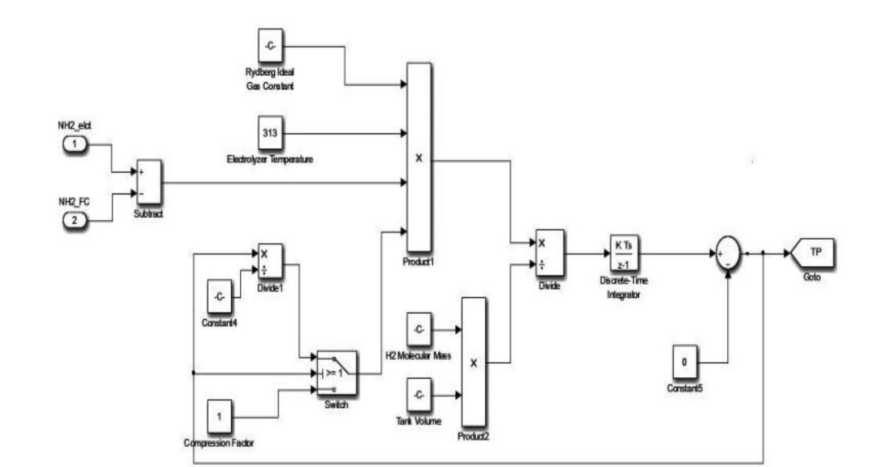
Figure 3. A brief model of hydrogen storage tank using Simulink 2.4. Modeling of solid oxide fuel cell (SOFC)


Figure 4. A brief model of SOFC system using simulink

Figure 5. A detailed block diagram of Hybrid Energy System (HES) The DC-link voltage is used to control the active power with its desired value. Output of the DC- link PI controller (ig*) acts as a reference of the current PI controller (active current controller) that is shown in Figure 5(c).

Figure 6. Detailed diagram of Hydrogen generation, control and output of boost converter connected across SOFC
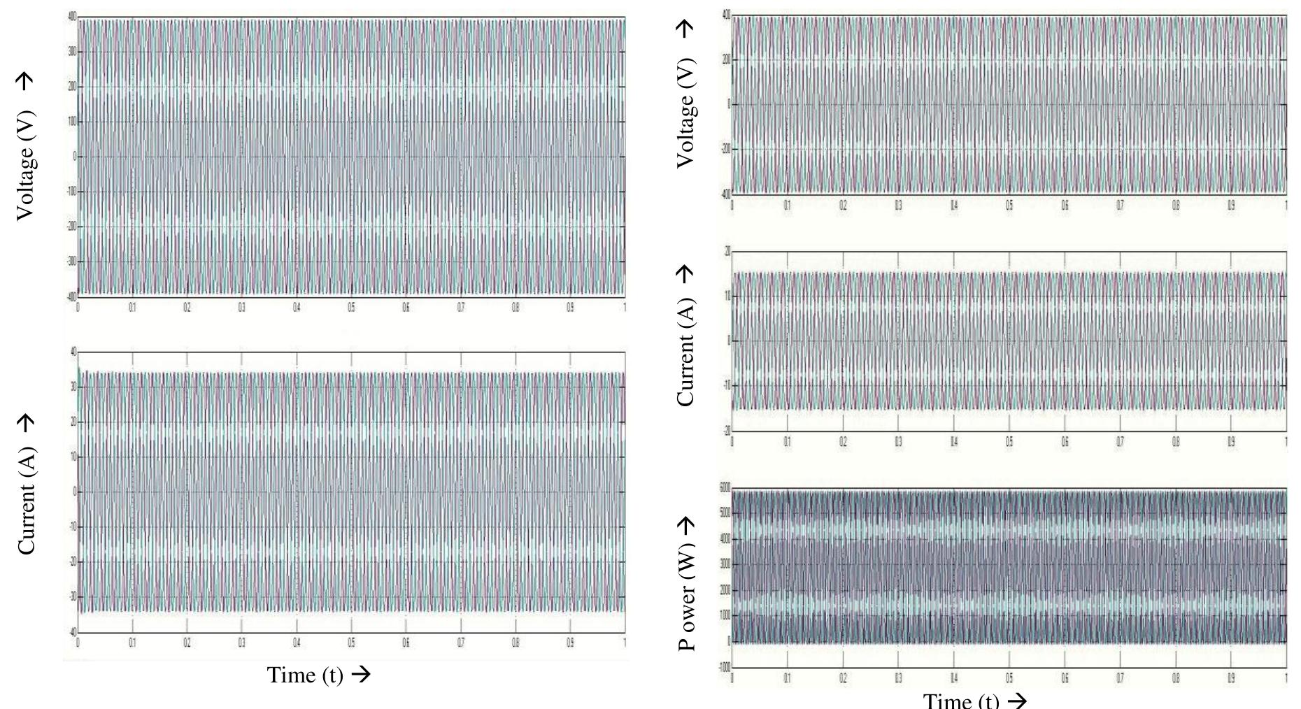
Figure 7. Output voltage and current of hybrid energy system (HES) Figure 8. Voltage, current and power of 3-phase load

Loading Preview
Sorry, preview is currently unavailable. You can download the paper by clicking the button above.
References (27)
- S.Tamalouzt, et al., "Performances analysis of WT-DFIG with PV and fuel cell hybrid power sources system associated with hydrogen storage hybrid energy system", International Journal of Hydrogen Energy, vol. 41, pp. 21006-21021, 2016.
- N. Benyahia, et al., "Modeling and simulation of a stand-alone wind/photovoltaic/fuel cell system associated with a hybrid energy storage", The 3rd International Renewable Energy Congress, Hammamet, Tunisia, pp. 20-22, December 2011.
- Y. Bouzelata, et al., "Exploration of optimal design and performance of a hybrid wind-solar energy system", International Journal of Hydrogen Energy, vol. 41, pp. 497-511, 2016.
- H. Yang, et al., "A novel optimization sizing model for hybrid solar-wind power generation system", Journal of Solar Energy, vol. 81, pp. 76-84, 2007.
- A. Etxeberria, et al., "Comparison of three topologies and controls of a hybrid energy storage system for microgrids", Energy Conversion Management, vol. 54, pp. 113-121, 2012.
- R. Balamurugan and R. Nithya, "FC/PV Fed SAF with Fuzzy Logic Control for Power Quality Enhancement", International Journal of Power Electronics and Drive System (IJPEDS), vol. 5, pp. 470-476, 2015.
- B. S. Sami, "An Intelligent Power Management Investigation for Stand-Alone Hybrid System Using Short-Time Energy Storage", International Journal of Power Electronics and Drive System (IJPEDS), vol. 8, pp. 367-375, 2017.
- N. A. Ahmed, et al., "Development of an efficient utility interactive combined wind/photovoltaic/fuel cell power system with MPPT and DC bus voltage regulation", Electrical Power Systems Research, vol. 81, pp. 1096-1106, 2011.
- A. Maleki and A. Askarzadeh, "Comparative study of artificial intelligence techniques for sizing of a hydrogen- based standalone photovoltaic/wind hybrid system", International Journal of Hydrogen Energy, vol. 39, pp. 9973-9984, 2014.
- S. Obara, et al., "Economic efficiency of a renewable energy independent microgrid with energy storage by a sodium-sulfur battery or organic chemical hydride", Internal Journal of Hydrogen Energy, vol. 38, pp. 8888-8902, 2013.
- R. Sarrias-Mena, et al., "Electrolyzer models for hydrogen production from wind energy Systems", International Journal of Hydrogen Energy, vol. 40, pp. 2927-2938, 2015.
- X. Liu, et al., "A hybrid AC/DC micro-grid and its coordination Control", IEEE Transactions on Smart Grid, vol. 2, pp. 278-286, 2011.
- H. Milanda, et al., "Load control of a wind-hydrogen stand-alone power system", International Journal of Hydrogen Energy, vol. 31, 2006, pp. 1215-1235.
- C. Wang and M. Hashem Nehrir, "Power management of a standalone wind/photovoltaic/fuel cell energy system", IEEE Transactions on Energy Conversion, vol. 23, pp. 957-967, 2008.
- N. H. Samrat, et al., "Modeling, control, and simulation of battery storage photovoltaic-wave energy hybrid renewable power generation systems for island electrification in Malaysia", Science World Journal, vol. 21, pp. 1-21, 2014.
- B. V. Rajanna, et al., "Solar Photovoltaic Generators with MPPT and Battery Storage in Microgrids", International Journal of Power Electronics and Drive System (IJPEDS), vol. 7, pp. 701-712, 2016.
- D. Rekioua, et al., "Development of hybrid photovoltaic-fuel cell system for stand-alone application", International Journal of Hydrogen Energy, vol. 39, pp. 1604-1611, 2014.
- T. Vigneysh, et al., "Operation and control of wind/fuel cell based hybrid micro grid in grid connected mode", IEEE International Multi-Conference on Automation, Computing, Communication, Control and compressed Sensing, pp.754-758, March 2013.
- S.Tamalouzt, et al., "Direct torque and reactive power control of grid connected doubly fed induction generator for the wind energy conversion", Tunisie Conference on International Sciences Technologies Electriques, Maghreb, Tunis, pp.1-7, November 2014.
- ISSN: 2088-8708
- Int J Elec & Comp Eng, Vol. 8, No. 3, June 2018 : 1345 -1356 1356
- F. Tazerart, et al., "Direct torque control implementation with losses minimization of induction motor for electric vehicle applications with high operating life of the battery", International Journal of Hydrogen Energy, vol. 40, pp. 13827-13838, 2015.
- C. N. Bhende, et al., "Permanent magnet synchronous generator-based standalone wind energy supply system", IEEE Transactions on Sustain Energy, vol. 4, pp. 361-373, 2011.
- O. C. Onar, et al., "Dynamic modeling, design and simulation of a wind/fuel cell/ultra-capacitor-based hybrid power generation system", Journal of Power Sources, vol. 161, pp. 707-722, 2006.
- M. Uzunoglu and O. C. Onar, "Static VAR compensator based reactive power Management for SOFC power plants", International Journal of Hydrogen Energy, vol. 33, pp. 2367-2378, 2008.
- G. K. Bayrak and M. Cebeci, "Grid connected fuel cell and PV hybrid power generating system design with Matlab Simulink", International Journal of Hydrogen Energy, vol. 39, pp. 8803-8812, 2014.
- M.G.Molina and E.J.Espejo, "Modeling and simulation of grid-connected photovoltaic energy conversion systems", International Journal of Hydrogen Energy, Vol. 39, pp. 8702-8707, 2014.