Comprehensive Analysis for Modernization of 100 t Electric Arc Furnace for Steel Production (original) (raw)
Abstract
In this paper is analyzing the current operating conditions of one of electric arc furnace (EAF) in order to evaluate the best option to solve the energy consumption problem. Also we evaluate existing process' equipment performance and point to improvement opportunities. Recommendations for the best operating set-points to run its EAF efficiently are presented. For compensating the reactive energy and increasing the power factor are presented three solutions. By the proposed automation solutions of the auxiliary installations is obtained a substantial reduction of the energy consumption and the defects of mechanical nature. The SVC compensation solution of the reactive energy is the best one, but has also the highest costs.
Figures (21)
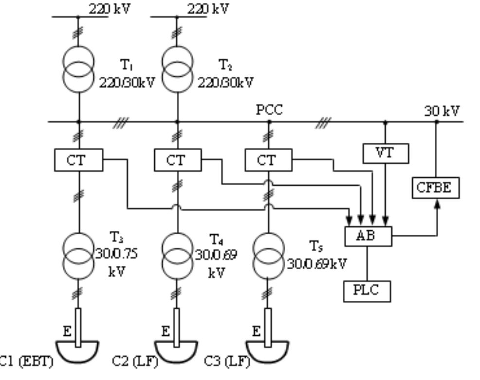
Figure 1. Power supply diagram. The electric diagram of the supply installation is presented in fig. 1. The compensation filtering and balancing equipment (CFBE) is connected on the medium voltage side (30kV).
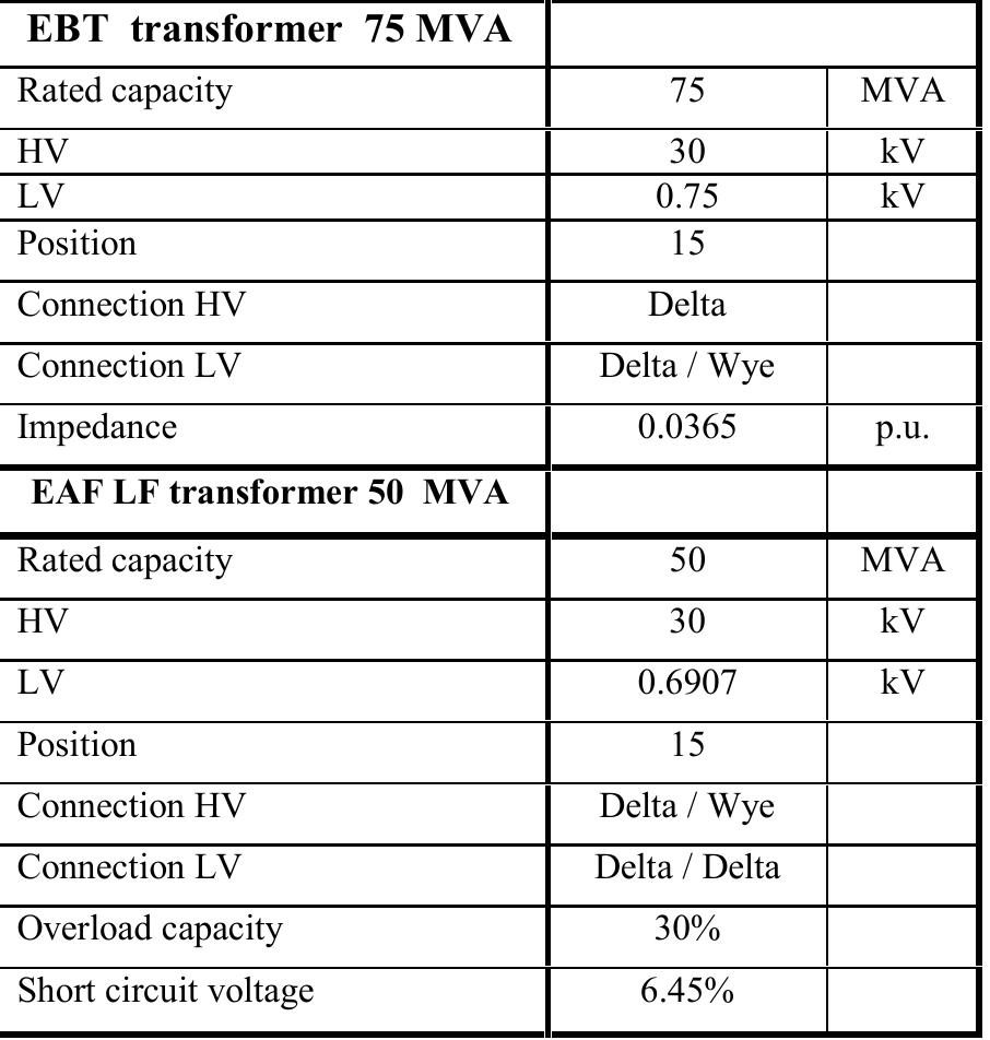
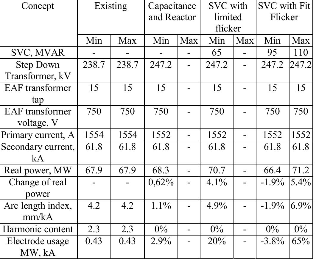
The characteristics of the transformer for this LF furnace ire given in Table I.
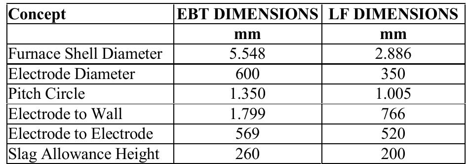
The electrode consumption is calculated, as follows: By T, and T> were noted the power transformers from the power station, T3 is the transformer of the furnace C, (EBT), T4 and T; the transformers of the furnaces for steel’s treatment and alloy C, and C; (LF) and by E, the electrodes. The furnaces’ currents and voltages are acquired from the 30 kV bus-bars which, by means of the automated block (AB) and the PLC) which controls the entire process, is analyzed and controlled the compensation and filtration installation (CFBE), aiming the reduction of the currents’ and voltages’ deformation evel, increase of the power factor and reduction or even elimination of the current and voltage superior harmonics. The furnaces’ geometric dimensions are presented in table II.
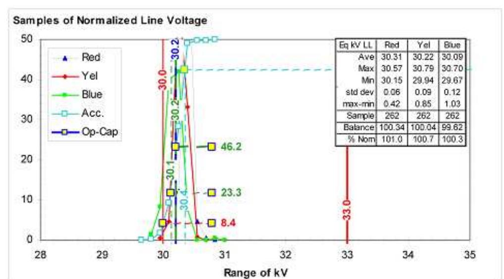
Figure 3. Normalized line voltage. Figure 2. Secondary current profile.
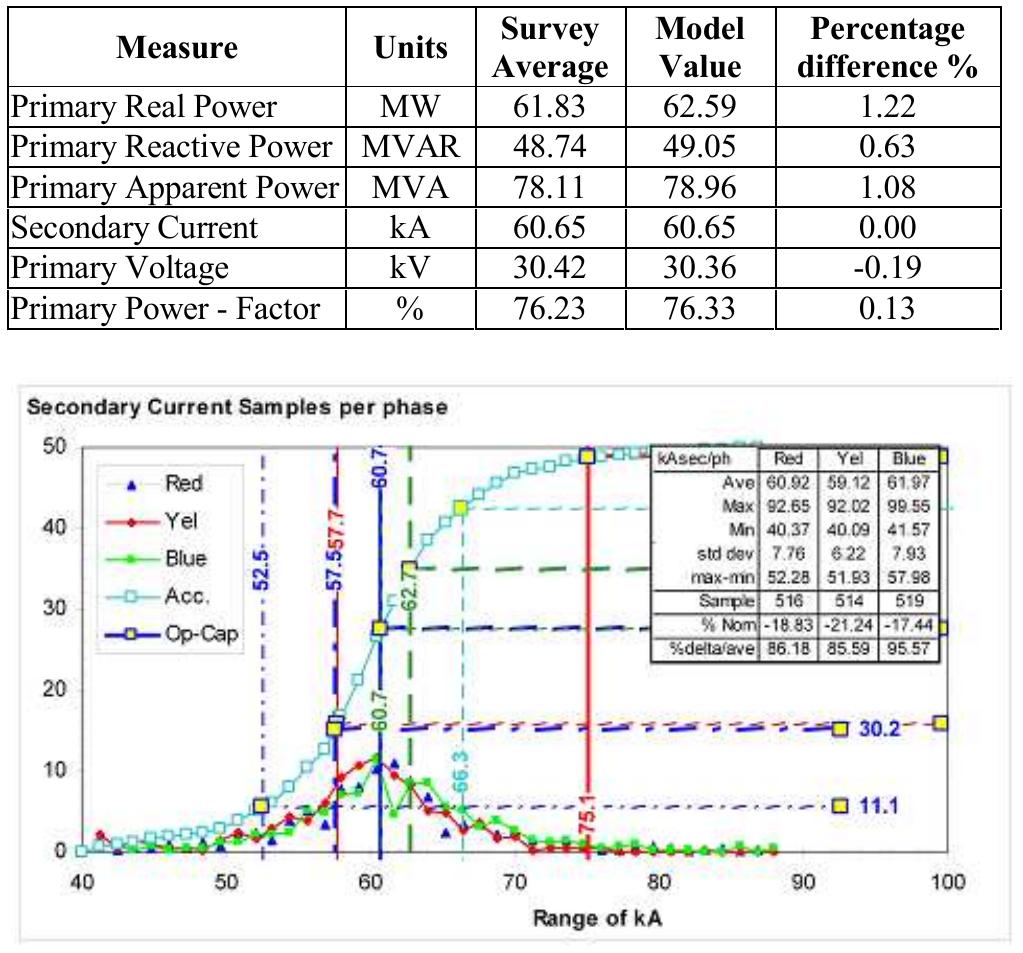
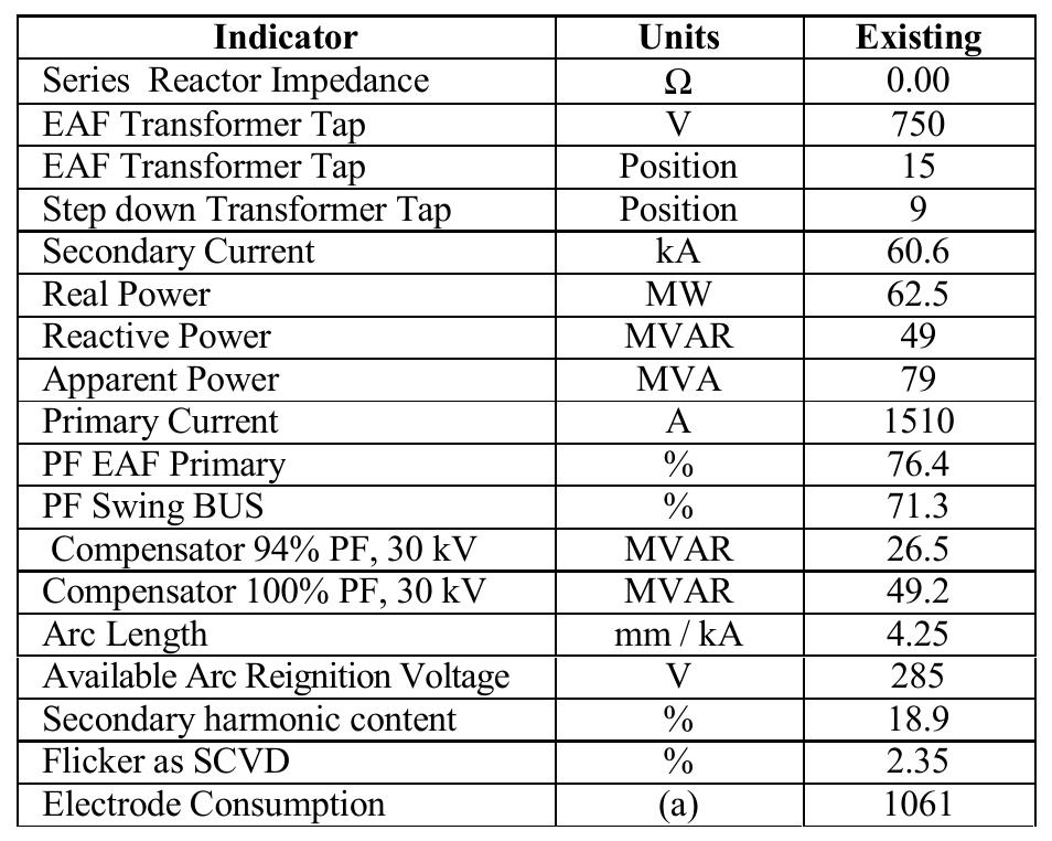
In table IV are presented the main indicators of the melting wrocess itself (early melt).
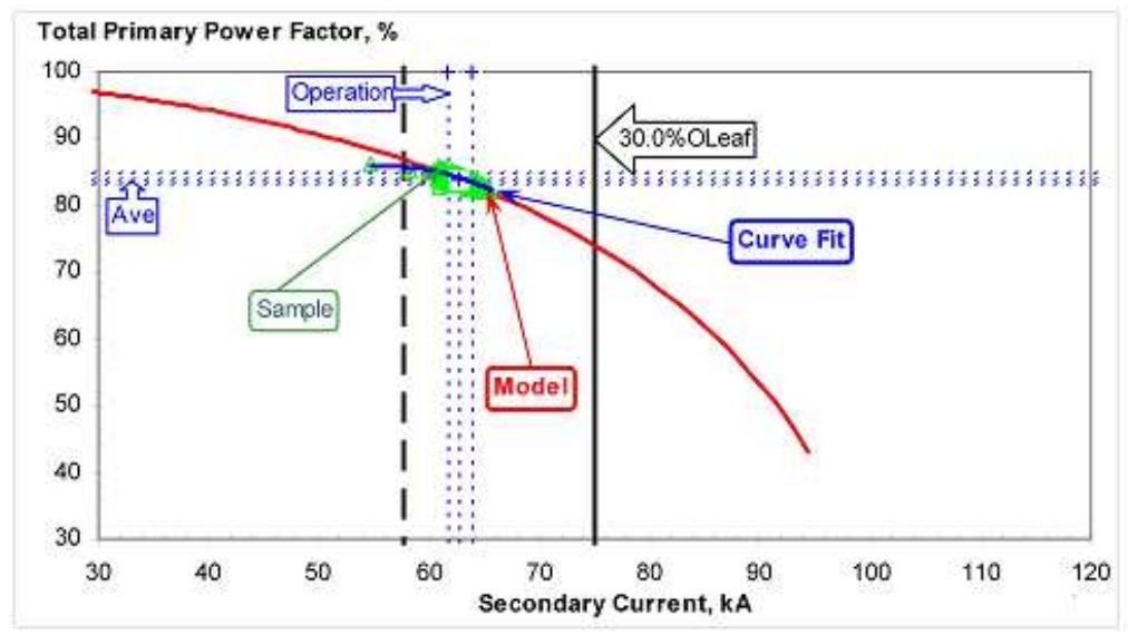
Figure 4. Power factor.
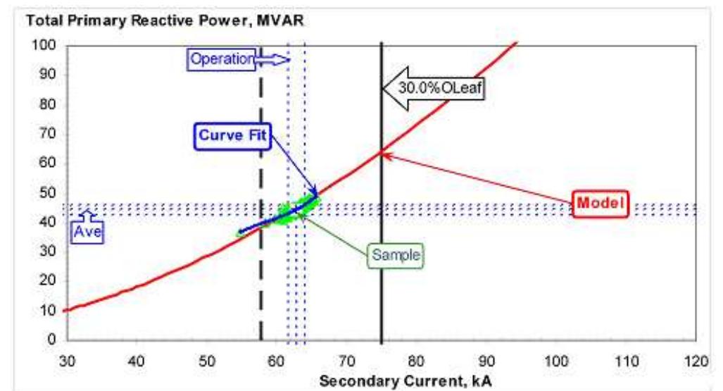
Figure 5. Totally reactive power
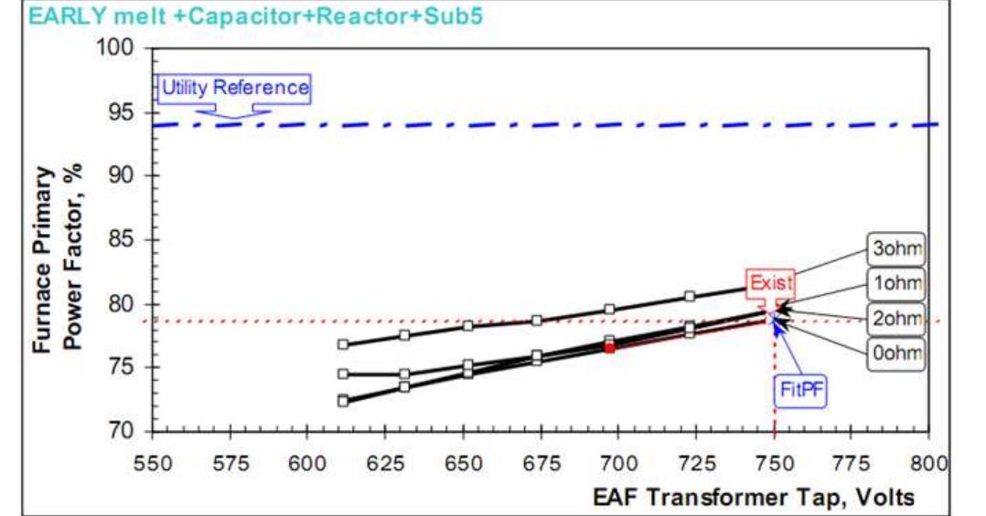
Figure 8. Primary power factor Figure 7. Reactive power consumption with series reactor loading
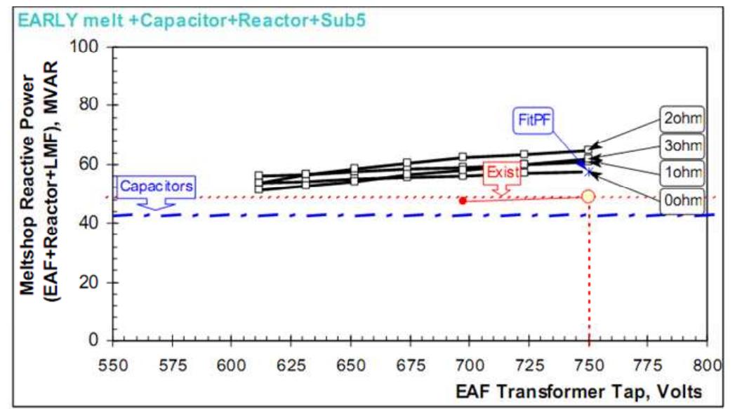
Figure 6. Reactive power consumption with LF furnace
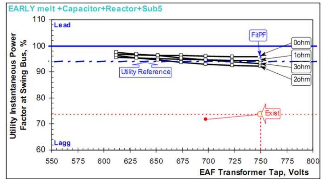
Figure 9. Power factor at swing bus
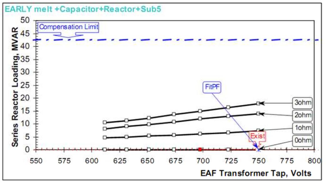
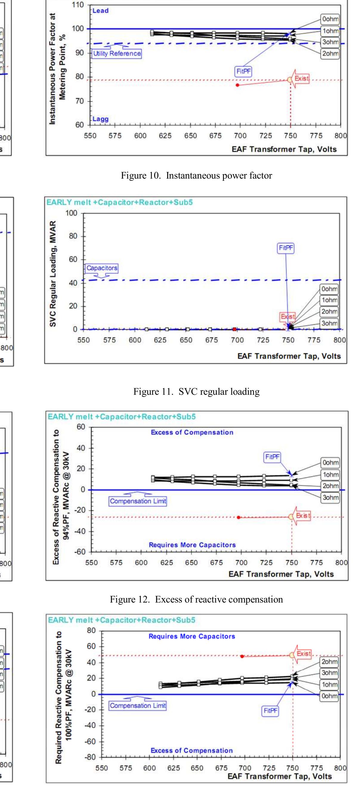
Figure 13. Required reactive compensation
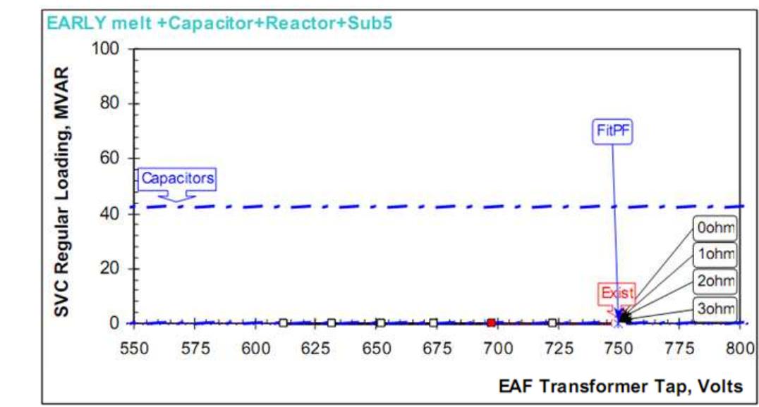
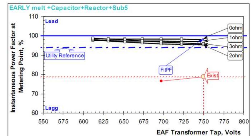
Figure 10. Instantaneous power factor Figure 11. SVC regular loading
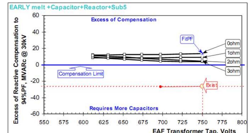
Figure 12. Excess of reactive compensation
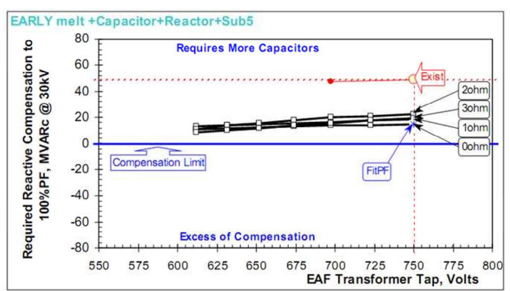
The average capacitor requirements of EAF at 30 kV to fit 94% power factor are: 27.5 MVAR at early melt and 20.2 MVAR at late melt. The LF furnace in worst case requires about 3.5 MVAR. Recommended size is 45 MVAR at 30 kV, providing more than 94% power factor compensation. It is recommended to use the complete 45 MVAR in one filter tuned on the 3 harmonic order (about 2.9, depending upon resonance conditions). Any SVC higher 65-75 MVAR will not provide additional MW to EAF. In case the SVC investment requires, it may be recommended to increase secondary transformer voltage in order to take more advantage of SVC improvements and use a primary reactor. In case of using an SVC it is important to have a voltage regulator control mode as an external loop in addition to the internal and faster flicker loop.
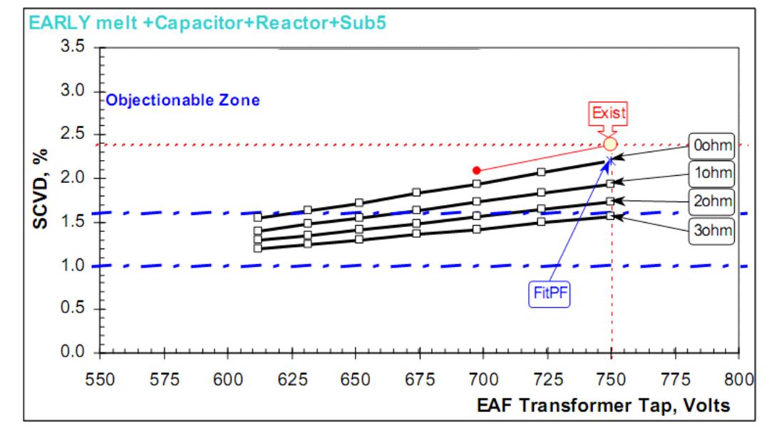
Figure 14. Flicker SCVD
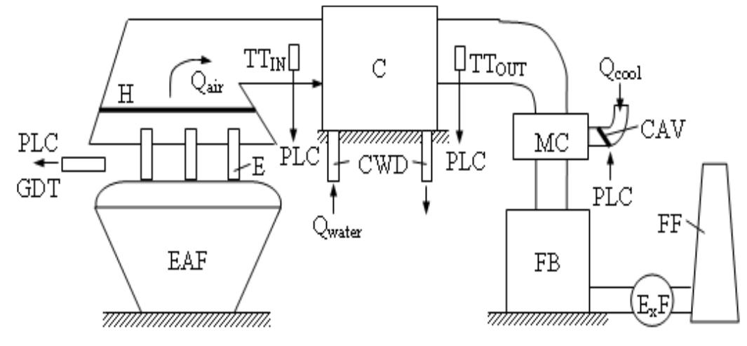
Figure 15. Principle schematic for the undusted filter system. The base drive achieves the fine control of the air flow. When the motor speed reaches the maximum or the lowest level and the process requirements are not satisfied, another motor is connected or removed from operation through the softstarter (SST). When an additional motor fan is energized and when the speed reaches the rated value, the softstarter is by-passed and the motor is connected directly to the grid by means of magneto-thermal protection MTP;. The soft starter is then released until a new motor fan unit needs to be connected or disconnected. In order to avoid the flow jumps when a unit is connected, the frequency converter will decrease the speed of the base drive (when a new unit is connected) or increase it (when a unit is removed) accordingly. All motor fans are programmed to act as a base drive (weekly scheduled operation according to functioning hours).
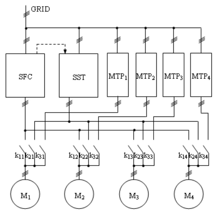
Figure 16. Continuous flow control for cooling with frequency converters and softstater.

Loading Preview
Sorry, preview is currently unavailable. You can download the paper by clicking the button above.
References (19)
- S.I. Deaconu, G.N. Popa and I. Popa, "Energy consumption reduction in dry undust filter equipment for electric arc furnace, "Fifth International Conference in hydrotechnics " vol. 7, ISBN 973-8130-82-4, Sebeş, Romania, 30-31 May 2005, p. 285-288.
- S.I. Deaconu, G.N. Popa and I. Popa, "Modern solutions for the emission reduction in electric arc furnaces" Journal of Automation and Instrumentation no.1/2006, pp.10-12, ISSN 1582-3334
- L. Asiminoaiei, F. Blaabjerg, S. Hansen, P. Thorgersen, "Adaptive Compensation of reactive power with Shunt Active Power Filtres," IEEE Transactions on Industry Applications, vol. 44, no. 3, May/June, 2008, pp.867-877.
- M. Routimo, D.J. Carnavale, "Capacitor Application Issues," IEEE Transactions on Industry Applications, vol. 44, no. 4, pp. 1013-1026, July/August, 2008.
- Th.M. Blooming, A. Mäkinen, M. Salo, R. Seesvuori, J. Kiviranta, H. Tuusa, "Flicker Mitigation with a Hybrid Compensator," IEEE Transactions on Industry Applications, vol. 44, no. 4, pp. 1227-1238, July/August, 2008.
- P. Ashmole and P. Amante, "System flicker disturbances from industrial loads and their compensation," Power Eng. J., vol. 11, no. 5, pp. 213- 218, October, 1997.
- Z. Zhang, N.R. Fahmi and W.T. Norris, "Flicker analysis and methods for electric arc furnace flicker (EAF) mitigation (a survey)," in Proc. IEEE Porto Power Tech. Conf., September 10-13, 2001, vol. 1, 6 pp.
- P. Ashmole, "Quality of supply -voltage fluctuations, Part 2," Power Eng. J., vol. 15, no. 2, pp. 108-114, April, 2001.
- M.M. Morcos and J.C. Gomez, "Flicker sources and mitigation," IEEE Power Eng. Rev., vol.22, no.11, pp.5-10, November 2002.
- IEEE Recommended Practice for Measurement and Limits of Voltage Fluctuations and Associated Light Flicker on AC Power Systems, 2005, Available: IEEE Standard 1453-2004.
- J. Dixon, L, Morán, J. Rodríguez and R. Domke, "Reactive power compensation technologies: State-of-the-art review," Proc. IEEE, vol.93, no.12, December 2005, pp.2144-2164.
- L. Corradini, W. Stefanutti, P. Mattaveli, "Analysis of multisampled current control for active filters," IEEE Transactions on Industry Applications, vol.44, no.6, pp.1785-1794, November/December, 2008.
- F. Nepveux, "Protection of Tuned Capacitor Banks," IEEE Transactions on Industry Applications, vol. 44, no. 4, pp. 973-978, July/August, 2008.
- A.M. Graham, M. Hodder, G. Gates, "Current Methods for Conducting an Arc-Flash Hazard Analysis," IEEE Transactions on Industry Applications, vol. 44, no. 6, pp. 1902-1909, November/December, 2008.
- C. Lascu, L. Asiminoaiei, F. Blaabjerg, I. Boldea, "High performance current controller for selective harmonic compensation in active power filtres, " IEEE Transactions on Power Electronics, vol. 22, no. 5, pp. 1826-1835, September, 2007.
- L. Asiminoaiei, C. Lascu, F. Blaabjerg, I. Boldea, "Performance improvement of shunt active power filter with dual parallel topology, " IEEE Transactions on Power Electronics, vol. 22, no. 1, pp. 247-259, January, 2007.
- M. Aoulkadi, A. Binder, "Comparison of Different Evaluation Methods to Determine Stray Load Losses in Induction Machines," IEEE Transactions on Industry Applications, vol. 44, no. 6, pp. 1675-1682, November/December, 2008.
- C.J. Wu, Y.S. Chuang, C.P. Huang and Y.P. Chang, "Tuning of Static Excitation Systems to Improve Dynamic Performance for Generators Serving Electric Arc Furnaces Loads," IEEE Transactions on Energy Conversion, vol.22, no.2, June 2007, pp.350-357.
- A. Mariscal, AMI GE, Report no. A1360, 2006 (unpublished).